EP0635687B1 - Zwischen Einrohr- und Zweirohrsystem umstellbares Heizkörperanschlussstück - Google Patents
Zwischen Einrohr- und Zweirohrsystem umstellbares Heizkörperanschlussstück Download PDFInfo
- Publication number
- EP0635687B1 EP0635687B1 EP94108841A EP94108841A EP0635687B1 EP 0635687 B1 EP0635687 B1 EP 0635687B1 EP 94108841 A EP94108841 A EP 94108841A EP 94108841 A EP94108841 A EP 94108841A EP 0635687 B1 EP0635687 B1 EP 0635687B1
- Authority
- EP
- European Patent Office
- Prior art keywords
- radiator
- plug
- connection
- return
- pipe system
- Prior art date
- Legal status (The legal status is an assumption and is not a legal conclusion. Google has not performed a legal analysis and makes no representation as to the accuracy of the status listed.)
- Expired - Lifetime
Links
- 238000010438 heat treatment Methods 0.000 claims description 11
- 230000005540 biological transmission Effects 0.000 description 1
Images
Classifications
-
- F—MECHANICAL ENGINEERING; LIGHTING; HEATING; WEAPONS; BLASTING
- F24—HEATING; RANGES; VENTILATING
- F24D—DOMESTIC- OR SPACE-HEATING SYSTEMS, e.g. CENTRAL HEATING SYSTEMS; DOMESTIC HOT-WATER SUPPLY SYSTEMS; ELEMENTS OR COMPONENTS THEREFOR
- F24D19/00—Details
- F24D19/0002—Means for connecting central heating radiators to circulation pipes
-
- F—MECHANICAL ENGINEERING; LIGHTING; HEATING; WEAPONS; BLASTING
- F16—ENGINEERING ELEMENTS AND UNITS; GENERAL MEASURES FOR PRODUCING AND MAINTAINING EFFECTIVE FUNCTIONING OF MACHINES OR INSTALLATIONS; THERMAL INSULATION IN GENERAL
- F16K—VALVES; TAPS; COCKS; ACTUATING-FLOATS; DEVICES FOR VENTING OR AERATING
- F16K11/00—Multiple-way valves, e.g. mixing valves; Pipe fittings incorporating such valves
- F16K11/02—Multiple-way valves, e.g. mixing valves; Pipe fittings incorporating such valves with all movable sealing faces moving as one unit
- F16K11/04—Multiple-way valves, e.g. mixing valves; Pipe fittings incorporating such valves with all movable sealing faces moving as one unit comprising only lift valves
-
- F—MECHANICAL ENGINEERING; LIGHTING; HEATING; WEAPONS; BLASTING
- F24—HEATING; RANGES; VENTILATING
- F24D—DOMESTIC- OR SPACE-HEATING SYSTEMS, e.g. CENTRAL HEATING SYSTEMS; DOMESTIC HOT-WATER SUPPLY SYSTEMS; ELEMENTS OR COMPONENTS THEREFOR
- F24D19/00—Details
- F24D19/0002—Means for connecting central heating radiators to circulation pipes
- F24D19/0014—Connection means adaptable for one and two pipe systems
-
- F—MECHANICAL ENGINEERING; LIGHTING; HEATING; WEAPONS; BLASTING
- F28—HEAT EXCHANGE IN GENERAL
- F28F—DETAILS OF HEAT-EXCHANGE AND HEAT-TRANSFER APPARATUS, OF GENERAL APPLICATION
- F28F9/00—Casings; Header boxes; Auxiliary supports for elements; Auxiliary members within casings
- F28F9/26—Arrangements for connecting different sections of heat-exchange elements, e.g. of radiators
- F28F9/262—Arrangements for connecting different sections of heat-exchange elements, e.g. of radiators for radiators
Definitions
- the invention relates to a switchable between one-pipe and two-pipe system Radiator connector with a flow and a return pipe and two Radiator connection piece, being between the flow and return pipe a bypass line which can be closed by a removable plug is provided.
- each radiator is equipped with a supply line and a return line equipped. The full amount of heat supplied through the supply line flows through the radiator.
- DE-A-31 20 396 describes a radiator connector, in which between the Flow connection and the return connection a closable by means of a plug Bypass line is provided.
- the stopper is designed as a set screw, which by is operated outside.
- the invention has for its object a radiator connector of the beginning mentioned type so that the connector to close the plug the bypass line completely.
- radiator connection piece If the radiator connection piece is used in a two-pipe system the bypass line must be closed with the plug before the final assembly of the two-pipe system.
- the Bypass line used to feed a part of the flow through the supply nozzle Forward the heating medium immediately to neighboring radiators. In this case there is no need to use the plug.
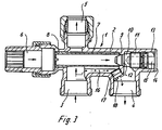
- the radiator connector 1 has a housing 2 and is with a flow connector 3, a return pipe 4 and the radiator connection pipe 5 and 6 equipped.
- a sleeve 7 is provided in the housing and has a threaded piece 8 at one end has and is screwed into an internal thread of the housing, while the other end of the sleeve extends to the seat 9 of a valve body 10, the one Has threaded piece 11 and is screwed into an internal thread of the housing.
- its valve surface 12 lies on the seat surface of the housing and closes off the flow of the heating medium the interior of the sleeve 7 in the return pipe 4.
- the mounting opening 13 arranged in the housing 2 for the as threaded spindle trained valve body 10 can be closed by a cap 14.
- the valve body can be directly or indirectly through the cap 14 be operated.
- the cap 14 can have a pin 15, at least in the area the free end is designed as a polygon and in a polygonal receptacle the threaded spindle can be inserted.
- bypass line between the flow connection 3 and the return connection 4 16 provided, which can be closed by a removable plug 17 is.
- the plug is a screw 17 formed, which in an internally threaded portion of the Bypass line 16 can be screwed.
- the head 18 of the screw 17 is for an operating tool through the Return pipe 4 accessible.
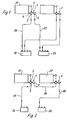
- the connector shown in Fig. 3, in which the bypass line 16 is closed by the screw 17, can in the in Fig. 1st shown two-pipe system can be used.
- the heating medium flows from a flow distributor 19 through the flow line 20 into the flow connection 3, flows around the sleeve 7 and passes through the connection 5 into the heating element 21.
- the heating medium flows through the radiator 21 and then flows through the nozzle 6, the interior of the sleeve 7 and, when the valve is open, through the return nozzle 4 into the return line 22 to the return manifold 23.
- the heating medium flows through the flow distributor 24 the line 25 into the flow connector 3.
- a partial flow then branches off and flows through the bypass line 16 and the nozzle 4 and from there through line 26 to the next radiator 27 while the other Partial flow through the nozzle 5 is supplied to the radiator 21.
- the medium reaches the return manifold 29 via the return line 28.
- radiator connector In the embodiment of the radiator connector according to FIG. 3 form the housing wall provided with the valve seat (9) and the Housing wall with the hole for the plug or screw (17) an obtuse angle.
Landscapes
- Engineering & Computer Science (AREA)
- General Engineering & Computer Science (AREA)
- Mechanical Engineering (AREA)
- Thermal Sciences (AREA)
- Physics & Mathematics (AREA)
- Chemical & Material Sciences (AREA)
- Combustion & Propulsion (AREA)
- Non-Disconnectible Joints And Screw-Threaded Joints (AREA)
- Details Of Heat-Exchange And Heat-Transfer (AREA)
- Branch Pipes, Bends, And The Like (AREA)
- Steam Or Hot-Water Central Heating Systems (AREA)
- Outer Garments And Coats (AREA)
- Aerials With Secondary Devices (AREA)
- Ropes Or Cables (AREA)
- Quick-Acting Or Multi-Walled Pipe Joints (AREA)
Description
- Figur 1
- die Verwendung des Heizkörperanschlußstücks in einem Zweirohrsystem,
- Figur 2
- ein Einrohrsystem, das mit dem erfindungsgemäßen Heizkörperanschlußstück ausgerüstet ist und
- Figur 3
- das Heizkörperanschlußstück im Längsschnitt.
Das Heizmedium durchströmt den Heizkörper 21 und fließt dann durch den Stutzen 6, den Innenraum der Hülse 7 und bei geöffnetem Ventil durch den Rücklaufstutzen 4 in die Rücklaufleitung 22 zum Rücklaufverteiler 23.
Claims (4)
- Zwischen Einrohr- und Zweirohrsystem umstellbares Heizkörperanschlußstück mit einem Vorlauf- (3) und einem Rücklaufstutzen (4) und zwei Heizkörperanschlußstutzen (5,6), wobei zwischen dem Vorlauf- und dem Rücklaufstutzen eine durch einen entfembaren Stopfen verschließbare Bypassleitung (16) vorgesehen ist, dadurch gekennzeichnet, daß der Stopfen ausschließlich durch den Rücklaufstutzen (4) montierbar bzw. demontierbar ist.
- Heizkörperanschlußstück nach Anspruch 1, dadurch gekennzeichnet, daß der Stopfen als in ein mit Innengewinde versehenes Teilstück der Bypassleitung (16) eindrehbare Schraube (17) ausgebildet und der Kopf (18) der Schraube (17) für ein Betätigungswerkzeug durch den Rücklaufstutzen (4) zugänglich ist.
- Heizkörperanschlußstück nach Anspruch 1, dadurch gekennzeichnet, daß der Stopfen als Einsteckbolzen ausgebildet ist.
- Heizkörperanschlußstück nach Anspruch 1, dadurch gekennzeichnet, daß als im Anschlußstück angeordnete, zum Rücklaufstutzen (4) führende Leitung eine Hülse (7) vorgesehen ist, deren eines Ende sich bis zum Sitz (9) eines als Gewindespindel ausgebildeten Ventilkörpers (10) erstreckt, und daß die mit dem Ventilsitz versehene Gehäusewand und die Gehäusewand mit der Aufnahmebohrung des Stopfens einen stumpfen Winkel bilden.
Applications Claiming Priority (2)
| Application Number | Priority Date | Filing Date | Title |
|---|---|---|---|
| DE9310774U DE9310774U1 (de) | 1993-07-19 | 1993-07-19 | Zwischen Einrohr- und Zweirohrsystem umstellbares Heizkörperanschlußstück |
| DE9310774U | 1993-07-19 |
Publications (2)
| Publication Number | Publication Date |
|---|---|
| EP0635687A1 EP0635687A1 (de) | 1995-01-25 |
| EP0635687B1 true EP0635687B1 (de) | 1998-02-04 |
Family
ID=6895766
Family Applications (1)
| Application Number | Title | Priority Date | Filing Date |
|---|---|---|---|
| EP94108841A Expired - Lifetime EP0635687B1 (de) | 1993-07-19 | 1994-06-09 | Zwischen Einrohr- und Zweirohrsystem umstellbares Heizkörperanschlussstück |
Country Status (4)
| Country | Link |
|---|---|
| EP (1) | EP0635687B1 (de) |
| AT (1) | ATE163081T1 (de) |
| DE (2) | DE9310774U1 (de) |
| DK (1) | DK0635687T3 (de) |
Families Citing this family (1)
| Publication number | Priority date | Publication date | Assignee | Title |
|---|---|---|---|---|
| DE102006043801B4 (de) * | 2006-09-13 | 2014-01-23 | Viega Gmbh & Co. Kg | Bauteil zum Kreuzen von mit einem Medium durchströmbaren Rohrleitungen |
Family Cites Families (3)
| Publication number | Priority date | Publication date | Assignee | Title |
|---|---|---|---|---|
| US4129149A (en) * | 1974-10-03 | 1978-12-12 | Aktiebolaget Fellingsbro Verkstader | Control valve means |
| DE3124790A1 (de) * | 1980-07-01 | 1982-05-13 | Polyventions (Suisse) S.A., 8038 Zürich | Rohranschlussvorrichtung, insbesondere fuer zentralheizungssysteme |
| DE3120396A1 (de) * | 1981-05-22 | 1982-12-16 | Stelrad Heizung GmbH, 2857 Langen | "thermostatische ventilgarnitur mit einer umstelleinrichtung zur verwendung in einrohr- und zweirohrheizungsanlagen" |
-
1993
- 1993-07-19 DE DE9310774U patent/DE9310774U1/de not_active Expired - Lifetime
-
1994
- 1994-06-09 DK DK94108841T patent/DK0635687T3/da active
- 1994-06-09 EP EP94108841A patent/EP0635687B1/de not_active Expired - Lifetime
- 1994-06-09 AT AT94108841T patent/ATE163081T1/de not_active IP Right Cessation
- 1994-06-09 DE DE59405207T patent/DE59405207D1/de not_active Expired - Fee Related
Also Published As
| Publication number | Publication date |
|---|---|
| EP0635687A1 (de) | 1995-01-25 |
| DE9310774U1 (de) | 1993-09-02 |
| DK0635687T3 (da) | 1998-09-23 |
| DE59405207D1 (de) | 1998-03-12 |
| ATE163081T1 (de) | 1998-02-15 |
Similar Documents
| Publication | Publication Date | Title |
|---|---|---|
| DE102013111456B4 (de) | Abschaltventil | |
| DE3439585C2 (de) | ||
| DE60211474T2 (de) | Ventil-modul für farbvorrichtung | |
| EP0928939B1 (de) | Röhrenheizkörper mit innerem Rohr | |
| EP1418387A1 (de) | Kompaktheizungsanlage mit zwei Heizkreisen | |
| EP0171004A2 (de) | Ventil zum Regulieren von Teilströmen in zwei oder mehreren Rohrleitungen | |
| EP0635687B1 (de) | Zwischen Einrohr- und Zweirohrsystem umstellbares Heizkörperanschlussstück | |
| DE4431013C1 (de) | Thermostatventil für Plattenheizkörper | |
| EP0107143A1 (de) | Ventil, insbesondere Mischventil | |
| DE3422336C2 (de) | ||
| DE4011111C1 (en) | Panel radiator connection - has feed and return connections joined to connection piece linking two radiator panels and screwed in place | |
| DE4106278C2 (de) | Heizungsventil | |
| DE19744482C1 (de) | Anschlußsystem für Heizkörper | |
| DE2012827C3 (de) | Ventilaufsatz | |
| DE10114992C1 (de) | Heizkörper-Anschlußarmatur und Heizkörper | |
| AT412991B (de) | Verteilerventil | |
| DE3821372A1 (de) | Leitungsanordnung fuer frischwasser | |
| DE3816880C2 (de) | ||
| DE3712625C2 (de) | ||
| DE3735635C2 (de) | ||
| DE3743707A1 (de) | Ventil mit voreinstellung der durchflussmenge | |
| DE3535176A1 (de) | Anschlussarmatur fuer plattenheizkoerper | |
| DE8004466U1 (de) | Vorrichtung zur Wasserverteilung, insbesondere für Heizungsanlagen | |
| DE3435411C2 (de) | Mischventil | |
| DE2412303C3 (de) | Rohrleitungsverteiler für Zentralheizungsanlagen |
Legal Events
| Date | Code | Title | Description |
|---|---|---|---|
| PUAI | Public reference made under article 153(3) epc to a published international application that has entered the european phase |
Free format text: ORIGINAL CODE: 0009012 |
|
| AK | Designated contracting states |
Kind code of ref document: A1 Designated state(s): AT BE CH DE DK FR IT LI NL |
|
| 17P | Request for examination filed |
Effective date: 19950510 |
|
| 17Q | First examination report despatched |
Effective date: 19960809 |
|
| GRAG | Despatch of communication of intention to grant |
Free format text: ORIGINAL CODE: EPIDOS AGRA |
|
| GRAG | Despatch of communication of intention to grant |
Free format text: ORIGINAL CODE: EPIDOS AGRA |
|
| GRAH | Despatch of communication of intention to grant a patent |
Free format text: ORIGINAL CODE: EPIDOS IGRA |
|
| GRAH | Despatch of communication of intention to grant a patent |
Free format text: ORIGINAL CODE: EPIDOS IGRA |
|
| ITF | It: translation for a ep patent filed | ||
| RAP1 | Party data changed (applicant data changed or rights of an application transferred) |
Owner name: FRANZ VIEGENER II GMBH & CO. KG. |
|
| GRAA | (expected) grant |
Free format text: ORIGINAL CODE: 0009210 |
|
| AK | Designated contracting states |
Kind code of ref document: B1 Designated state(s): AT BE CH DE DK FR IT LI NL |
|
| REF | Corresponds to: |
Ref document number: 163081 Country of ref document: AT Date of ref document: 19980215 Kind code of ref document: T |
|
| REG | Reference to a national code |
Ref country code: CH Ref legal event code: NV Representative=s name: ISLER & PEDRAZZINI AG Ref country code: CH Ref legal event code: EP |
|
| REF | Corresponds to: |
Ref document number: 59405207 Country of ref document: DE Date of ref document: 19980312 |
|
| ET | Fr: translation filed | ||
| REG | Reference to a national code |
Ref country code: DK Ref legal event code: T3 |
|
| PLBE | No opposition filed within time limit |
Free format text: ORIGINAL CODE: 0009261 |
|
| STAA | Information on the status of an ep patent application or granted ep patent |
Free format text: STATUS: NO OPPOSITION FILED WITHIN TIME LIMIT |
|
| 26N | No opposition filed | ||
| PGFP | Annual fee paid to national office [announced via postgrant information from national office to epo] |
Ref country code: DE Payment date: 20050603 Year of fee payment: 12 |
|
| PGFP | Annual fee paid to national office [announced via postgrant information from national office to epo] |
Ref country code: AT Payment date: 20050606 Year of fee payment: 12 |
|
| PGFP | Annual fee paid to national office [announced via postgrant information from national office to epo] |
Ref country code: NL Payment date: 20050620 Year of fee payment: 12 |
|
| PGFP | Annual fee paid to national office [announced via postgrant information from national office to epo] |
Ref country code: FR Payment date: 20050621 Year of fee payment: 12 |
|
| PGFP | Annual fee paid to national office [announced via postgrant information from national office to epo] |
Ref country code: BE Payment date: 20050623 Year of fee payment: 12 |
|
| PGFP | Annual fee paid to national office [announced via postgrant information from national office to epo] |
Ref country code: CH Payment date: 20050624 Year of fee payment: 12 |
|
| PGFP | Annual fee paid to national office [announced via postgrant information from national office to epo] |
Ref country code: DK Payment date: 20050627 Year of fee payment: 12 |
|
| PG25 | Lapsed in a contracting state [announced via postgrant information from national office to epo] |
Ref country code: AT Free format text: LAPSE BECAUSE OF NON-PAYMENT OF DUE FEES Effective date: 20060609 |
|
| PG25 | Lapsed in a contracting state [announced via postgrant information from national office to epo] |
Ref country code: LI Free format text: LAPSE BECAUSE OF NON-PAYMENT OF DUE FEES Effective date: 20060630 Ref country code: DK Free format text: LAPSE BECAUSE OF NON-PAYMENT OF DUE FEES Effective date: 20060630 Ref country code: CH Free format text: LAPSE BECAUSE OF NON-PAYMENT OF DUE FEES Effective date: 20060630 Ref country code: BE Free format text: LAPSE BECAUSE OF NON-PAYMENT OF DUE FEES Effective date: 20060630 |
|
| PGFP | Annual fee paid to national office [announced via postgrant information from national office to epo] |
Ref country code: IT Payment date: 20060630 Year of fee payment: 13 |
|
| PG25 | Lapsed in a contracting state [announced via postgrant information from national office to epo] |
Ref country code: NL Free format text: LAPSE BECAUSE OF NON-PAYMENT OF DUE FEES Effective date: 20070101 |
|
| PG25 | Lapsed in a contracting state [announced via postgrant information from national office to epo] |
Ref country code: DE Free format text: LAPSE BECAUSE OF NON-PAYMENT OF DUE FEES Effective date: 20070103 |
|
| REG | Reference to a national code |
Ref country code: DK Ref legal event code: EBP |
|
| REG | Reference to a national code |
Ref country code: CH Ref legal event code: PL |
|
| NLV4 | Nl: lapsed or anulled due to non-payment of the annual fee |
Effective date: 20070101 |
|
| REG | Reference to a national code |
Ref country code: FR Ref legal event code: ST Effective date: 20070228 |
|
| BERE | Be: lapsed |
Owner name: FRANZ *VIEGENER II G.M.B.H. & CO. K.G. Effective date: 20060630 |
|
| PG25 | Lapsed in a contracting state [announced via postgrant information from national office to epo] |
Ref country code: FR Free format text: LAPSE BECAUSE OF NON-PAYMENT OF DUE FEES Effective date: 20060630 |
|
| PG25 | Lapsed in a contracting state [announced via postgrant information from national office to epo] |
Ref country code: IT Free format text: LAPSE BECAUSE OF NON-PAYMENT OF DUE FEES Effective date: 20070609 |