EP0813253A2 - Thermoelektrischer Generator - Google Patents
Thermoelektrischer Generator Download PDFInfo
- Publication number
- EP0813253A2 EP0813253A2 EP97109407A EP97109407A EP0813253A2 EP 0813253 A2 EP0813253 A2 EP 0813253A2 EP 97109407 A EP97109407 A EP 97109407A EP 97109407 A EP97109407 A EP 97109407A EP 0813253 A2 EP0813253 A2 EP 0813253A2
- Authority
- EP
- European Patent Office
- Prior art keywords
- heat
- fuel gas
- thermal input
- fuel
- thermoelectric
- Prior art date
- Legal status (The legal status is an assumption and is not a legal conclusion. Google has not performed a legal analysis and makes no representation as to the accuracy of the status listed.)
- Withdrawn
Links
Images


Classifications
-
- H—ELECTRICITY
- H10—SEMICONDUCTOR DEVICES; ELECTRIC SOLID-STATE DEVICES NOT OTHERWISE PROVIDED FOR
- H10N—ELECTRIC SOLID-STATE DEVICES NOT OTHERWISE PROVIDED FOR
- H10N10/00—Thermoelectric devices comprising a junction of dissimilar materials, i.e. devices exhibiting Seebeck or Peltier effects
- H10N10/10—Thermoelectric devices comprising a junction of dissimilar materials, i.e. devices exhibiting Seebeck or Peltier effects operating with only the Peltier or Seebeck effects
- H10N10/17—Thermoelectric devices comprising a junction of dissimilar materials, i.e. devices exhibiting Seebeck or Peltier effects operating with only the Peltier or Seebeck effects characterised by the structure or configuration of the cell or thermocouple forming the device
-
- H—ELECTRICITY
- H10—SEMICONDUCTOR DEVICES; ELECTRIC SOLID-STATE DEVICES NOT OTHERWISE PROVIDED FOR
- H10N—ELECTRIC SOLID-STATE DEVICES NOT OTHERWISE PROVIDED FOR
- H10N10/00—Thermoelectric devices comprising a junction of dissimilar materials, i.e. devices exhibiting Seebeck or Peltier effects
- H10N10/10—Thermoelectric devices comprising a junction of dissimilar materials, i.e. devices exhibiting Seebeck or Peltier effects operating with only the Peltier or Seebeck effects
- H10N10/13—Thermoelectric devices comprising a junction of dissimilar materials, i.e. devices exhibiting Seebeck or Peltier effects operating with only the Peltier or Seebeck effects characterised by the heat-exchanging means at the junction
Definitions
- the present invention relates to a thermoelectric generator utilizing as heat source the heat of catalytic combustion. Also, the present invention relates to the constitution of a thermoelectric generator usable as an electric source for outdoor application.
- thermoelectric generator As the power source for outdoor use, batteries and engine electric generators have mainly been used. However, in case of a battery, due to the time required for charging, it has been inconvenient for continuous use outdoors.
- the engine generators using gasoline as a fuel has large capacity for generating electricity, but as it shows large sound in operation, it is not suited for example for the power source for speaker or the like, and its use is limited. Accordingly, as the power source for outdoor use which is safe, silent in sound, and adaptable to continuous use with good facility for use, a thermoelectric generator is recommended.
- thermoelectric generator which performs direct conversion of heat to electricity by utilizing the thermoelectric power which is produced when temperature differences are given to thermoelectric material is noted with attention as emergency power source, portable power source, power source for remote place, device for recovering waste heat, etc.
- heat sources for these electric generators there are used heat of combustion, heat of catalyst combustion, heat of exhaust gas, etc., of which the heat utilizing catalytic combustion heat has characteristics such that the temperature adjustment can be easily made by adjustment of flow rate of fuel gas, and combustion heat can be thermally inputted efficiently to the electric generating part by making planar combustion.
- thermoelectric generator utilizing catalytic combustion as heat source an apparatus which was made public in Japanese Patent Publication (Unexamined) No. 85973/19xx.
- thermocouple 23 for thermal discharge, with the high temperature side and the low temperature side of the thermocouple are fixed respectively to the outer wall of the combustion chamber 22 and the fan 24 for heat discharge.
- thermoelectric conversion efficiency of the generator utilizing the catalytic combustion as illustrated as heat source is generally low at 4%. Accordingly, if the performance of the thermoelectric element is unchanged, in order to improve efficiency, there is required a constitution to utilize the catalytic combustion more efficiently. Namely, there is required a constitution to reduce the rate of the heat discharged without being utilized for thermoelectric conversion out of the formed catalytic combustion heat.
- the generator of the constitution as in FIG. 10 because the exhaust gas of high temperature at about 250 - 600°C is discharged from the combustion chamber, the generator involves problems of safety and convenience of use, especially in case of the generator for civil use.
- An object of the first invention is to provide, in consideration of such task of the conventional thermoelectric generator, a thermoelectric generator using catalytic combustion heat as heat source, with which efficient thermal input of catalytic combustion heat is made possible and the temperature of the exhaust gas is reduced.
- an object of the second invention is to provide a thermoelectric generator using catalytic combustion heat as heat source, with which efficient thermal input of catalytic combustion heat is made possible, and to provide compact and practical constitution of the thermoelectric generator.
- an object of the third invention is to provide a thermoelectric generator having compact and high performance air cooling type heat discharge system.
- thermoelectric generator of the present invention using catalytic combustion heat of fuel gas as a heat source has a construction wherein a thermoelectric element or a planar electric generation unit comprising thermoelectric elements has a construction held between the thermal input part and the heat radiation part, having fuel gas supply means and means for mixing fuel gas with air, and having a structure that the combustion heat can be directly supplied to the thermoelectric element by burning the mixed gas of fuel with air in a catalyst part arranged in said thermal input part, said thermal input part having a heat conductive end plate and a catalyst part which are in contact with the thermoelectric element, the face opposite to said thermoelectric element of said heat conductive end plate having a structure of convex and concave configuration, and said catalyst part being constituted in said convex and concave configuration surface.
- thermoelectric generator of the present invention using catalytic combustion heat of fuel gas as a heat source is provided with a pair of thermoelectric elements or planar electric generation units comprising thermoelectric elements held between a thermal input part and a heat radiation part, in a structure to share said thermal input part, having fuel gas supply means, and means for mixing a fuel gas with air, and having a structure of being capable of directly supplying the combustion heat to said thermoelectric element by burning the mixed gas of fuel with air in a catalyst part arranged in said thermal input part, characterized in that said thermal input part comprises a heat conductive end plate and a catalyst part, a surface opposite to said thermoelectric element of said heat conductive end plate has convex and concave shaped structure, and said catalyst part is constituted on said convex and concave shaped surface.
- thermoelectric generator of the present invention using catalytic combustion heat of fuel gas as a heat source has a construction wherein a thermoelectric element or a planar electric generation unit comprising thermoelectric elements has a construction held between the thermal input part and the heat radiation part, having fuel gas supply means and means for mixing fuel gas with air, and having a structure that the combustion heat can be directly supplied to the thermoelectric element by burning the mixed gas of fuel with air in a catalyst part arranged in said thermal input part, characterized by having means for thermal recovery and simultaneously reducing the temperature of exhaust gas by making heat exchange between the exhaust gas from the thermal input part and the fuel before being supplied to said thermal input part.
- thermoelectric generator of the present invention using catalytic combustion heat of fuel gas as a heat source has a construction wherein a thermoelectric element or a planar electric generation unit comprising thermoelectric elements has a construction held between the thermal input part and the heat radiation part, having fuel gas supply means and means for mixing fuel gas with air, and having a structure that the combustion heat can be directly supplied to the thermoelectric element by burning the mixed gas of fuel with air in a catalyst part arranged in said thermal input part, said means for mixing fuel gas with air being constituted by a nozzle for jetting a fuel gas and a throat part for sending the jetted fuel gas and the air mixed in the form of being involved in the fuel gas into the thermal input part, and being provided with means for carrying out thermal recovery by heat exchange between the exhaust gas from said thermal input part and the mixed gas passing in the throat part, and for reducing the temperature of the exhaust gas.
- thermoelectric generator of the present invention using catalytic combustion heat of fuel gas as a heat source has a construction wherein a thermoelectric element or a planar electric generation unit comprising thermoelectric elements has a construction held between the thermal input part and the heat radiation part, having fuel gas supply means and means for mixing fuel gas with air, and having a structure that the combustion heat can be directly supplied to the thermoelectric element by burning the mixed gas of fuel with air in a catalyst part arranged in said thermal input part, said means for mixing fuel gas with air being constituted by a nozzle for jetting a fuel gas and a throat part for sending the jetted fuel gas and the air mixed in the form of being involved in the fuel gas into the thermal input part, characterized in that the air to be mixed in the form of being involved in a fuel gas is the air which is heat exchanged by the exhaust gas from said thermal input part.
- thermoelectric generator of the present invention comprises a thermal input part using the catalytic combustion heat of fuel gas as a heat source, a heat radiation part having a heat conductive container whose at least a part of the outer surface is of a fin shape, more than a pair of planar electric generation units held between the outer wall of said thermal input part and the inner wall of said heat radiation part, utilizing a thermoelectric element, fuel gas supply means including a fuel tank, and mixing means for mixing a fuel gas with air, said fuel gas supply means and said mixing means being installed in a heat conductive container in said heat radiation part, characterized by directly supplying the combustion heat to the thermoelectric element of said thermoelectric generation unit by burning the mixed gas of fuel with air in a catalyst part disposed in said thermal input part, and at the same time air cooling or water cooling said heat radiation part.
- thermoelectric generator of the present invention comprises a thermal input part using the catalytic combustion heat of fuel gas as a heat source, a heat radiation part having a heat conductive container whose at least a part of the outer surface is of a fin shape, more than a pair of planar electric generation units held between the outer wall of said thermal input part and the inner wall of said heat radiation part, utilizing a thermoelectric element, a fuel tank, a fuel gas transporting means, and mixing means for mixing a fuel gas with air, said mixing means being installed in a heat conductive container in said heat radiation part, said fuel tank being freely installed in or out of the container, and connected to said mixing means through said fuel gas transporting means, characterized by directly supplying the combustion heat to the thermoelectric element by burning the mixed gas of fuel with air in a catalyst part disposed in said thermal input part, and air cooling or water cooling said heat radiation part.
- thermoelectric generator of the present invention comprises a thermal input part using the catalytic combustion heat of fuel gas as a heat source, a heat radiation part constituted by a heat conductive plate whose at least a part of the outer surface is of a fin shape, a cooling water container provided outside said heat radiation pat, more than a pair of planar electric generation units held between the outer wall of said thermal input part and the inner wall of said heat radiation part, utilizing a thermal element, fuel gas supply means including a fuel tank , and mixing means for mixing a fuel gas with air, said fuel gas supply means and said mixing means being installed in a heat conductive container in said heat radiation part, characterized by directly supplying the combustion heat to said thermoelectric element of said thermoelectric generation unit by burning the mixed gas of fuel with air in a catalyst part disposed in said thermal input part, and water cooling said heat radiation part by supplying water to said cooling water container.
- thermoelectric generator of the present invention comprises a thermal input part for inputting heat, a heat radiation part having a fin part and a fan, an electric generation unit held between said heat radiation part and said thermal input part for carrying out thermoelectric conversion by utilizing a thermoelectric element, and fuel supply means for supplying fuel, being designed to supply heat directly to the high temperature side of said thermoelectric element, simultaneously air cool the radiation part which is in contact with the radiation side of said thermoelectric element and carry out thermoelectric generation, characterized in that the whole or a part of said fan is stored in the fin part of said radiation part.
- FIG. 1 is a sectional view showing the constitution of the thermoelectric generator according to Embodiment 1, wherein the upper drawing is a cross-sectional view, and the lower drawing is a vertical sectional view.
- the part 1 is a thermoelectric element or planar electric generating unit made by connecting in series a plurality of thermoelectric elements, being held between the radiating part 2 and the thermal input part 3.
- the radiation part 2 is constituted by an aluminum fin 4 for radiation and a fan 5.
- the heat input part 3 comprises a heat conductive end plate 6 and a catalytic part 7.
- the heat conductive end plate 6 has a configuration of comb shaped heat exchange fin so that the face opposite to the joining face with the thermoelectric element 1 has increased surface area.
- the catalyst part 7 is installed in a manner to cover the surface of the heat conductive end plate 6 on the side of the comb shaped heat exchange fin side.
- the part 8 is a side wall, and 9 is a heat insulating material such as alumina wool.
- the part 10 is a fuel tank for holding the fuel such as butane, being connected to the thermal input part 3 through the nozzle 11 and the throat part 12 which are the mixing means of fuel gas with air.
- the part 13 is a gas flow inlet
- 14 is an exhaust port.
- thermoelectric generator With respect to the thermoelectric generator constituted as above, the operation thereof is explained below.
- the fuel jetted from the nozzle 11 becomes a mixed gas involving the surrounding air, and passes through the throat part 12 to be sent into the thermal input part 3 from the gas flow inlet.
- the charged mixed gas shows catalytic combustion on the catalyst part 7 in the thermal input part 3, after which it is discharged outside the generator from the exhaust port 14.
- the catalytic combustion heat obtained in the thermal input part 3 reaches the high temperature side surface of the thermoelectric element 1 through the heat conductive end plate 6.
- thermoelectric power As the low temperature side of the thermoelectric element 1 is in contact with the radiation part 2, there occurs temperature difference between the high temperature side and the low temperature side of thermoelectric element 1 and electric generation is performed by thermoelectric power.
- thermoelectric element by using a heat conductive end plate of comb shaped structure, a thermal input part of a type integral with the heat exchanger can be constituted, and accordingly, the catalytic combustion heat can be efficiently inputted to the high temperature side surface of the thermoelectric element. Also, as the heat conductive end plate and the catalyst part are in mutual contact, excessive rise of the surface temperature of the combustion part can be prevented to make it possible to realize a constitution suited for the heat resistance of the thermoelectric element.
- the thermal input part is formed into such constitution as to surround the catalyst part which is formed on the surface side of the comb shaped fin input of each heat conductive end plate, the surface areas of the catalyst part and the fin can be doubled without changing the volume of the thermal input part. Therefore, it is possible to constitute a thermal input part of higher density. Concrete example of it is shown in the next passage.
- thermoelectric generator wherein a thermoelectric element or a pair of planar electric generator units comprising thermoelectric elements are bonded to both sides of the thermal input part, and snapped between the thermal input part and the radiation part.
- the construction of the heat conductive end plate 6 of the thermal input part 3 is the same as that of Embodiment 1, but in the style of the present embodiment a pair of heat conductive end plates 6 are combined in a manner that the comb shaped fin side surfaces of a pair of heat conductive end plates 6 are opposed, and the catalyst part 7 is formed on said comb shaped fin.
- a planar electric generation unit 1 comprising a thermoelectric element.
- a planar electric generation unit 1 there is used one having a construction wherein a plurality of thermoelectric elements arranged on a plane are connected in series.
- the construction of the radiation part 2 is similar to that of Embodiment 1, wherein the radiation part 2 is installed in a manner to hold these planar generating units 1 with the thermal input part 3. Since the operation of the generator of this constitution is the same as that of Embodiment 1, description thereof is omitted.
- the combustion chamber which is a thermal input part 3 into such construction as to have the heat conductive end plates positioned in opposite manner, the surface area of the heat exchange fins can be increased simultaneously with the increase in the catalytic combustion area, with the volume of the combustion chamber left unchanged.
- a higher density heat source can be formed.
- combustion heat discharged outside the generator from the surface of the thermal input part can be largely decreased, thereby permitting the thermal input in good efficiency. As a result, it becomes possible to constitute a compact thermoelectric generator with greatly improved generation efficiency.
- FIG. 3 is a block diagram of a thermoelectric generator in the case of using a metal carried catalyst 15 as a catalyst part.
- the catalyst part 15 has a construction wherein ceramic fine powder 17 such as alumina carrying a precious metal catalyst of platinum or the like is applied to the surface of a heat-resistant metal thin plate 16 having a thickness of no more than 0.5 mm.
- a heat-resistant metal thin plate 16 having a thickness of no more than 0.5 mm.
- the material having good processing property such as SUS plate may be used.
- Other constitution and operation are the same as those of Embodiment 1.
- a high performance catalyst part can be produced at a low cost. Furthermore, in case of the degradation the catalyst part can be simply replaced to improve practical utility.
- FIG. 4 An example where a metal carrier catalyst having a rectangular wave shape at the end of the gas flow inlet side is used as a metal carrier catalyst 15 is shown in FIG. 4.
- the right side figure is a cross-sectional view
- the left side figure is a vertical section taken from the right side thereof.
- a gas flows in from the right side of the left figure (the right side here practically corresponds to the lower part).
- a metal carrier catalyst 15 is formed on a part of the fin side surface of the heat conductive end plate 6. That is to say, in the left side figure, on the base plate part 6a of the end plate 6, there are provided in projection 8 fins 6b of the end plate 6 in lateral direction.
- the catalyst is formed only to about 2/3 part to the left
- the catalyst 15 is wholly formed
- the catalyst 15 is formed only to about 2/3 part to the left.
- the succeeding fin parts 6b are of the similar state.
- the end plate base plate 6a between those fins 6b there exist alternately the portions covered wholly with the catalyst 15 and the portions covered only to about 2/3 to the left part.
- the catalyst part 15 on the gas inlet side becomes less, the catalyst combustion on the inflow side which tends to become high temperature can be dispersed, so that the heat can be conducted without unevenness to the high temperature side surface of the thermoelectric element through the heat conductive end plate. Accordingly, the difference of thermoelectric powers between the thermoelectric material chips constituting the thermoelectric elements can be dissolved, and the damage or deterioration of the elements caused by the local excess of the heat resistant temperature of the element can be prevented, with the result that the efficiency and durability of the generator can be improved.
- the shapes of the catalyst part end there may be corrugated, V-shaped, etc. besides the rectangular shape as illustrated in the left view of FIG. 4.
- FIG. 5 is a sectional view of a thermoelectric generator in the case where the thickness of the heat conductive end plate 6 is changed so as to become larger in the vicinity of the gas flow inlet 13 and smaller in the vicinity of the exhaust port 14.
- the upper view is a cross-section, and the lower view is a vertical section.
- thermoelectric powers between the thermoelectric material chips constituting the thermoelectric element can be dissolved, leading to the improvement of the electric generation efficiency of the element. Also, it is possible to prevent damage or deterioration of the element caused by local excess of the heat resistant temperature of the element, and the durability of the generator can be improved.
- the catalyst part 15 when the catalyst part 15 is reduced to half area, namely, when the catalyst part on the inflow side 15 is made not to cover either the base part 6a of the end plate 6 or the fin part 6b, the position on which the catalytic combustion occurs in concentration comes to nearly the central part of the joint face with the thermoelectric element or planar electric generation unit.
- the thickness of the base plate 6a of the heat conductive end plate 6 may be so set as to become the largest in the neighborhood of the position of catalytic combustion near the center and smaller toward both ends of the end plate 6.
- FIG. 6 is a sectional view showing the constitution of the thermoelectric generator according to Embodiment 4.
- the construction wherein a planar electric generating unit 1 made by connecting in series a thermoelectric element or a plurality of thermoelectric elements is held between the heat radiation part 2 and the heat input part 3 is the same as in Embodiment 1.
- the side wall 8 of the thermal input part 3 of this constitution use of material having good heat conductivity such as aluminum is preferable.
- thermoelectric generator With respect to the thermoelectric generator constituted as above, the operation thereof is described.
- the fuel jetted from the nozzle 11 becomes a mixed gas involving the circumferential air, passes through the throat part 12, and is sent into the thermal input part 3.
- the heat obtained on catalytic combustion of the mixed gas sent in on the catalyst 7 in the thermal input part 3 is utilized for electric generation by the thermoelectric element 1 in the same manner as in Embodiment 1.
- the exhaust gas produced on catalytic combustion passes through the exhaust gas flow path 18 from the exhaust port 14, and, coming into contact with the outer surface of the side wall 8 of the thermal input part 3 in the exhaust gas flow path 18, a fuel gas tank 10, an evaporation chamber 20, a flow path 19, and a throat pat 12, and is discharged outside the generator while carrying out heat exchange.
- thermoelectric generator by making heat exchange between the exhaust gas from the thermal input part 3 and the fuel gas in the tank 10, flow path 18, evaporation chamber 20, and throat part 12, a part of the discharged catalyst combustion heat can be recovered to bring the mixed gas before combustion to high temperature. Because of this, the calorific power to the amount of gas used increases and the efficiency of thermoelectric generator can be improved. Moreover, the temperature of the high temperature exhaust gas at about 250 - 600°C can be reduced, and practical thermoelectric generator extensively applicable to civil use can be constituted.
- thermoelectric generator constituted to make heat exchange between the exhaust gas from the thermal input part 3 and the liquid fuel in the fuel tank 10.
- the electric generator of FIG. 7 has a structure of a pair of generating units 1 holding a thermal input part 3 to be arranged in opposed state, in which an exhaust gas flow path 18 is set in a manner to surround the fuel tank 10.
- the fuel warmed in the fuel tank 10 is further warmed by the heat discharged from the side surface of the thermal input part 3 in the flow path 19 set to run along the side surface of the thermal input part 3 and evaporated, and sent to the nozzle 11.
- thermoelectric generator In the constitution as in FIG. 7, by the heat exchange between the liquid fuel in the fuel tank 10 and the exhaust gas from the thermal input part 3, evaporation of fuel is accelerated to make it possible to constitute more efficient, practical, and compact thermoelectric generator.
- thermoelectric generator constituted to make heat exchange between the exhaust gas from the thermal input part 3 and the fuel gas and air mixed gas which pass through the throat part 12.
- the generator of FIG. 8 has a structure made by holding the thermal input part 3 with a pair of generating units 1 in opposed state, wherein the exhaust gas flow path 18 is set so that the exhaust gas from the thermal input part 3 passes through the space between the heat conductive end plate 6 on both faces of the thermal input part 3 and the generating unit 1, comes into contact with the surface of the slot part 12, and then is discharged outside from the generator.
- a compact generator furnished with the means for efficiently recovering the exhaust heat and simultaneously reducing the exhaust gas temperature by making heat exchange between the exhaust gas and the heat conductive end plate 6 and mixed gas before combustion.
- FIG. 9 shows a thermoelectric generator constituted to make heat exchange between the exhaust gas from the thermal input part 3 and the air before being mixed with the fuel gas as the means for cooling the exhaust gas simultaneously with thermal recovery.
- the electric generator of FIG. 9 has a structure made by holding the thermal input part 3 with a pair of generating units 1 in opposed state, wherein the exhaust gas flow path 18 is set so that the exhaust gas from the thermal input part 4 passes through the space between the heat conductive end plate 6 on both faces of the thermal input part 4 and the generating unit 1, and then is discharged outside from the generator.
- a part of the exhaust gas flow path 18 has such construction that fins are formed on both sides or one side so as to make heat exchange between the high temperature exhaust gas in the flow path and the air in the surrounding of the flow path.
- the air which has been heat exchanged here is mixed with the fuel gas jetted from the nozzle 11 and sent into the throat part 12.
- a compact generator provided with such means that, by carrying out heat exchange between the exhaust gas and the heat conductive end plate 6 and pre-combustion air, the exhaust heat can be efficiently recovered, and the exhaust gas temperature can be lowered.
- thermoelectric generator As described above, according to the first invention, there can be provided a constitution of a compact, highly efficient thermoelectric generator with which the thermal input can be made in higher density in a thermoelectric generator having the catalytic combustion heat as heat source.
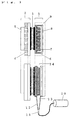
- FIG. 11 is a sectional view showing the constitution of the thermoelectric generator according to Embodiment 1.
- FIG. 12 is an enlarged view of the thermal input part 33 thereof.
- the part 31 is a pair of thermoelectric elements or a planar electric generating unit made by connecting in series a plurality of thermoelectric elements, being pinched between the radiating part 32 and the thermal input part 33 and set on both sides of the thermal input part 33.
- the radiating part 32 is constituted by an aluminum rectangular parallelepiped type container having fin shape on the outside of the four sides.
- the heat input part 33 is formed, as shown in FIG.
- the heat conductive end plate 34 preferably is made of aluminum die cast which has good processing property.
- the catalyst part 35 is installed in a manner to cover the surface of a comb shaped heat exchange fin of heat conductive end plate 34.
- the catalyst part 35 is installed in a manner to cover the surface of the heat conductive end plate 34 on the side of the comb shaped heat exchange fin side.
- a heat resistant metal thin plate having a thickness of no more than 0.5 mm made by applying ceramic fine powder such as alumina carrying a precious metal catalyst such as platinum thereto.
- the part 7 is a fuel tank, for which the commercialized butane gas cylinder for cassette burner is used straightly.
- the fuel tank 37 is connected to the thermal input part 33 through the nozzle 38 and the throat part 39 which are the mixing means of fuel gas with air.
- the thermal input part 33 being provided with an exhaust gas pipe 36, is led to a part outside the container from the top face of the radiation vessel.
- thermoelectric generator With respect to the thermoelectric generator constituted as above, the operation thereof is explained below.
- the fuel jetted from the nozzle 38 becomes a mixed gas involving the air from the upper face of the radiation part, and passes through the throat part 39 to be sent into the thermal input part 33 from the gas flow inlet.
- the charged mixed gas shows catalytic combustion on the catalyst part 35 in the thermal input part 33, after which it is discharged outside the generator by the exhaust gas pipe 36.
- the catalytic combustion heat obtained in the thermal input part 33 reaches the high temperature side surface of the thermoelectric element 31 through the heat conductive end plate 34.
- the larger electromotive force can be obtained by cooling with water rather than by cooling with air.
- the upper face of the generator may be exposed to air and the generator dipped in water.
- thermoelectric element by using a heat conductive end plate of comb shaped structure, a thermal input part of a type integral with the heat exchanger can be constituted, and accordingly, the catalytic combustion heat can be efficiently inputted to the high temperature side surface of the thermoelectric element. Also, as the heat conductive end plate and the catalyst part are in mutual contact, excessive rise of the surface temperature of the combustion part can be prevented to make it possible to realize a constitution suited for the heat resistance of the thermoelectric element.
- the fuel supply part can be kept at high temperature, and it becomes possible to send the fuel gas of high temperature and high pressure into the combustion chamber, and combustion in good efficiency can be realized.
- the respective parts such as thermal input part, gas tank, and generating unit, are all contained in the radiation part vessel, the whole generator can be dipped in water, so that a low priced, highly efficient water cooling system can be realized. In case of the water cooling system, it becomes unnecessary to supply power for driving radiation fan so as to arouse forced convection, and the electric power obtained by thermoelectric conversion can be wholly taken out externally.
- the fuel tank is set at the top part of the thermal input part, but the same may be set at the lower part of the thermal input part.
- the exhaust gas is formed from the upper part, the exhaust gas pipe can be short, and piping is easy.
- FIG. 11 is an embodiment of a case where a pair of generating units are used, when constitution is made to arrange two pairs of generating units on four faces of the thermal input part, it is needless to say that a generator of higher output can be provided.
- a fuel tank may be constituted by a heat resistant vessel and a structure to infuse a fuel gas may be adopted.
- FIG. 13 is a sectional view showing the constitution of the thermoelectric generator according to Embodiment 2.
- the part 7 is a fuel tank, for which a commercialized butane gas cylinder for cassette burner is directly used.
- the fuel tank 37 is connected to the nozzle 38 and the throat part 39 which are the mixing means of fuel gas with air, through a gas tube 41.
- the fuel tank can be freely set in and outside the container, within the length of the gas tube 41.
- Other constitution is the same as in Embodiment 1.
- thermoelectric generator as constituted above is the same as in Embodiment 1.
- thermoelectric element by using a heat conductive end plate of comb shaped structure, a thermal input part of a type integral with the heat exchanger can be constituted, and accordingly, the catalytic combustion heat can be efficiently inputted to the high temperature side surface of the thermoelectric element. Also, as the heat conductive end plate and the catalyst part are in mutual contact, excessive rise of the surface temperature of the combustion part can be prevented to make it possible to realize a constitution suited for the heat resistance of the thermoelectric element.
- the fuel tank does not show temperature rise, and when it is adapted to the use such as AV power source, convenience and safety in fuel supply can be secured.
- the gas sent to the combustion part can be preheated, and efficient combustion can be realized.
- the whole electric generator can be dipped in water, and cheap and highly efficient water cooling system can be realized.
- the water cooling system it becomes unnecessary to supply power for driving radiation fan so as to arouse forced convection, and the electric power obtained by thermoelectric conversion can be wholly taken out externally.
- the fuel tank may be constituted by a heat resistant container, so as to permit infusion of fuel gas.
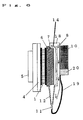
- Embodiment 3 is shown. There is shown a constitution of a thermoelectric generator having a construction wherein a thermoelectric element or a pair of planar electric generation units 31 comprising thermoelectric elements are joined to both sides of the thermal input part 33, and held by a pair of heat radiation part 32 comprising heat conductive plates.
- the outer surface of the heat conductive plate of the radiator 32 has a fin shape so as to increase of the heat exchange area.
- On the outer surface of this radiator there is installed a pair of removable cooling water tank 40, thereby making it possible to carry out either air cooling or water cooling.
- the nozzle part 8 and the fuel tank 9 are connected by a tube 41.
- Other structures are same as in Embodiment 1.
- thermoelectric element by using a heat conductive end plate of comb shaped structure, a thermal input part of a type integral with the heat exchanger can be constituted, and accordingly, the catalytic combustion heat can be efficiently inputted to the high temperature side surface of the thermoelectric element. Also, as the heat conductive end plate and the catalyst part are in mutual contact, excessive rise of the surface temperature of the combustion part can be prevented to make it possible to realize a constitution suited for the heat resistance of the thermoelectric element.
- the fuel tank does not show temperature rise, and when it is adapted to the use such as AV power source which requires continuous supply of fuel, convenience and safety in fuel supply can be secured. Also, in FIG. 14, because the nozzle part or a mixing part of fuel gas with air is warmed by exhaust heat from the thermal input part, highly efficient combustion can be carried out. Efficient combustion can be realized.
- thermoelectric generator for outdoor use.
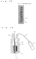
- FIG. 15(a) is a vertical sectional view of the thermoelectric generator of Embodiment 1 of the third invention
- FIG. 15(b) is a front view of the radiation part 60 of said thermoelectric generator.
- the part 51 is a planar electric generation unit made by connecting a pair of thermoelectric elements or a plurality of thermoelectric elements in series. It is held between the fin part 52 and the thermal input part 53, and installed on both sides of the thermal input part 53.
- the fin part 52 is an aluminum single plate having a large number of fins 52c on the outer surface of the disc shaped base plate. As shown in FIG.
- the fin 52c is positioned low or does not exist, where a DC axial flow fan 54 is installed.
- the fin 52c is radially formed so that the compulsory air of the fan 54 flows radially from the center of the fan 54.
- the part 52b is a gap between them.
- the thermal input part 53 comprises a heat conductive combustion chamber 55 of aluminum material and a combustion part 56 installed inside the combustion chamber 55. It is desirable for the combustion chamber 55 to have a fin structure on the inner wall.
- the part 57 is a fuel tank, and is connected to the combustion chamber 55 through the nozzle 58 and the throat part 59.
- thermoelectric generator constituted as above, the operation thereof is explained as follows.
- a commercialized butane gas is used as a fuel.
- the fuel gas jetted from the nozzle 58 becomes a mixed gas involving air, it is passed through the throat part 59, and burns in the combustion chamber 55.
- the produced exhaust gas is discharged outside the generator from the exhaust port on the upper part of the combustion chamber 55.
- the combustion heat obtained in the thermal input part 53 is supplied to the high temperature side surface of the thermoelectric element of the planar electric generation unit 51, and as the low temperature side of the thermoelectric element is in contact with the fin part 52, a temperature difference is formed between the high temperature side and the low temperature side of the thermoelectric element, and electric generation by thermoelectric power takes place.
- the generation output reaches a size necessary for driving the fan 54, the fan 54 starts to rotate, the temperature difference formed on the thermoelectric element and the accompanied thermoelectric power increase, and in the meantime the power reaches the normal state.
- the electric generator of this embodiment When the electric generator of this embodiment is driven, it requires about 30 seconds until the two fans (DC 12V, 100 mA) come to start, and about 5 - 8 minutes until the output (15W) stabilizes.
- the surface temperature of the element at the time of the stabilization of output was 210°C on the high temperature side and 90°C on the low temperature side.
- the volume of the radiation part 60 can be drastically constrained. Also, due to the constitution of leading the forced air radially from the central part of the fan 54 in the gap of the fin 52c, resistance by the fin 52 is decreased, and the air volume of fan can be increased. As a result, it has become possible to utilize the fan capacity to the maximum extent, leading to the improvement of performance of the radiation part 60. Simultaneously, the outlet temperature of the heat exchanged air can be suppressed to a low temperature, and safety can be secured.
- FIG. 15 there is adopted a constitution wherein a gas tank is installed at the bottom part of the generator, and the fuel gas is preheated with the heat from the fin part.
- the tank may be externally set. In such a case, it is desirable to make such constitution that the fuel gas can be preheated with the combustion heat or exhaust air heat before it is sent into the nozzle.
- planar uniform thermal input can be made, so that a generator having higher efficiency can be constituted.
- a generator as means for recovering a part of the waste heat by utilizing the waste heat of fuel battery or engine.
- FIG. 16(a) is a vertical sectional side view showing the constitution of the heat radiation part 60 of the thermoelectric generator according to Embodiment 2 of the third invention
- FIG. 16(b) is a front view of the heat radiation part 60 of he thermoelectric generator thereof.
- the part 62 is an aluminum fin part
- 54 is a DC axial flow fan.
- the part 61 is a motor part of the fan.
- the motor part 61 is buried in the fin 52 through the heat insulation layer 62.
- a ceramic material such as alumina wool can be used for the heat insulation layer 62.
- a heat insulation layer may be provided by an air layer of about several millimeters.
- thermoelectric generator having the above constitution of the heat radiation part is the same as that of Embodiment 1, excepting the following points.
- the motor part can be kept to 70°C or lower, so that the durability of the fan 54 can be improved.
- the present invention can be applied by making the thicknesses of the peripheral part and central part of the fin bottom plate or the thickness of the heat insulation layer optimum.
- thermoelectric generator utilizing as a heat source combustion heat or waste heat including catalytic combustion heat, it becomes possible to make compact constitution of highly efficient and durable heat radiation part, and accordingly it is possible to realize reduction in size and weight or elevation of performance of a thermoelectric generator.
Applications Claiming Priority (2)
| Application Number | Priority Date | Filing Date | Title |
|---|---|---|---|
| JP149239/96 | 1996-06-11 | ||
| JP8149239A JPH09329058A (ja) | 1996-06-11 | 1996-06-11 | 熱電発電器 |
Publications (2)
| Publication Number | Publication Date |
|---|---|
| EP0813253A2 true EP0813253A2 (de) | 1997-12-17 |
| EP0813253A3 EP0813253A3 (de) | 2006-01-25 |
Family
ID=15470931
Family Applications (1)
| Application Number | Title | Priority Date | Filing Date |
|---|---|---|---|
| EP97109407A Withdrawn EP0813253A3 (de) | 1996-06-11 | 1997-06-10 | Thermoelektrischer Generator |
Country Status (3)
| Country | Link |
|---|---|
| US (1) | US5917144A (de) |
| EP (1) | EP0813253A3 (de) |
| JP (1) | JPH09329058A (de) |
Cited By (3)
| Publication number | Priority date | Publication date | Assignee | Title |
|---|---|---|---|---|
| DE102007063173A1 (de) * | 2007-12-19 | 2009-06-25 | Bayerische Motoren Werke Aktiengesellschaft | Thermoelektrischer Generator |
| WO2014087341A3 (en) * | 2012-12-04 | 2014-10-16 | Van Lingen Paul Sidney Alexander | Thermoelectric generator arrangement |
| EP2232694A4 (de) * | 2007-12-18 | 2015-12-02 | Cataflow Technologies Inc | Wärmeverfolgungsvorrichtungen mit einem thermoelektrischen generator |
Families Citing this family (28)
| Publication number | Priority date | Publication date | Assignee | Title |
|---|---|---|---|---|
| US6410842B1 (en) | 2000-05-19 | 2002-06-25 | Teledyne Energy Systems A Division Of Teledyne Brown Engineering, Inc. | Automatic burner driven generator system |
| JP2002153034A (ja) * | 2000-11-07 | 2002-05-24 | Sanshin Ind Co Ltd | 船外機における発電装置 |
| US6497571B1 (en) | 2001-04-20 | 2002-12-24 | Teledyne Energy Systems, A Division Of Teledyne | Durable catalytic burner system |
| US7313916B2 (en) | 2002-03-22 | 2008-01-01 | Philip Morris Usa Inc. | Method and apparatus for generating power by combustion of vaporized fuel |
| JP4495419B2 (ja) * | 2002-11-11 | 2010-07-07 | パナソニック電工株式会社 | 燃焼装置および熱電発電装置 |
| AU2003294155A1 (en) * | 2002-12-26 | 2004-07-22 | Toyota Jidosha Kabushiki Kaisha | Exhaust heat power generation apparatus |
| US20050000559A1 (en) * | 2003-03-24 | 2005-01-06 | Yuma Horio | Thermoelectric generator |
| US8227682B2 (en) * | 2003-04-17 | 2012-07-24 | Watts Thermoelectric, Llc | Same plane multiple thermoelectric mounting system |
| JP4463811B2 (ja) * | 2003-07-01 | 2010-05-19 | フィリップ・モリス・ユーエスエイ・インコーポレイテッド | 出力発生装置及びそのためのハイブリッド型燃料気化システム |
| US7177535B2 (en) * | 2003-07-01 | 2007-02-13 | Philip Morris Usa Inc. | Apparatus for generating power and hybrid fuel vaporization system |
| JP4752174B2 (ja) * | 2003-07-04 | 2011-08-17 | パナソニック電工株式会社 | 携帯用熱電発電機 |
| US8502064B2 (en) * | 2003-12-11 | 2013-08-06 | Philip Morris Usa Inc. | Hybrid system for generating power |
| US20050183763A1 (en) * | 2004-02-24 | 2005-08-25 | Roger Christiansen | Thermoelectric generation system utilizing a printed-circuit thermopile |
| US20060157102A1 (en) * | 2005-01-12 | 2006-07-20 | Showa Denko K.K. | Waste heat recovery system and thermoelectric conversion system |
| EP2282357B1 (de) * | 2005-06-28 | 2015-12-02 | Gentherm Incorporated | Thermoelektrischer Stromgenerator für unterschiedliche thermische Stromquellen |
| JP4762083B2 (ja) * | 2006-08-25 | 2011-08-31 | 株式会社東芝 | 熱電変換材料とそれを用いた熱電変換モジュール |
| WO2008148042A2 (en) | 2007-05-25 | 2008-12-04 | Bsst Llc | System and method for distributed thermoelectric heating and colling |
| CN102105757A (zh) | 2008-06-03 | 2011-06-22 | Bsst有限责任公司 | 热电热泵 |
| WO2010098832A2 (en) * | 2009-02-25 | 2010-09-02 | The United States Of America, As Represented By The Secretary Of The Navy | Thermoelectric generator |
| EP2457271B1 (de) | 2009-07-24 | 2016-09-28 | Gentherm Incorporated | Thermoelektrische stromerzeugungssysteme und verfahren |
| US20110094556A1 (en) * | 2009-10-25 | 2011-04-28 | Digital Angel Corporation | Planar thermoelectric generator |
| US9006557B2 (en) | 2011-06-06 | 2015-04-14 | Gentherm Incorporated | Systems and methods for reducing current and increasing voltage in thermoelectric systems |
| US9293680B2 (en) | 2011-06-06 | 2016-03-22 | Gentherm Incorporated | Cartridge-based thermoelectric systems |
| US8823316B1 (en) * | 2011-08-08 | 2014-09-02 | The United States Of America As Represented By The Secretary Of The Navy | Thermal effluent to electric energy harvesting system |
| EP2880270A2 (de) | 2012-08-01 | 2015-06-10 | Gentherm Incorporated | Hocheffiziente wärmeenergieerzeugung |
| US9188285B2 (en) * | 2012-12-24 | 2015-11-17 | General Electric Company | Systems and methods for oxidation of boil-off gas |
| KR101335277B1 (ko) * | 2012-12-28 | 2013-11-29 | 송영배 | 태양열 발전 시스템에 사용되는 축열조, 이에 사용되는 태양열 발전기 및 이를 포함하는 태양열 발전 시스템 |
| DE112014006636B4 (de) * | 2014-05-01 | 2019-07-18 | Mitsubishi Electric Corporation | Thermoelektrischer Wandler und Verfahren zum Herstellen eines thermoelektrischen Wandlers |
Citations (8)
| Publication number | Priority date | Publication date | Assignee | Title |
|---|---|---|---|---|
| US3070645A (en) * | 1961-09-12 | 1962-12-25 | Gulf Research Development Co | Catalyst coated thermocouple elements |
| US3269873A (en) * | 1962-08-29 | 1966-08-30 | Gen Motors Corp | Thermoelectric generator assembly |
| US3719532A (en) * | 1969-06-25 | 1973-03-06 | Siemens Ag | Thermogenerator with thermoelectric elements in exhaust ducts |
| US3881962A (en) * | 1971-07-29 | 1975-05-06 | Gen Atomic Co | Thermoelectric generator including catalytic burner and cylindrical jacket containing heat exchange fluid |
| US3899359A (en) * | 1970-07-08 | 1975-08-12 | John Z O Stachurski | Thermoelectric generator |
| JPS59150218A (ja) * | 1983-02-17 | 1984-08-28 | Toshiba Corp | 触媒燃焼装置 |
| JPS6342181A (ja) * | 1986-08-07 | 1988-02-23 | Babcock Hitachi Kk | 熱発電装置 |
| JPH0485973A (ja) * | 1990-07-30 | 1992-03-18 | Komatsu Electron Kk | 熱電発電装置 |
Family Cites Families (5)
| Publication number | Priority date | Publication date | Assignee | Title |
|---|---|---|---|---|
| US3627588A (en) * | 1965-09-20 | 1971-12-14 | Isotopes Inc | Thermoelectric generating assembly |
| US4520305A (en) * | 1983-08-17 | 1985-05-28 | Cauchy Charles J | Thermoelectric generating system |
| US4767467A (en) * | 1985-02-07 | 1988-08-30 | Phillips Petroleum Company | Apparatus and method for use in thermoelectric power generation |
| JPH0485793A (ja) * | 1990-07-26 | 1992-03-18 | Fujitsu Ltd | 半導体記憶装置 |
| US5427086A (en) * | 1993-07-26 | 1995-06-27 | Rochester Gas And Electric Co. | Forced air furnace having a thermoelectric generator for providing continuous operation during an electric power outage |
-
1996
- 1996-06-11 JP JP8149239A patent/JPH09329058A/ja not_active Withdrawn
-
1997
- 1997-06-10 EP EP97109407A patent/EP0813253A3/de not_active Withdrawn
- 1997-06-11 US US08/873,236 patent/US5917144A/en not_active Expired - Fee Related
Patent Citations (8)
| Publication number | Priority date | Publication date | Assignee | Title |
|---|---|---|---|---|
| US3070645A (en) * | 1961-09-12 | 1962-12-25 | Gulf Research Development Co | Catalyst coated thermocouple elements |
| US3269873A (en) * | 1962-08-29 | 1966-08-30 | Gen Motors Corp | Thermoelectric generator assembly |
| US3719532A (en) * | 1969-06-25 | 1973-03-06 | Siemens Ag | Thermogenerator with thermoelectric elements in exhaust ducts |
| US3899359A (en) * | 1970-07-08 | 1975-08-12 | John Z O Stachurski | Thermoelectric generator |
| US3881962A (en) * | 1971-07-29 | 1975-05-06 | Gen Atomic Co | Thermoelectric generator including catalytic burner and cylindrical jacket containing heat exchange fluid |
| JPS59150218A (ja) * | 1983-02-17 | 1984-08-28 | Toshiba Corp | 触媒燃焼装置 |
| JPS6342181A (ja) * | 1986-08-07 | 1988-02-23 | Babcock Hitachi Kk | 熱発電装置 |
| JPH0485973A (ja) * | 1990-07-30 | 1992-03-18 | Komatsu Electron Kk | 熱電発電装置 |
Non-Patent Citations (3)
| Title |
|---|
| PATENT ABSTRACTS OF JAPAN vol. 008, no. 280 (M-347), 21 December 1984 (1984-12-21) & JP 59 150218 A (TOSHIBA KK), 28 August 1984 (1984-08-28) * |
| PATENT ABSTRACTS OF JAPAN vol. 012, no. 254 (E-634), 16 July 1988 (1988-07-16) & JP 63 042181 A (BABCOCK HITACHI KK), 23 February 1988 (1988-02-23) * |
| PATENT ABSTRACTS OF JAPAN vol. 016, no. 307 (E-1229), 7 July 1992 (1992-07-07) & JP 04 085973 A (KOMATSU EREKUTORONIKUSU KK), 18 March 1992 (1992-03-18) * |
Cited By (3)
| Publication number | Priority date | Publication date | Assignee | Title |
|---|---|---|---|---|
| EP2232694A4 (de) * | 2007-12-18 | 2015-12-02 | Cataflow Technologies Inc | Wärmeverfolgungsvorrichtungen mit einem thermoelektrischen generator |
| DE102007063173A1 (de) * | 2007-12-19 | 2009-06-25 | Bayerische Motoren Werke Aktiengesellschaft | Thermoelektrischer Generator |
| WO2014087341A3 (en) * | 2012-12-04 | 2014-10-16 | Van Lingen Paul Sidney Alexander | Thermoelectric generator arrangement |
Also Published As
| Publication number | Publication date |
|---|---|
| JPH09329058A (ja) | 1997-12-22 |
| EP0813253A3 (de) | 2006-01-25 |
| US5917144A (en) | 1999-06-29 |
Similar Documents
| Publication | Publication Date | Title |
|---|---|---|
| EP0813253A2 (de) | Thermoelektrischer Generator | |
| ES2430841T3 (es) | Sistema de intercambiador de calor que comprende zonas de circulación fluida recubiertas de forma selectiva con un catalizador de reacción química | |
| JP5109252B2 (ja) | 燃料電池 | |
| RU2602089C2 (ru) | Гибридная система | |
| WO2019026560A1 (ja) | 熱回収装置及び熱回収システム | |
| JP5939143B2 (ja) | 熱電発電装置 | |
| JP2022106754A (ja) | 排気ガスを用いた水素改質器 | |
| US20030124401A1 (en) | Integrated recuperation loop in fuel cell stack | |
| JPH1122916A (ja) | 燃焼装置 | |
| JPS63262075A (ja) | 排気熱熱電変換発電器 | |
| JP2013093466A (ja) | 熱電発電装置 | |
| JPH10150787A (ja) | アウトドア用熱電発電器 | |
| US11362254B2 (en) | Thermoelectric power generator and combustion apparatus | |
| JPH097624A (ja) | 固体電解質型燃料電池 | |
| JP3530283B2 (ja) | 燃料電池及びその制御方法 | |
| JPH10201269A (ja) | 熱併給発電装置 | |
| KR100849504B1 (ko) | 마이크로 채널형 촉매 연소기를 이용한 열전 발전 모듈 | |
| CA2575896A1 (en) | Fuel flexible thermoelectric micro-generator | |
| JPH0679168U (ja) | 排気熱利用発電装置 | |
| JP2001263088A (ja) | 温度格差発電素子を利用したジェットエンジン | |
| JP2013150420A (ja) | 熱電発電装置 | |
| JPH10164876A (ja) | 熱電発電器 | |
| JP2004014449A (ja) | 固体電解質型燃料電池 | |
| JP3349273B2 (ja) | 固体電解質型燃料電池モジュール | |
| JP2005030243A (ja) | 燃料改質装置 |
Legal Events
| Date | Code | Title | Description |
|---|---|---|---|
| PUAI | Public reference made under article 153(3) epc to a published international application that has entered the european phase |
Free format text: ORIGINAL CODE: 0009012 |
|
| AK | Designated contracting states |
Kind code of ref document: A2 Designated state(s): AT BE CH DE DK ES FI FR GB GR IE IT LI LU MC NL PT SE |
|
| PUAL | Search report despatched |
Free format text: ORIGINAL CODE: 0009013 |
|
| AK | Designated contracting states |
Kind code of ref document: A3 Designated state(s): AT BE CH DE DK ES FI FR GB GR IE IT LI LU MC NL PT SE |
|
| PUAF | Information related to the publication of a search report (a3 document) modified or deleted |
Free format text: ORIGINAL CODE: 0009199SEPU |
|
| D17D | Deferred search report published (deleted) | ||
| 17P | Request for examination filed |
Effective date: 20050928 |
|
| PUAL | Search report despatched |
Free format text: ORIGINAL CODE: 0009013 |
|
| AK | Designated contracting states |
Kind code of ref document: A3 Designated state(s): AT BE CH DE DK ES FI FR GB GR IE IT LI LU MC NL PT SE |
|
| STAA | Information on the status of an ep patent application or granted ep patent |
Free format text: STATUS: THE APPLICATION HAS BEEN WITHDRAWN |
|
| 18W | Application withdrawn |
Effective date: 20060210 |