EP0812673A2 - Zylindrischer Gegenstand aus faserverstärktem Verbundwerkstoff und Verfahren zu dessen Herstellung - Google Patents
Zylindrischer Gegenstand aus faserverstärktem Verbundwerkstoff und Verfahren zu dessen Herstellung Download PDFInfo
- Publication number
- EP0812673A2 EP0812673A2 EP97109705A EP97109705A EP0812673A2 EP 0812673 A2 EP0812673 A2 EP 0812673A2 EP 97109705 A EP97109705 A EP 97109705A EP 97109705 A EP97109705 A EP 97109705A EP 0812673 A2 EP0812673 A2 EP 0812673A2
- Authority
- EP
- European Patent Office
- Prior art keywords
- fiber reinforced
- reinforced plastic
- composite material
- plastic composite
- cylindrical part
- Prior art date
- Legal status (The legal status is an assumption and is not a legal conclusion. Google has not performed a legal analysis and makes no representation as to the accuracy of the status listed.)
- Granted
Links
Images


Classifications
-
- B—PERFORMING OPERATIONS; TRANSPORTING
- B29—WORKING OF PLASTICS; WORKING OF SUBSTANCES IN A PLASTIC STATE IN GENERAL
- B29C—SHAPING OR JOINING OF PLASTICS; SHAPING OF MATERIAL IN A PLASTIC STATE, NOT OTHERWISE PROVIDED FOR; AFTER-TREATMENT OF THE SHAPED PRODUCTS, e.g. REPAIRING
- B29C63/00—Lining or sheathing, i.e. applying preformed layers or sheathings of plastics; Apparatus therefor
- B29C63/02—Lining or sheathing, i.e. applying preformed layers or sheathings of plastics; Apparatus therefor using sheet or web-like material
- B29C63/04—Lining or sheathing, i.e. applying preformed layers or sheathings of plastics; Apparatus therefor using sheet or web-like material by folding, winding, bending or the like
-
- B—PERFORMING OPERATIONS; TRANSPORTING
- B29—WORKING OF PLASTICS; WORKING OF SUBSTANCES IN A PLASTIC STATE IN GENERAL
- B29C—SHAPING OR JOINING OF PLASTICS; SHAPING OF MATERIAL IN A PLASTIC STATE, NOT OTHERWISE PROVIDED FOR; AFTER-TREATMENT OF THE SHAPED PRODUCTS, e.g. REPAIRING
- B29C53/00—Shaping by bending, folding, twisting, straightening or flattening; Apparatus therefor
- B29C53/56—Winding and joining, e.g. winding spirally
- B29C53/58—Winding and joining, e.g. winding spirally helically
- B29C53/60—Winding and joining, e.g. winding spirally helically using internal forming surfaces, e.g. mandrels
-
- B—PERFORMING OPERATIONS; TRANSPORTING
- B29—WORKING OF PLASTICS; WORKING OF SUBSTANCES IN A PLASTIC STATE IN GENERAL
- B29C—SHAPING OR JOINING OF PLASTICS; SHAPING OF MATERIAL IN A PLASTIC STATE, NOT OTHERWISE PROVIDED FOR; AFTER-TREATMENT OF THE SHAPED PRODUCTS, e.g. REPAIRING
- B29C70/00—Shaping composites, i.e. plastics material comprising reinforcements, fillers or preformed parts, e.g. inserts
- B29C70/04—Shaping composites, i.e. plastics material comprising reinforcements, fillers or preformed parts, e.g. inserts comprising reinforcements only, e.g. self-reinforcing plastics
- B29C70/06—Fibrous reinforcements only
- B29C70/08—Fibrous reinforcements only comprising combinations of different forms of fibrous reinforcements incorporated in matrix material, forming one or more layers, and with or without non-reinforced layers
-
- B—PERFORMING OPERATIONS; TRANSPORTING
- B29—WORKING OF PLASTICS; WORKING OF SUBSTANCES IN A PLASTIC STATE IN GENERAL
- B29C—SHAPING OR JOINING OF PLASTICS; SHAPING OF MATERIAL IN A PLASTIC STATE, NOT OTHERWISE PROVIDED FOR; AFTER-TREATMENT OF THE SHAPED PRODUCTS, e.g. REPAIRING
- B29C70/00—Shaping composites, i.e. plastics material comprising reinforcements, fillers or preformed parts, e.g. inserts
- B29C70/04—Shaping composites, i.e. plastics material comprising reinforcements, fillers or preformed parts, e.g. inserts comprising reinforcements only, e.g. self-reinforcing plastics
- B29C70/28—Shaping operations therefor
- B29C70/40—Shaping or impregnating by compression not applied
- B29C70/42—Shaping or impregnating by compression not applied for producing articles of definite length, i.e. discrete articles
-
- Y—GENERAL TAGGING OF NEW TECHNOLOGICAL DEVELOPMENTS; GENERAL TAGGING OF CROSS-SECTIONAL TECHNOLOGIES SPANNING OVER SEVERAL SECTIONS OF THE IPC; TECHNICAL SUBJECTS COVERED BY FORMER USPC CROSS-REFERENCE ART COLLECTIONS [XRACs] AND DIGESTS
- Y10—TECHNICAL SUBJECTS COVERED BY FORMER USPC
- Y10S—TECHNICAL SUBJECTS COVERED BY FORMER USPC CROSS-REFERENCE ART COLLECTIONS [XRACs] AND DIGESTS
- Y10S428/00—Stock material or miscellaneous articles
- Y10S428/902—High modulus filament or fiber
-
- Y—GENERAL TAGGING OF NEW TECHNOLOGICAL DEVELOPMENTS; GENERAL TAGGING OF CROSS-SECTIONAL TECHNOLOGIES SPANNING OVER SEVERAL SECTIONS OF THE IPC; TECHNICAL SUBJECTS COVERED BY FORMER USPC CROSS-REFERENCE ART COLLECTIONS [XRACs] AND DIGESTS
- Y10—TECHNICAL SUBJECTS COVERED BY FORMER USPC
- Y10T—TECHNICAL SUBJECTS COVERED BY FORMER US CLASSIFICATION
- Y10T428/00—Stock material or miscellaneous articles
- Y10T428/13—Hollow or container type article [e.g., tube, vase, etc.]
- Y10T428/1352—Polymer or resin containing [i.e., natural or synthetic]
- Y10T428/1362—Textile, fabric, cloth, or pile containing [e.g., web, net, woven, knitted, mesh, nonwoven, matted, etc.]
-
- Y—GENERAL TAGGING OF NEW TECHNOLOGICAL DEVELOPMENTS; GENERAL TAGGING OF CROSS-SECTIONAL TECHNOLOGIES SPANNING OVER SEVERAL SECTIONS OF THE IPC; TECHNICAL SUBJECTS COVERED BY FORMER USPC CROSS-REFERENCE ART COLLECTIONS [XRACs] AND DIGESTS
- Y10—TECHNICAL SUBJECTS COVERED BY FORMER USPC
- Y10T—TECHNICAL SUBJECTS COVERED BY FORMER US CLASSIFICATION
- Y10T428/00—Stock material or miscellaneous articles
- Y10T428/13—Hollow or container type article [e.g., tube, vase, etc.]
- Y10T428/1352—Polymer or resin containing [i.e., natural or synthetic]
- Y10T428/1369—Fiber or fibers wound around each other or into a self-sustaining shape [e.g., yarn, braid, fibers shaped around a core, etc.]
-
- Y—GENERAL TAGGING OF NEW TECHNOLOGICAL DEVELOPMENTS; GENERAL TAGGING OF CROSS-SECTIONAL TECHNOLOGIES SPANNING OVER SEVERAL SECTIONS OF THE IPC; TECHNICAL SUBJECTS COVERED BY FORMER USPC CROSS-REFERENCE ART COLLECTIONS [XRACs] AND DIGESTS
- Y10—TECHNICAL SUBJECTS COVERED BY FORMER USPC
- Y10T—TECHNICAL SUBJECTS COVERED BY FORMER US CLASSIFICATION
- Y10T428/00—Stock material or miscellaneous articles
- Y10T428/13—Hollow or container type article [e.g., tube, vase, etc.]
- Y10T428/1352—Polymer or resin containing [i.e., natural or synthetic]
- Y10T428/139—Open-ended, self-supporting conduit, cylinder, or tube-type article
- Y10T428/1393—Multilayer [continuous layer]
-
- Y—GENERAL TAGGING OF NEW TECHNOLOGICAL DEVELOPMENTS; GENERAL TAGGING OF CROSS-SECTIONAL TECHNOLOGIES SPANNING OVER SEVERAL SECTIONS OF THE IPC; TECHNICAL SUBJECTS COVERED BY FORMER USPC CROSS-REFERENCE ART COLLECTIONS [XRACs] AND DIGESTS
- Y10—TECHNICAL SUBJECTS COVERED BY FORMER USPC
- Y10T—TECHNICAL SUBJECTS COVERED BY FORMER US CLASSIFICATION
- Y10T428/00—Stock material or miscellaneous articles
- Y10T428/249921—Web or sheet containing structurally defined element or component
- Y10T428/249924—Noninterengaged fiber-containing paper-free web or sheet which is not of specified porosity
- Y10T428/249928—Fiber embedded in a ceramic, glass, or carbon matrix
- Y10T428/249929—Fibers are aligned substantially parallel
- Y10T428/24993—Fiber is precoated
Definitions
- the present invention relates to a cylindrical part manufactured by fiber reinforced plastic composite material so as to be used as a structural member, and a method of manufacturing the same cylindrical part by fiber reinforced plastic composite material.
- the fiber reinforced plastic composite material is excellent in specific strength, specific rigidity and corrosion resistance.
- various technical problems to be solved when a structural member is manufactured by fiber reinforced plastic composite material are still exist.
- the fiber reinforced plastic composite material is provided with such characteristics that a thermal expansion coefficient thereof differs largely according to the lamination direction. Therefore, when a thick-walled cylindrical part is manufactured by the fiber reinforced plastic composite material, internal stress proportional to a difference between curing temperature and room temperature is inevitably generated in the fiber reinforced plastic composite material, after heated for curing. In the case of the thick-walled cylindrical part, there exists the case where the internal stress generated in the fiber reinforced plastic composite material exceeds an interlayer bonding strength of the fiber reinforced plastic composite material. In this case, an interlayer separation occurs in the fiber reinforced plastic composite material.
- Japanese Published Unexamined (Kokai) Patent Application No. 2-236014 discloses such a method of laminating a layer strengthened against torsion (of which lamination angle is ⁇ 30° to ⁇ 60° with respect to the axial direction) and the layer strengthened against bending (of which lamination angle 0° to 20°) alternately, in order to suppress the interlayer separation due to a difference in the thermal expansion coefficient between the conditions when heated for curing and when cooled to the room temperature.
- Japanese Published Unexamined (Kokai) Patent Application No. 6-335973 discloses a method of using high frequency induction heating means, to reduce the temperature dispersion while heating for curing and thereby to decrease the internal stress thereof.
- the wall thickness of the manufacturable cylindrical parts is limited to about 15mm, when the wall thickness thereof increases more than this value (e.g., 15 to 50mm), the internal stress generated in the fiber reinforced plastic composite material sharply increases with increasing wall thickness, so that the interlayer separation occurs in the fiber reinforced plastic composite material layers. Therefore, it is impossible to manufacture a cylindrical structure of high strength and high rigidity by making the best use of the characteristics of the composite material.
- a thick-walled (e.g., 40mm) cylindrical part having a stable quality by use of fiber reinforced plastic composite material, by reducing the internal stress thereof, while using the conventional equipment.
- the present invention provides a method of manufacturing the cylindrical part by fiber reinforced plastic composite material, which includes the step of laminating a fiber reinforced plastic composite material with an elastic modulus on a mandrel, winding a different kind of said composite material with another elastic modulus on said fiber reinforced plastic composite material, repeating alternately said laminating and said winding, curing both of said materials, and deriving a fiber reinforced plastic product without deformation due to internal stress after cooling down and taking out said mandrel.
- the present invention provides a method of manufacturing the cylindrical part by the fiber reinforced plastic composite material, comprising the steps of: laminating a fiber reinforced plastic composite material having a small thermal expansion coefficient in a circumferential direction of a metallic mandrel; heating the laminated fiber reinforced plastic composite material for curing, to form an auxiliary member; laminating another fiber reinforced plastic composite material on an outer side of the formed auxiliary member; and heating the formed laminated fiber reinforced plastic composite material for curing.
- the present invention provides a method of manufacturing a thick-walled cylindrical parts by fiber reinforced plastic composite material, comprising the steps of: laminating a fiber reinforced plastic composite material having a small thermal expansion coefficient in a circumferential direction of a mandrel; heat-curing the laminated composite material under first heating conditions to form an auxiliary member; covering the formed auxiliary member with a thin film of high heat resistance; laminating another fiber reinforced plastic composite material on the thin film covering the auxiliary member, to form a first fiber reinforced plastic composite material layer; laminating another fiber reinforced plastic composite material having an elastic modulus smaller than that of the fiber reinforced plastic composite material of the first fiber reinforced plastic composite material layer, on the formed first fiber reinforced plastic composite material layer, to form a second fiber reinforced plastic composite material layer; laminating another fiber reinforced plastic composite material the same as that of the first fiber reinforced plastic composite material layer, on the formed second fiber reinforced plastic composite material layer, to form a third fiber reinforced plastic composite material layer; laminating another fiber reinforced plastic composite material the same as that of the second fiber reinforced plastic composite material
- the present invention provides a thick-walled cylindrical part manufactured by the fiber reinforced plastic composite material includes a plurality of sorts of fiber reinforced plastic composite materials which have a different elastic modulus and alternately laminated respectively.
- a cushioning material e.g., glass or aramide fiber reinforced plastic composite material
- a cushioning material having an elastic modulus smaller than that of the carbon fiber reinforced composite material is laminated separately about several to 20% being divided into several layers in the wall thickness direction.
- the laminated cylindrical part is processed for a compaction method at temperature (e.g., 60°C to 130°C) lower than the curing temperature (e.g., 180°C) for a time (e.g., 30 to 60min.) and under pressure (e.g., vacuum to 7kgf/cm 2 ); that is, under such conditions that no harmful influence is exerted upon the physical properties of the finally cured cylindrical part.
- a compaction method at temperature (e.g., 60°C to 130°C) lower than the curing temperature (e.g., 180°C) for a time (e.g., 30 to 60min.) and under pressure (e.g., vacuum to 7kgf/cm 2 ); that is, under such conditions that no harmful influence is exerted upon the physical properties of the finally cured cylindrical part.
- the auxiliary member formed by the fiber reinforced plastic composite material layer having a small thermal expansion coefficient in the fiber direction is laminated inside the strength member required to increase the strength and the rigidity, it is possible to prevent the inner layers from being shrank after the strength member is once heated for curing and then cooled, so that the interlayer separation of the thick-walled cylindrical part can be prevented.
- the composite material used for this purpose the carbon fiber reinforced plastic composite material having a roughly zero thermal expansion coefficient in the fiber direction is suitably used.
- the occurrence of the internal stress is proportional to the difference between the curing temperature and the room temperature, it is possible to reduce the temperature difference between the conditions when heated for curing and when cooled by reducing the curing temperature within such a range that the performance is not degraded as compared with the case obtained in the conventional curing cycle. As a result, it is possible to reduce the internal stress after the heat curing.
- the wall thickness and the usage it is possible to suppress the occurrence of the internal stress by changing the lamination direction of the fiber reinforced plastic composite material.
- Fig. 1 shows a forming mandrel used for the method of a thick-walled cylinder part by a fiber reinforced plastic composite material according to the present invention.
- the mandrel 1 is formed of steel material (thermal expansion coefficient: 10 to 12x10 -6 /°C). Further, the forming mandrel 1 is formed with a small taper extending from one end to the other end thereof on an outer surface 1a thereof, to facilitate removal of the cylindrical parts from the mandrel 1 after heat curing.
- a carbon fiber reinforced plastic composite material (CFRP) 2a is laid up on the outer surface 1a of the forming mandrel 1 at an angle ⁇ (about 90 degrees) and with a radial thickness of about several millimeters (about 3 to 5mm) in such a way that the wall thickness can be changed so as to cancel the tapered surface on the outer surface 1a of the forming mandrel 1.
- the carbon fiber reinforced plastic composite material (CFRP) 2a laid up on the outer surface 1a of the forming mandrel 1 is heated for curing (i.e., hot setting) in a curing cycle as shown in Fig. 6; that is, at 165°C for 240min..
- the heated carbon fiber reinforced composite material 2a is formed as an auxiliary member 2.
- the conventional curing cycle e.g., at 180°C for 120min.
- a thin film (not shown) of high heat resistance (e.g., Teflon tape ("Teflon” is the trademark for polytetrafluoroethylene)) is wound so as to cover all over the surface of the auxiliary member 2.
- Teflon tape (“Teflon” is the trademark for polytetrafluoroethylene)
- This thin film is used to perfectly separate the auxiliary member 2 from a strength member 3 to be laid up on the auxiliary member 2.
- the thermal expansion coefficient thereof differs according to the fiber direction of the carbon fiber reinforced plastic composite material.
- the thermal expansion coefficient in the fiber extending direction is almost zero due to a strong influence of the carbon fiber.
- the influence of the carbon fiber is weak in the direction perpendicular to the carbon fiber, the thermal expansion coefficient in this perpendicular direction is relatively large due to a strong influence of the matrix resin.
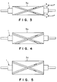
- the strength members 3 laid-up on the auxiliary member 2 can be formed in accordance with three-stage process as shown in Figs. 3 to 5.
- auxiliary member e.g., Teflon tape ("Teflon” is the trademark for polytetrafluoroethylene)
- a strength member 3a (which corresponds to 1/3 of all the plies) composed of the carbon fiber reinforced plastic composite material and a glass fiber reinforced plastic composite material (as a cushioning composite material) is laid up in the laminating direction of ⁇ 17 degrees with respect to the axial line of the forming mandrel 1.
- the proportion of the carbon fiber reinforced plastic composite material as a major material and the glass fiber reinforced plastic composite material as a cushioning material can be decided in accordance with a complex rule so as to satisfy the required strength and elastic modulus.
- the strength member 3a laid up on the auxiliary member 2 of the forming mandrel 1 is processed for compaction at 100°C under 6kgf/cm 2 for 30min., in order to secure the cylindrical shape and to prevent the occurrence of the local meandering and local wrinkles.
- the other strength member 3c of about 1/3 of all the plies is further laid up.
- the strength member 3c laid up on the strength member 3b is heated for curing at 165°C for 240min., in order to obtain a cylindrical part having a thick wall and manufactured by the carbon fiber reinforced plastic composite material.
- compaction conditions pressure, temperature, time, the number of times
- pressure, temperature, time, the number of times are determined within a range in which no harmful influence is exerted upon the physical properties of the cylindrical part having a thick wall manufactured by the composite material and cured finally.
- the fiber reinforced plastic composite material for form the strength member 3 is laminated three times separately.
- one layer of the glass fiber reinforced plastic composite material is laid up between the fiber reinforced plastic composite material at regular intervals.
- the strength member 3 is processed for compaction at 100°C under 6kgf/cm 2 for 30min.
- the number of the lamination layers of the strength members 3 and the compaction processing timings are as follows:
- the cylindrical part was heated for curing at 165°C under 6kgf/cm 2 for 240min.
- This temperature condition is lower than that of the conventional conditions as 180°C under 6kgf/cm 2 for 120min.. Since the heat curing temperature is lowered, the difference between the heating temperature and the room temperature can be reduced, so that the thermal stress can be decreased. Further, it was confirmed that the performance of the composite material is not changed due to the change in curing conditions. In more details, test pieces were heat-cured at 165°C for 240min., and further it was confirmed that these test pieces were not changed at the glass transition point temperature.
- test piece was equivalent to that of a test piece cured at 180°C for 120min., by measuring the water absorption quantity of these test pieces.
- test pieces to each of which the final heat-curing process was made were tested for strength. It was confirmed that the strength was not reduced.
- the final heat-curing conditions were decided.
- the above-mentioned compaction processing is made to secure the true cylindrical shape and to prevent the occurrence of local meandering and local wrinkles.
- These conditions can be decided within a range where the physical properties of the composite material do not deteriorate after the final heat curing, on the basis of such a temperature standard that the plastic begins to flow and such time standard that the plastic is not yet cured by heat.
- the conditions of the compaction processing is decided on the basis of the property examination of the plastic after compaction processing and the strength test results of the plastic after the final heat-curing.
- the decided compaction conditions are as follows: the temperature is 60 to 130°C, and the pressure is 3 to 6kgf/cm 2 of the ordinary heat curing conditions.
- Table 1 lists the relationship between the curing conditions and the physical properties.
- Table 1 CURING CONDITIONS AND PROPERTIES CURING CONDITIONS BENDING STRENGTH (kgf/mm 2 ) BENDING MODULUS (kgf/mm 2 )
- GLASS TRANSIT TEMP Tg (°C) WATER ABSORB RATIO (%) 180°Cx120min. 213 12,300 195 0.43 165° Cx240min. 206 12,300 191 0.41
- the major material is the carbon fiber reinforced plastic (CFRP) and the cushioning material is glass fiber reinforced plastic (GFRP).
- CFRP carbon fiber reinforced plastic
- GFRP glass fiber reinforced plastic
- the proportion of both is 9 : 1 on the basis of the requirement of strength and rigidity.
- the lamination orientation is of unidirection of ⁇ 17° (100%). This unidirectional lamination orientation has the bending strength and the rigidity both equivalent to those of the cylindrical parts manufactured by the composite material having the lamination orientation of ⁇ 10° (65%) / ⁇ 45° (25%) / ⁇ 85° (10%).
- Fig. 7 shows the analysis results (NASTRAN) of the internal stress of the thick-walled cylindrical part manufactured by composite material, which are obtained after cured in the curing cycle.
- a solid curve shows an internal stress change obtained by the thick-walled cylindrical part manufactured by composite material having the lamination orientation of the unidirection of ⁇ 17° (100%) and the curing temperature of 165°C
- a dashed-line curve shows an internal stress change obtained by the thick-walled cylindrical part manufactured by composite material having the lamination orientation of ⁇ 10° (65%) / ⁇ 45° (25%) / ⁇ 85° (10%) and the curing temperature of 180°C
- a dot-dashed-line curve shows an internal stress change obtained by the thick-walled cylindrical part manufactured by composite material having the lamination orientation of ⁇ 10° (65%) / ⁇ 45° (25%) / ⁇ 85° (10%) and the curing temperature of 165°C.
- the proportion of the carbon fiber reinforced plastic composite material to the glass fiber reinforced plastic composite material both for forming the lamination orientation of the thick-walled cylindrical part manufactured by composite material is 9 : 1.
- the lamination directions of ⁇ 10° and ⁇ 45° are applied to the carbon fiber reinforced plastic composite material and the laminating direction of ⁇ 85° is applied to the glass fiber reinforced plastic composite material.
- the number of the laminated layers and the timings of the compaction process are as follows:
- Fig. 7 indicates that in the case of the thick-walled cylindrical part manufactured by composite material as shown by the solid line curve, it is possible to reduce the internal stress largely by reducing the curing temperature and by determining only one laminating direction.
- Table 2 lists the experimental results of the interlayer separation of the thick-walled cylindrical part manufactured by the method according to the present invention, in comparison with those of the interlayer separation manufactured by the other methods.
- Table 2 PRESENCE OR ABSENCE OF INTERLAYER SEPARATION ACCORDING TO MANUFACTURING METHODS NO T A B C D LAMINATION ORIENTATION E 1 11 NO NO NO 180 ⁇ 10°/ ⁇ 45°/ ⁇ 85° NO 2 30 NO NO NO 180 ⁇ 10°/ ⁇ 45°/ ⁇ 85° YES 3 30 YES YES NO 180 ⁇ 10°/ ⁇ 45°/ ⁇ 85° NO 4 42 YES YES NO 180 ⁇ 10°/ ⁇ 45°/ ⁇ 85° YES 5 42 YES YES YES 165 ⁇ 10°/ ⁇ 45°/ ⁇ 85° YES 6 42 YES YES YES 165 ⁇ 17° NO T: THICKNESS (mm)
- the number of the laminated layers of the strength member of the thick-walled cylindrical part and the timing of the compaction processing were as follows: Further, the laminating directions of ⁇ 10° and ⁇ 45° were applied to the carbon fiber reinforced plastic composite material and the lamination direction of ⁇ 85° was applied to the glass fiber reinforced plastic composite material.
- the laminating orientation was of unidirection of ⁇ 17°; the cushioning material was applied; the heat compaction process was made; the auxiliary member was applied; and further the curing temperature was lowered to 165°C. Therefore, it was possible to obtain the cylindrical parts of excellent quality having no interlayer separation.
- the present invention has been explained by taking the case where the internal diameter of the cylindrical part is decoded as 80mm (radius: 40mm) as shown in Fig. 7.
- the limit of the wall thickness is not yet confirmed. Therefore, when the limit of the wall thickness is confirmed, it may be possible to obtain the thick-walled cylindrical part other than those as listed in Table 2. Further, when the internal diameter of the cylindrical part changes, even if the wall thickness is not changed, the internal stress differs. Therefore, when the manufacturing method according to the present invention is adopted by changing the internal diameter of the cylindrical part, it may be possible to obtain the cylindrical part having the wall thickness partially different from the values as listed in Table 2.
- the technical scope of the present invention includes the manufacturing method in which the internal diameter is changed, without being limited to only the internal diameter of 80mm.
- the method according to the present invention it is possible to manufacturing the thick-walled cylindrical part having an excellent quality, by using the fiber reinforced plastic composite material, and by reducing the internal stress generated after heat curing process.
Landscapes
- Engineering & Computer Science (AREA)
- Mechanical Engineering (AREA)
- Chemical & Material Sciences (AREA)
- Composite Materials (AREA)
- Manufacturing & Machinery (AREA)
- Moulding By Coating Moulds (AREA)
Applications Claiming Priority (3)
| Application Number | Priority Date | Filing Date | Title |
|---|---|---|---|
| JP15245896 | 1996-06-13 | ||
| JP152458/96 | 1996-06-13 | ||
| JP15245896A JPH10693A (ja) | 1996-06-13 | 1996-06-13 | 繊維強化樹脂複合材製円筒部品およびその製造方法 |
Publications (3)
| Publication Number | Publication Date |
|---|---|
| EP0812673A2 true EP0812673A2 (de) | 1997-12-17 |
| EP0812673A3 EP0812673A3 (de) | 1999-05-12 |
| EP0812673B1 EP0812673B1 (de) | 2002-08-21 |
Family
ID=15540965
Family Applications (1)
| Application Number | Title | Priority Date | Filing Date |
|---|---|---|---|
| EP19970109705 Expired - Lifetime EP0812673B1 (de) | 1996-06-13 | 1997-06-13 | Zylindrischer Gegenstand aus faserverstärktem Verbundwerkstoff und Verfahren zu dessen Herstellung |
Country Status (7)
| Country | Link |
|---|---|
| US (3) | US5985073A (de) |
| EP (1) | EP0812673B1 (de) |
| JP (1) | JPH10693A (de) |
| KR (1) | KR100237256B1 (de) |
| CN (1) | CN1134331C (de) |
| CA (1) | CA2207495C (de) |
| DE (1) | DE69714814T2 (de) |
Cited By (3)
| Publication number | Priority date | Publication date | Assignee | Title |
|---|---|---|---|---|
| WO2012021958A1 (pt) * | 2010-08-17 | 2012-02-23 | Marco Antonio Rodrigues Souza | Processo para fabricação de estrutura compósita utilizando enrolamento filamentar com resinas termoplásticas |
| DE102013108259A1 (de) * | 2013-08-01 | 2015-02-05 | Thyssenkrupp Ag | Verfahren zur Herstellung rohrförmiger Faserverbundkörper |
| CN110653972A (zh) * | 2019-09-29 | 2020-01-07 | 郑豪 | 一种碳纤维管成型装置及碳纤维管 |
Families Citing this family (33)
| Publication number | Priority date | Publication date | Assignee | Title |
|---|---|---|---|---|
| JPH10693A (ja) * | 1996-06-13 | 1998-01-06 | Fuji Heavy Ind Ltd | 繊維強化樹脂複合材製円筒部品およびその製造方法 |
| US6620510B1 (en) * | 1998-12-25 | 2003-09-16 | Mitsubishi Rayon Co., Ltd. | Epoxy resin composition, prepreg, and roll made of resin reinforced with reinforcing fibers |
| KR100760168B1 (ko) * | 1999-06-09 | 2007-09-20 | 신닛뽄세키유 가부시키가이샤 | 반송용 부재 |
| US7080573B2 (en) * | 2000-10-20 | 2006-07-25 | Toray Composites (America), Inc. | Hybrid composite flywheel rim and its manufacturing method |
| DE10123809A1 (de) * | 2001-05-16 | 2002-11-21 | Voith Paper Patent Gmbh | Durchströmzylinder |
| US6852401B2 (en) | 2001-09-13 | 2005-02-08 | Beacon Power Corporation | Composite flywheel rim with co-mingled fiber layers and methods for manufacturing same |
| US20040076809A1 (en) * | 2001-09-13 | 2004-04-22 | Spears Ward R. | Composite flywheel rim having commingled layers with macroscopically uniform patterns of fiber arrangement and methods for manufacturing same |
| US6824861B2 (en) | 2001-09-13 | 2004-11-30 | Beacon Power Corporation | Composite flywheel rim with co-mingled fiber layers and methods for manufacturing same |
| KR100828806B1 (ko) * | 2006-08-04 | 2008-05-09 | 현대자동차주식회사 | 자동차용 하이브리드 드라이브샤프트의 제조방법 |
| JP2009180292A (ja) * | 2008-01-30 | 2009-08-13 | Showa Corp | フロントフォーク用アウタチューブ |
| JP4886710B2 (ja) * | 2008-01-30 | 2012-02-29 | 株式会社ショーワ | フロントフォーク用アウタチューブ |
| CN102019690A (zh) * | 2010-10-09 | 2011-04-20 | 谢晓建 | 一种长纤维增强热固性塑料压力膜壳的制造方法 |
| CN102092139B (zh) * | 2010-12-29 | 2013-03-27 | 哈尔滨玻璃钢研究院 | 纤维缠绕成型的复合材料传动管坯的制备方法 |
| EP2511084B1 (de) * | 2011-04-14 | 2014-11-12 | Magna Steyr Fahrzeugtechnik AG & Co KG | Knotenelement aus faserverstärktem Kunststoff sowie Herstellungsverfahren und Verwendung dafür |
| AU2012339553B2 (en) | 2011-11-16 | 2016-05-12 | Flexpipe Systems Inc. | Flexible reinforced pipe and reinforcement tape |
| EP2780619B1 (de) | 2011-11-16 | 2018-09-05 | Shawcor Ltd. | Rohrverbindungsanordnung und verfahren |
| US9857003B2 (en) | 2012-02-17 | 2018-01-02 | Core Linepipe Inc. | Pipe, pipe connection and pipeline system |
| CN103042702B (zh) * | 2012-11-13 | 2015-01-07 | 中国科学院宁波材料技术与工程研究所 | 减少纤维增强热塑性复合材料制品表面缺陷的方法 |
| US9464685B2 (en) * | 2013-02-07 | 2016-10-11 | Orbital Atk, Inc. | Composite dome connectors for flywheel rim to shaft attachment |
| KR101587117B1 (ko) * | 2014-04-29 | 2016-01-21 | 전주대학교산학협력단 | 냉동탑차 적재함 고정용 복합재 각관 및 이의 제조방법 |
| KR101714164B1 (ko) * | 2015-07-01 | 2017-03-23 | 현대자동차주식회사 | 차량용 복합재 멤버 및 그 제조방법 |
| DE102015225690A1 (de) * | 2015-12-17 | 2017-06-22 | Bayerische Motoren Werke Aktiengesellschaft | Druckbehälter mit Endlosfasern |
| CN107599461A (zh) * | 2017-08-04 | 2018-01-19 | 镇江春环密封件集团有限公司 | 一种聚四氟乙烯薄膜成型方法 |
| CN108454078A (zh) * | 2018-03-02 | 2018-08-28 | 关清英 | 一种玻璃钢的缠绕成型方法 |
| CN108481759A (zh) * | 2018-03-09 | 2018-09-04 | 浙江鸿道环保有限公司 | 一种新型排渗管的制作方法 |
| US11761208B2 (en) * | 2018-06-25 | 2023-09-19 | Carbo-Link Ag | Anchor sleeve and anchor system |
| CN109571984B (zh) * | 2018-11-12 | 2020-12-29 | 中国航空工业集团公司基础技术研究院 | 一种长纤维增强复合材料管件的制造工艺方法 |
| CN110370686B (zh) * | 2019-08-13 | 2021-03-12 | 核工业第八研究所 | 一种双复合材料增强环制作工艺 |
| CN112976615B (zh) * | 2019-12-17 | 2023-06-30 | 财团法人金属工业研究发展中心 | 热塑复材管的制造装置及制造方法 |
| CN112571835B (zh) * | 2020-10-30 | 2022-09-27 | 航天材料及工艺研究所 | 一种适应于自动倾斜铺放的高效示教编程工艺方法 |
| KR102392124B1 (ko) * | 2021-03-02 | 2022-04-28 | 주식회사 광명산업 | Frp 코어 보강방법 |
| KR102384781B1 (ko) * | 2021-03-02 | 2022-04-08 | 주식회사 광명산업 | 고강도 코어 제조장치와 그 방법 및 이들에 의해 제조된 코어 |
| KR102373344B1 (ko) * | 2021-03-02 | 2022-03-11 | 주식회사 광명산업 | Frp 2중 코어 제조장치 |
Family Cites Families (22)
| Publication number | Priority date | Publication date | Assignee | Title |
|---|---|---|---|---|
| US2723705A (en) * | 1950-07-21 | 1955-11-15 | Owens Corning Fiberglass Corp | Method and apparatus for making reinforced plastic laminates |
| US2753705A (en) | 1955-07-01 | 1956-07-10 | Harry C Quartier | Self-wetting wick composition |
| US3602067A (en) * | 1969-09-18 | 1971-08-31 | United Aircraft Corp | Flywheel |
| DE2142015A1 (de) * | 1970-09-10 | 1972-04-13 | Westland Aircraft Ltd | Verfahren zum Verdichten von aus Fäden oder Band gewickelten rohrförmigen Gegenständen |
| US4089190A (en) * | 1976-04-14 | 1978-05-16 | Union Carbide Corporation | Carbon fiber drive shaft |
| US4273601A (en) * | 1977-10-31 | 1981-06-16 | Structural Composites Industries, Inc. | Method for the production of elongated resin impregnated filament composite structures |
| EP0009007B1 (de) * | 1978-09-07 | 1982-06-23 | Ciba-Geigy Ag | Verfahren zur Herstellung eines faserverstärkten Kunststoffrohres und nach dem Verfahren hergestelltes Rohr |
| JPS5593418A (en) * | 1979-01-11 | 1980-07-15 | Sumitomo Electric Ind Ltd | Preparation of fiber reinforced plastic cylinder |
| JPS5734085A (en) * | 1980-08-06 | 1982-02-24 | Toho Beslon Co | Manufacture of carbon fiber reinforced carbon composite material |
| US4591400A (en) * | 1984-05-15 | 1986-05-27 | United Technologies Corporation | Method of forming a fiber reinforced composite article of a complex configuration |
| JPS6428846A (en) * | 1987-07-24 | 1989-01-31 | Hitachi Ltd | Socket for ic |
| JPH01148545A (ja) * | 1987-12-04 | 1989-06-09 | Ube Ind Ltd | 層間ハイブリッド積層材 |
| JPH01288692A (ja) * | 1988-05-17 | 1989-11-20 | Yokohama Rubber Co Ltd:The | 繊維強化樹脂管 |
| JPH02236014A (ja) * | 1989-03-09 | 1990-09-18 | Sumitomo Metal Ind Ltd | 繊維強化プラスチック製駆動軸 |
| JPH0798365B2 (ja) * | 1989-11-27 | 1995-10-25 | 日本電気株式会社 | 繊維強化複合材料の作製方法 |
| US5261462A (en) * | 1991-03-14 | 1993-11-16 | Donald H. Wolfe | Flexible tubular structure |
| JPH0584836A (ja) * | 1991-09-25 | 1993-04-06 | Toyota Motor Corp | 複合円筒部材の製造方法 |
| FR2684578B1 (fr) * | 1991-12-04 | 1996-04-12 | Snecma | Procede de fabrication de pieces en materiau composite a matrice metallique |
| US5549947A (en) * | 1994-01-07 | 1996-08-27 | Composite Development Corporation | Composite shaft structure and manufacture |
| US5266139A (en) * | 1992-10-02 | 1993-11-30 | General Dynamics Corporation, Space Systems Division | Continuous processing/in-situ curing of incrementally applied resin matrix composite materials |
| JP3009311B2 (ja) * | 1993-08-04 | 2000-02-14 | 東邦レーヨン株式会社 | 繊維強化樹脂製コイルスプリングおよびその製造方法 |
| JPH10693A (ja) * | 1996-06-13 | 1998-01-06 | Fuji Heavy Ind Ltd | 繊維強化樹脂複合材製円筒部品およびその製造方法 |
-
1996
- 1996-06-13 JP JP15245896A patent/JPH10693A/ja active Pending
-
1997
- 1997-06-05 US US08/870,419 patent/US5985073A/en not_active Expired - Fee Related
- 1997-06-11 CA CA 2207495 patent/CA2207495C/en not_active Expired - Fee Related
- 1997-06-12 KR KR1019970024230A patent/KR100237256B1/ko not_active Expired - Fee Related
- 1997-06-13 EP EP19970109705 patent/EP0812673B1/de not_active Expired - Lifetime
- 1997-06-13 CN CNB97114916XA patent/CN1134331C/zh not_active Expired - Fee Related
- 1997-06-13 DE DE69714814T patent/DE69714814T2/de not_active Expired - Fee Related
-
1998
- 1998-09-23 US US09/158,894 patent/US6670005B2/en not_active Expired - Fee Related
-
1999
- 1999-07-06 US US09/348,014 patent/US6299718B1/en not_active Expired - Fee Related
Cited By (3)
| Publication number | Priority date | Publication date | Assignee | Title |
|---|---|---|---|---|
| WO2012021958A1 (pt) * | 2010-08-17 | 2012-02-23 | Marco Antonio Rodrigues Souza | Processo para fabricação de estrutura compósita utilizando enrolamento filamentar com resinas termoplásticas |
| DE102013108259A1 (de) * | 2013-08-01 | 2015-02-05 | Thyssenkrupp Ag | Verfahren zur Herstellung rohrförmiger Faserverbundkörper |
| CN110653972A (zh) * | 2019-09-29 | 2020-01-07 | 郑豪 | 一种碳纤维管成型装置及碳纤维管 |
Also Published As
| Publication number | Publication date |
|---|---|
| EP0812673A3 (de) | 1999-05-12 |
| US5985073A (en) | 1999-11-16 |
| JPH10693A (ja) | 1998-01-06 |
| CA2207495C (en) | 2000-08-22 |
| DE69714814D1 (de) | 2002-09-26 |
| EP0812673B1 (de) | 2002-08-21 |
| DE69714814T2 (de) | 2003-05-28 |
| CN1169910A (zh) | 1998-01-14 |
| KR980000863A (ko) | 1998-03-30 |
| CN1134331C (zh) | 2004-01-14 |
| US6299718B1 (en) | 2001-10-09 |
| US20010008163A1 (en) | 2001-07-19 |
| KR100237256B1 (ko) | 2000-01-15 |
| CA2207495A1 (en) | 1997-12-13 |
| US6670005B2 (en) | 2003-12-30 |
Similar Documents
| Publication | Publication Date | Title |
|---|---|---|
| EP0812673A2 (de) | Zylindrischer Gegenstand aus faserverstärktem Verbundwerkstoff und Verfahren zu dessen Herstellung | |
| Albert et al. | Spring-in and warpage of angled composite laminates | |
| US8523553B2 (en) | Apparatus for forming hat stiffened composite parts using thermally expansive tooling cauls | |
| US5145621A (en) | Crossover mold tool for consolidating composite material | |
| Jeronimidis et al. | Residual stresses in carbon fibre-thermoplastic matrix laminates | |
| JPS6172538A (ja) | 中空体の製造方法 | |
| Huang et al. | Warping in advanced composite tools with varying angles and radii | |
| Jain et al. | Spring-in study of the aileron rib manufactured from advanced thermoplastic composite | |
| CA1311595C (en) | Process and equipment for making composite tubes | |
| Uemura et al. | Thermal residual stresses in filament-wound carbon-fiber-reinforced composites | |
| CN118980000A (zh) | 一种抗高温高压的复合管道及成型工艺 | |
| Whitney et al. | Design and fabrication of tubular specimens for composite characterization | |
| Fernlund et al. | Residual stress, spring-in and warpage in autoclaved composite parts | |
| CN105522326B (zh) | 使用纤维转向的复合层压板的热膨胀调节系数 | |
| Choo et al. | Influence of radial compressive stress owing to pressure on the failure modes of composite tube specimens | |
| EP0577409A1 (de) | Rohrartiges, faserverstärktes Kunststoffbaumaterial und Verfahren zur Herstellung | |
| JPS6168232A (ja) | 曲がり管の製造方法 | |
| Tarnopol'skii et al. | Carrying capacity of rings formed by winding composites with high-modulus anisotropic fiber reinforcement | |
| Tzeng | Predictions and experimental verification of residual stresses in thermoplastic composite cylinders | |
| Galletly et al. | Buckling of slightly flattened domed ends reinforced locally with fibre-reinforced plastic | |
| CN115891200B (zh) | 复合材料试验件制造方法及复合材料试验件 | |
| Foley et al. | Use of torsion tubes to measure in-plane shear properties of filament-wound composites | |
| US6139670A (en) | Method of making golf clubs of thermoplastic composite material | |
| US20220097318A1 (en) | Pressurizing device, and method and apparatus for manufacturing fiber reinforced resin pipe using pressurizing device | |
| Oakeshott | Warpage of carbon–epoxy composite channels |
Legal Events
| Date | Code | Title | Description |
|---|---|---|---|
| PUAI | Public reference made under article 153(3) epc to a published international application that has entered the european phase |
Free format text: ORIGINAL CODE: 0009012 |
|
| 17P | Request for examination filed |
Effective date: 19970703 |
|
| AK | Designated contracting states |
Kind code of ref document: A2 Designated state(s): DE FR GB IT |
|
| RTI1 | Title (correction) | ||
| PUAL | Search report despatched |
Free format text: ORIGINAL CODE: 0009013 |
|
| AK | Designated contracting states |
Kind code of ref document: A3 Designated state(s): AT BE CH DE DK ES FI FR GB GR IE IT LI LU MC NL PT SE |
|
| AKX | Designation fees paid |
Free format text: DE FR GB IT |
|
| 17Q | First examination report despatched |
Effective date: 20000620 |
|
| GRAG | Despatch of communication of intention to grant |
Free format text: ORIGINAL CODE: EPIDOS AGRA |
|
| GRAG | Despatch of communication of intention to grant |
Free format text: ORIGINAL CODE: EPIDOS AGRA |
|
| GRAH | Despatch of communication of intention to grant a patent |
Free format text: ORIGINAL CODE: EPIDOS IGRA |
|
| GRAH | Despatch of communication of intention to grant a patent |
Free format text: ORIGINAL CODE: EPIDOS IGRA |
|
| GRAA | (expected) grant |
Free format text: ORIGINAL CODE: 0009210 |
|
| AK | Designated contracting states |
Kind code of ref document: B1 Designated state(s): DE FR GB IT |
|
| REG | Reference to a national code |
Ref country code: GB Ref legal event code: FG4D |
|
| REF | Corresponds to: |
Ref document number: 69714814 Country of ref document: DE Date of ref document: 20020926 |
|
| ET | Fr: translation filed | ||
| PLBE | No opposition filed within time limit |
Free format text: ORIGINAL CODE: 0009261 |
|
| STAA | Information on the status of an ep patent application or granted ep patent |
Free format text: STATUS: NO OPPOSITION FILED WITHIN TIME LIMIT |
|
| 26N | No opposition filed |
Effective date: 20030522 |
|
| PGFP | Annual fee paid to national office [announced via postgrant information from national office to epo] |
Ref country code: FR Payment date: 20040608 Year of fee payment: 8 |
|
| PGFP | Annual fee paid to national office [announced via postgrant information from national office to epo] |
Ref country code: GB Payment date: 20040609 Year of fee payment: 8 |
|
| PGFP | Annual fee paid to national office [announced via postgrant information from national office to epo] |
Ref country code: DE Payment date: 20040624 Year of fee payment: 8 |
|
| PG25 | Lapsed in a contracting state [announced via postgrant information from national office to epo] |
Ref country code: IT Free format text: LAPSE BECAUSE OF NON-PAYMENT OF DUE FEES;WARNING: LAPSES OF ITALIAN PATENTS WITH EFFECTIVE DATE BEFORE 2007 MAY HAVE OCCURRED AT ANY TIME BEFORE 2007. THE CORRECT EFFECTIVE DATE MAY BE DIFFERENT FROM THE ONE RECORDED. Effective date: 20050613 Ref country code: GB Free format text: LAPSE BECAUSE OF NON-PAYMENT OF DUE FEES Effective date: 20050613 |
|
| PG25 | Lapsed in a contracting state [announced via postgrant information from national office to epo] |
Ref country code: DE Free format text: LAPSE BECAUSE OF NON-PAYMENT OF DUE FEES Effective date: 20060103 |
|
| PG25 | Lapsed in a contracting state [announced via postgrant information from national office to epo] |
Ref country code: FR Free format text: LAPSE BECAUSE OF NON-PAYMENT OF DUE FEES Effective date: 20060228 |
|
| GBPC | Gb: european patent ceased through non-payment of renewal fee |
Effective date: 20050613 |
|
| REG | Reference to a national code |
Ref country code: FR Ref legal event code: ST Effective date: 20060228 |