EP0811518B1 - Fahrzeug, insbesondere mit einem einklappbarem Dach - Google Patents
Fahrzeug, insbesondere mit einem einklappbarem Dach Download PDFInfo
- Publication number
- EP0811518B1 EP0811518B1 EP97106765A EP97106765A EP0811518B1 EP 0811518 B1 EP0811518 B1 EP 0811518B1 EP 97106765 A EP97106765 A EP 97106765A EP 97106765 A EP97106765 A EP 97106765A EP 0811518 B1 EP0811518 B1 EP 0811518B1
- Authority
- EP
- European Patent Office
- Prior art keywords
- roof part
- hinge device
- roof
- vehicle according
- vehicle
- Prior art date
- Legal status (The legal status is an assumption and is not a legal conclusion. Google has not performed a legal analysis and makes no representation as to the accuracy of the status listed.)
- Expired - Lifetime
Links
- 230000000712 assembly Effects 0.000 description 2
- 238000000429 assembly Methods 0.000 description 2
- 230000000694 effects Effects 0.000 description 2
- 238000000034 method Methods 0.000 description 2
- 230000006978 adaptation Effects 0.000 description 1
- 230000005540 biological transmission Effects 0.000 description 1
- 230000015572 biosynthetic process Effects 0.000 description 1
- 238000010276 construction Methods 0.000 description 1
- 238000009434 installation Methods 0.000 description 1
- 210000000056 organ Anatomy 0.000 description 1
- 238000012856 packing Methods 0.000 description 1
- 230000002787 reinforcement Effects 0.000 description 1
- 238000007789 sealing Methods 0.000 description 1
- 230000001360 synchronised effect Effects 0.000 description 1
Images


Classifications
-
- B—PERFORMING OPERATIONS; TRANSPORTING
- B60—VEHICLES IN GENERAL
- B60J—WINDOWS, WINDSCREENS, NON-FIXED ROOFS, DOORS, OR SIMILAR DEVICES FOR VEHICLES; REMOVABLE EXTERNAL PROTECTIVE COVERINGS SPECIALLY ADAPTED FOR VEHICLES
- B60J7/00—Non-fixed roofs; Roofs with movable panels, e.g. rotary sunroofs
- B60J7/08—Non-fixed roofs; Roofs with movable panels, e.g. rotary sunroofs of non-sliding type, i.e. movable or removable roofs or panels, e.g. let-down tops or roofs capable of being easily detached or of assuming a collapsed or inoperative position
- B60J7/12—Non-fixed roofs; Roofs with movable panels, e.g. rotary sunroofs of non-sliding type, i.e. movable or removable roofs or panels, e.g. let-down tops or roofs capable of being easily detached or of assuming a collapsed or inoperative position foldable; Tensioning mechanisms therefor, e.g. struts
- B60J7/14—Non-fixed roofs; Roofs with movable panels, e.g. rotary sunroofs of non-sliding type, i.e. movable or removable roofs or panels, e.g. let-down tops or roofs capable of being easily detached or of assuming a collapsed or inoperative position foldable; Tensioning mechanisms therefor, e.g. struts with a plurality of rigid plate-like elements or rigid non plate-like elements, e.g. with non-slidable, but pivotable or foldable movement
- B60J7/143—Non-fixed roofs; Roofs with movable panels, e.g. rotary sunroofs of non-sliding type, i.e. movable or removable roofs or panels, e.g. let-down tops or roofs capable of being easily detached or of assuming a collapsed or inoperative position foldable; Tensioning mechanisms therefor, e.g. struts with a plurality of rigid plate-like elements or rigid non plate-like elements, e.g. with non-slidable, but pivotable or foldable movement for covering the passenger compartment
- B60J7/145—Non-fixed roofs; Roofs with movable panels, e.g. rotary sunroofs of non-sliding type, i.e. movable or removable roofs or panels, e.g. let-down tops or roofs capable of being easily detached or of assuming a collapsed or inoperative position foldable; Tensioning mechanisms therefor, e.g. struts with a plurality of rigid plate-like elements or rigid non plate-like elements, e.g. with non-slidable, but pivotable or foldable movement for covering the passenger compartment at least two elements being folded in clamp-shell fashion
Definitions
- the invention relates to a vehicle in particular a retractable roof in the form of a two-part Folding top according to the preamble of the claim 1.
- a folding roof with at least one front roof part and one rear roof part defining roof structure provided, the between the in a closed or open position pivotable roof parts an articulated connection having.
- an articulated connection having.
- Intermediate piece and a flexible reinforcement strip as Additional components arranged between the roof parts, so that this roof part connection is structurally complex and the roof parts in complex handling only in one small swivel angle range are movable.
- the invention is based, with a vehicle in particular to form a retractable roof so that the hinge connection in the area of the roof parts with little technical effort to a large swivel angle a space-saving packing layer enables and without interference the handling of the vehicle interior the convertible top can be opened and closed facilitated.
- the vehicle according to the invention has in the area of its two-part roof on an articulated connection, the individual components with one especially independent of the convertible top drive controllable drive element are connected that a directly driven hinge device for Roof part movement is formed.
- This hinge device enables in a confined space and largely with that Components that can be integrated into the vehicle roof can be pivoted the roof parts over an angle of more than 180 °, whereby the control of the drive member of the device with a rear-side convertible top drive can be synchronized can that in each movement phase in the pivot points of the Hinge parts and on the roof parts an optimal load Adjustment of positioning force and positioning speed is possible and thus a material-saving folding process for both hardtop roofs and roofs with in areas of flexible roof skin is achieved.
- the driven swivel members both one stable support of the front roof part during the Opening pivoting movement as well as precise guidance enable positioning in the closed position.
- the two roof parts are in the area the hinge device is stable in position spent that both in a front closing area towards the windshield frame as well as in one rear movement gap between the roof parts with sufficient Security a sealing engagement is reached.
- About a corresponding arrangement of the swivel axes Device can do this with little constructive effort adapted to different pivoting areas of the roof parts and their common trajectory also at simultaneous lifting and swiveling phase with precise guidance be run through.
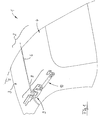
- the roof 2 as movable folding parts connected to the vehicle body has front roof part 3 and a rear roof part 4, these roof parts 3, 4 in the area perpendicular to Vehicle longitudinal axis 5 extending transverse axis 6 with a a closed or open position (Fig. 3 or Fig. 6) of the folding roof 2 enabling articulation are provided.
- the joint connection according to the invention between the roof parts 3 and 4 is designated as a total of 8 Hinge device formed, the pivot members 9th operable with at least one controllable drive element 10 are.
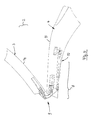
- FIG. 2 illustrates that the two roof parts 3 and 4 with two hinge devices 8, 8 'in the region of the transverse axis 6 are provided, these hinge devices 8, 8 'as identical assemblies symmetrical to the vehicle's longitudinal axis 5 near the side edges 11, 12 of the vehicle 1 are arranged. It is also conceivable that only one driven hinge device between the roof parts 3, 4 to be provided, for example in the area of Longitudinal vehicle axis 5 can be arranged (not shown) or the hinge devices in one too not shown embodiment with a common Drive element and transmission elements effective on both sides to provide.
- FIG. 3 to 6 show respective sectional representations of the vehicle 1, the two roof parts 3, 4 in side views, starting from a closed position according to Fig. 3 each different phases of movement Folding process of the two roof parts 3, 4 under the effect of driven hinge device 8 become clear.
- In 6 is the front roof part 3 with its top 14 to the top 15 of the rear roof part 4 shifted.
- the special constructive Formation of the pivot members 9 on the invention Hinge device 8 defines one controlled cam track (arrow K in Fig. 12) with a Swivel angle S between the two roof parts 3, 4.
- This pivot angle S can be more than 180 ° (additional angle S '), so that an approximation of the roof parts 3, 4 according to their profile in the area of Top 14, 15 possible and a space-saving pack layer is reached.
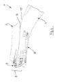
- the enlarged individual representation according to FIG. 7 shows the Hinge device 8 with the pivot members 9 in one Exploded view, wherein as pivot members 9 two each four connecting axes A, B, C, D and A ', B', C ', D' having four joints are provided, the individual elements effective together in the link chain are.
- the two four joints A, B, C, D and A ', B', C ', D' are in an appropriate design via a wishbone 16 connected to the thrust movement of the drive member 10 (arrow 17) between the two four-bar joints is coupled.
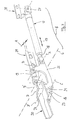
- FIGS. 9 to 12 clarify that a push rod 18 of the appropriate design drive organ designed as a working cylinder 10 on a connecting axis A of a fork link 20 attacks, the first leg 19 on the rear Roof part 4 is supported in the connecting axis B.
- the Fork link 20 has a second leg 21, the ends directly on the front roof part 3 in the area of Axis D is supported.
- the fork handlebar 20 is also in Area of his second leg 21 in a connecting axis C with the second four-bar link over the wishbone 16 connected.
- the second four-bar linkage A ', B', C ', D' has one in the middle Area of the wishbone 16 in the area of the axis A ' attacking and on the rear roof part 4 in the axis B ' supported bow swinging part 23 on and in the area of Axis C 'is on the wishbone 16 with the front roof part 3 rocker arm 24 connected in the area of the axis D ' intended.
- FIGS. 10 to 12 illustrate different pivot positions of the Swivel members 9 and the roof parts 3 and 4, wherein under Effect of the pivoting device 8 in the front roof part 3 Area of an existing movement gap to the rear roof part 4 25 in the manner of a wide-angle movement Curve path K (Fig. 12) passes through such that a touch is excluded from roof parts and over a different design dimensions of the swivel links 9 overall an adaptation to different Component heights H, H 'of the roof part construction is possible.
- the drive element 10 designed as a working cylinder is on the cylinder side via a joint profile part 27 (FIG. 7) having holding plate 28 set on the roof parts 4 and the connecting axes B, B 'in the area of the swivel links 20 and 23 are from one on the underside of the roof part extending support strut 29 formed.
- the connecting axes D, D ' In the area of front roof part 3 are the connecting axes D, D ' an angle plate 30 is provided.
- Joints B, B 'and D, D' each by a distance A (Fig. 7) offset in the direction of the transverse axis 6 arranged to each other so that the hinge device 8th can be installed overall in an advantageously narrow installation space is.
- the hinge device 8, 8 'described above is on different operating conditions over a corresponding Design of their swivel members 9 and the drive member 10 so adaptable that, for example, doors and flaps as moving parts on assemblies of Vehicles, machines, structures or the like. Driven with this Hinge device 8, 8 'may be provided can.
Landscapes
- Engineering & Computer Science (AREA)
- Mechanical Engineering (AREA)
- Body Structure For Vehicles (AREA)
Description
- Fig. 1
- eine Prinzipdarstellung eines Fahrzeug-Teiles in Heckansicht mit einer Scharniervorrichtung zwischen einem vorderen und einem hinteren Dachteil,
- Fig. 2
- eine teilweise geschnittene Perspektivdarstellung des Fahrzeuges mit zwei jeweils randseitig an den insbesondere einstückigen, stabilen Dachteilen (Hardtop) angeordneten Scharniervorrichtungen,
- Fig. 3
- eine teilweise geschnittene Seitenansicht des Verdecks mit den beiden Dachteilen in Schließstellung ähnlich Fig. 1,
- Fig. 4 bis Fig. 6
- jeweilige Bewegungsphasen des vorderen Dachteils bei Betätigung des Scharniervorrichtung,
- Fig. 7
- eine vergrößerte Einzeldarstellung der erfindungsgemäßen Scharniervorrichtung in Perspektivdarstellung,
- Fig. 8
- eine Ausschnittsdarstellung der beiden Dachteile mit der Scharniervorrichtung in Draufsicht, und
- Fig. 9 bis Fig. 12
- jeweils vergrößerte Ausschnittsdarstellungen der Scharniervorrichtung in unterschiedlichen Bewegungsphasen (ähnlich Fig. 4 bis 6).
Claims (7)
- Fahrzeug mit zueinander bewegbaren Teilen, z.B. Türen und Klappen, mit einem einklappbaren Dach (2), das zumindest ein vorderes Dachteil (3) und ein hinteres Dachteil (4) aufweist, die zumindest eine eine Schließ- bzw. Öffnungsstellung ermöglichende Gelenkverbindung aufweisen, dadurch gekennzeichnet , daß die Gelenkverbindung als eine unmittelbar von einem steuerbaren Antriebsorgan (10) betätigbare Scharniervorrichtung (8, 8') ausgebildet ist.
- Fahrzeug nach Anspruch 1, dadurch gekennzeichnet, daß mittels der angetriebenen Scharniervorrichtung(en) (8, 8') das vordere Dachteil (3) mit seiner Oberseite (14) zur Oberseite (15) des hinteren Dachteils (4) hin verlagerbar ist.
- Fahrzeug nach Anspruch 1 oder 2, dadurch gekennzeichnet, daß die Scharniervorrichtung (8, 8') zwischen den beiden Dachteilen (3, 4) einen Schwenkwinkel (S) von mehr als 180° definiert.
- Fahrzeug nach einem der Ansprüche 1 bis 3, dadurch gekennzeichnet, daß die Scharniervorrichtung (8, 8') mehrere, eine Gelenkkette (A, B, C, D, A', B', C', D') mit zueinander versetzten Schwenkachsen definierende Schwenkglieder (9) aufweist.
- Fahrzeug nach einem der Ansprüche 1 bis 4, dadurch gekennzeichnet, daß die Scharniervorrichtung (8, 8') als Schwenkglieder (9) zwei über einen Querlenker (16) verbundene Viergelenke (A, B, C, D, A', B', C', D') aufweist.
- Fahrzeug nach einem der Ansprüche 1 bis 5, dadurch gekennzeichnet, daß das Antriebsorgan (10) der Scharniervorrichtung (8, 8') an einem am hinteren Dachteil (4) über einen ersten Schenkel (19) abgestützten Gabellenker (20) angreift, dessen zweiter Schenkel (21) endseitig direkt am vorderen Dachteil (3) abgestützt und außerdem mit dem zweiten Viergelenk (A', B', C', D') über den Querlenker (16) verbunden ist.
- Fahrzeug nach einem der Ansprüche 1 bis 6, dadurch gekennzeichnet, daß das zweite Viergelenk (A', B', C', D') von einem am Querlenker (16) im mittleren Bereich angreifenden sowie am hinteren Dachteil (4) abgestützten Bogenschwingteil (23) und einem endseitig am Querlenker (16) angreifenden sowie mit dem vorderen Dachteil (3) verbundenen Schwinghebel (24) gebildet ist.
Applications Claiming Priority (2)
| Application Number | Priority Date | Filing Date | Title |
|---|---|---|---|
| DE19623036 | 1996-06-08 | ||
| DE19623036A DE19623036A1 (de) | 1996-06-08 | 1996-06-08 | Fahrzeug, insbesondere mit einem einklappbarem Dach |
Publications (3)
| Publication Number | Publication Date |
|---|---|
| EP0811518A1 EP0811518A1 (de) | 1997-12-10 |
| EP0811518B1 true EP0811518B1 (de) | 2000-02-23 |
| EP0811518B2 EP0811518B2 (de) | 2006-08-23 |
Family
ID=7796483
Family Applications (1)
| Application Number | Title | Priority Date | Filing Date |
|---|---|---|---|
| EP97106765A Expired - Lifetime EP0811518B2 (de) | 1996-06-08 | 1997-04-24 | Fahrzeug, insbesondere mit einem einklappbarem Dach |
Country Status (3)
| Country | Link |
|---|---|
| US (1) | US5833300A (de) |
| EP (1) | EP0811518B2 (de) |
| DE (2) | DE19623036A1 (de) |
Families Citing this family (42)
| Publication number | Priority date | Publication date | Assignee | Title |
|---|---|---|---|---|
| US6042174A (en) | 1997-08-22 | 2000-03-28 | Asc Incorporated | Latching and control apparatus for an automotive vehicle convertible roof |
| FR2778610B1 (fr) * | 1998-05-12 | 2000-08-04 | France Design | Toit repliable en trois elements pour vehicule decouvrable |
| US6439642B2 (en) * | 1998-05-25 | 2002-08-27 | Dura Convertable Gmbh | Retractable hard top for passenger cars |
| US6269521B1 (en) * | 1998-09-14 | 2001-08-07 | Davis Industries | Three link, plural axes hinge system for upward rotational and translational opening of a closure panel |
| FR2783761B1 (fr) * | 1998-09-24 | 2001-06-15 | France Design | Toit escamotable pour vehicule du type camionnette ou van ou break |
| FR2791007B1 (fr) * | 1999-03-16 | 2001-05-25 | France Design | Toit repliable pour vehicule decouvrable |
| US6478362B2 (en) * | 1999-12-22 | 2002-11-12 | Ed. Scharwaechter Gmbh | Convertible top and driving device for a convertible top |
| DE10057872B4 (de) * | 2000-11-21 | 2005-02-24 | Cts Fahrzeug-Dachsysteme Gmbh | Hardtop-Fahrzeugdach |
| DE10112092C1 (de) | 2001-03-12 | 2002-08-08 | Cts Fahrzeug Dachsysteme Gmbh | Zwischen einer Schließposition und einer Öffnungsposition verstellbares Cabriolet-Fahrzeugdach |
| DE10123228B4 (de) * | 2001-05-12 | 2004-12-23 | Wilhelm Karmann Gmbh | Cabriolet-Fahrzeug mit zumindest einem flexiblen Dachbereich |
| DE10123227B4 (de) * | 2001-05-12 | 2005-03-17 | Wilhelm Karmann Gmbh | Cabriolet-Fahrzeug mit einem zumindest bereichsweise flexiblen Dach |
| JP3524524B2 (ja) * | 2001-07-10 | 2004-05-10 | 本田技研工業株式会社 | コンバーチブルハードトップの格納構造 |
| DE10139354A1 (de) * | 2001-08-17 | 2003-03-13 | Karmann Gmbh W | Cabriolet-Fahrzeug |
| US6767047B2 (en) * | 2002-08-15 | 2004-07-27 | Asc Incorporated | Convertible roof latch |
| US6837535B2 (en) * | 2002-08-15 | 2005-01-04 | Asc Incorporated | Convertible roof system |
| DE20300648U1 (de) | 2003-01-16 | 2004-05-27 | Wilhelm Karmann Gmbh | Kraftfahrzeug mit einem versenkbaren Dach |
| DE102004032809A1 (de) * | 2004-07-07 | 2006-02-16 | Adam Opel Ag | Kraftfahrzeugdach mit einer Dachöffnung und einer Klappvorrichtung zum Öffnen und Schliessen der Dachöffnung sowie eine Klappvorrichtung hierfür und ein entsprechendes Kraftfahrzeug |
| DE102004036184A1 (de) * | 2004-07-26 | 2006-02-16 | Eurocopter Deutschland Gmbh | Flugzeugtür-Anordnung mit einer um 180° schwenkenden Flugzeugtür |
| DE102004046678B4 (de) * | 2004-09-24 | 2006-08-03 | Cts Fahrzeug-Dachsysteme Gmbh | Verstellbares Fahrzeugdach |
| DE102005002613A1 (de) | 2005-01-20 | 2006-08-03 | Wilhelm Karmann Gmbh | Hardtop-Verdeck eines Cabriolet-Fahrzeugs |
| DE102005033843A1 (de) * | 2005-07-20 | 2007-01-25 | Wilhelm Karmann Gmbh | Fahrzeug |
| DE102005043508B4 (de) * | 2005-09-12 | 2009-11-19 | Magna Car Top Systems Gmbh | Dach für Fahrzeuge mit offenem Aufbau |
| US20070094847A1 (en) * | 2005-11-03 | 2007-05-03 | Northrop Grumman Corporation | Combination actuator latch mechanism |
| FR2892979B1 (fr) * | 2005-11-09 | 2010-08-27 | Heuliez | Toit mobile retractable rigide |
| DE102005061201B3 (de) * | 2005-12-19 | 2007-04-05 | Rausch & Pausch Gmbh | Cabriosystem mit zwei im geschlossenen Zustand hintereinander angeordneten starren Dachteilen |
| JP2007238074A (ja) * | 2006-02-10 | 2007-09-20 | Aisin Seiki Co Ltd | 車両用ルーフ自動開閉装置 |
| DE102006032700B3 (de) * | 2006-07-14 | 2007-11-22 | Webasto Ag | Anbindungsvorrichtung für eine Halteeinrichtung eines Deckels eines öffnungsfähigen Fahrzeugdaches |
| US8453298B2 (en) * | 2006-08-18 | 2013-06-04 | Ford Global Technologies | Door hinge system for automotive vehicle |
| DE102006042694B4 (de) * | 2006-09-12 | 2014-05-15 | Webasto Ag | Hardtop-Faltdach |
| FR2905903B1 (fr) * | 2006-09-20 | 2008-12-26 | Heuliez Sa | Toit escamotable comportant un premier et un second element de toit, le premier element passant au-dessus du second lors du mouvement du toit |
| DE102007037987B3 (de) | 2007-08-10 | 2009-01-22 | Magna Steyr Fahrzeugtechnik Ag & Co Kg | Verstellbares Karosserieelement für ein Fahrzeug |
| DE102007045791B4 (de) * | 2007-09-25 | 2022-03-31 | Valmet Automotive Oy | Verdeckmodul für ein Cabriolet-Fahrzeug mit mehreren festen Dachteilen |
| DE102007060487B4 (de) | 2007-12-14 | 2022-08-11 | Magna Car Top Systems Gmbh | Faltbares Dach für einen Personenkraftwagen |
| DE102009039926B3 (de) * | 2009-09-03 | 2011-03-24 | Webasto-Edscha Cabrio GmbH | Verdeckanordnung für ein Cabriolet-Fahrzeug |
| EP3168138B1 (de) * | 2015-11-10 | 2018-06-06 | Airbus Operations GmbH | Flugzeugtüranordnung |
| US11926204B2 (en) * | 2020-03-17 | 2024-03-12 | Richard A. Brown | Hinges for hardtop vehicle covers |
| US11192432B2 (en) | 2020-03-17 | 2021-12-07 | Richard A Brown | Hinge system for hardtop vehicles |
| US11866978B2 (en) * | 2020-12-01 | 2024-01-09 | Questar Gas Company | Door swing control device and associated method |
| US20220258581A1 (en) * | 2021-02-12 | 2022-08-18 | Robert M. Butler | Motor vehicle roof hinge and method for attaching hinge on vehicle roof with removable roof panels |
| US20230398849A1 (en) * | 2022-04-10 | 2023-12-14 | Brian Goldwitz | Hardtop Hinge Device and System |
| US20240408948A1 (en) * | 2023-06-06 | 2024-12-12 | Kawasaki Motors, Ltd. | Utility vehicle and roof |
| CN117508360B (zh) * | 2024-01-04 | 2024-03-26 | 南京金龙客车制造有限公司 | 一种客车顶部侧翼板翻转结构及车辆 |
Family Cites Families (18)
| Publication number | Priority date | Publication date | Assignee | Title |
|---|---|---|---|---|
| US1280357A (en) * | 1914-12-14 | 1918-10-01 | Emil Zuckerman | Hinge. |
| FR733380A (fr) † | 1931-06-02 | 1932-10-05 | Capotage escamotable à déplacement automatique, pour véhicules automobiles | |
| US2845299A (en) * | 1954-01-20 | 1958-07-29 | Gen Motors Corp | Vehicle top compartment cover mechanism |
| US2812975A (en) † | 1954-06-16 | 1957-11-12 | Warner Heinrich | Convertible hard top for automobiles |
| US3575464A (en) * | 1969-09-29 | 1971-04-20 | Gen Motors Corp | Folding retractable hard top |
| NO147229C (no) * | 1981-02-11 | 1983-03-02 | Kverneland As | Anordning ved hengsle, saerlig for jordbruksredskaper |
| US4510714A (en) * | 1982-09-30 | 1985-04-16 | The Boeing Company | Powered outward-opening cargo door |
| DE3519203A1 (de) * | 1985-01-19 | 1986-07-24 | Dr.Ing.H.C. F. Porsche Ag, 7000 Stuttgart | Stellvorrichtung fuer eine tuer eines kraftfahrzeugs |
| JPS6390432A (ja) * | 1986-10-02 | 1988-04-21 | Mazda Motor Corp | 自動車の上部車体構造 |
| DE3635373A1 (de) * | 1986-10-17 | 1988-04-21 | Autoschmiede Meier Menge Gmbh | Verdeck fuer kraftfahrzeuge |
| DE3808909C1 (de) † | 1988-03-17 | 1989-04-20 | Bayerische Motoren Werke Ag, 8000 Muenchen, De | |
| DE3903358A1 (de) * | 1989-02-04 | 1990-08-30 | Bayerische Motoren Werke Ag | Einklappbares fahrzeugdach |
| US5033789A (en) † | 1989-03-31 | 1991-07-23 | Aisin Seiki Kabushiki Kaisha | Convertible car body structure |
| US5080428A (en) * | 1989-12-27 | 1992-01-14 | Rouland Paul K | Foldable roof assembly for vehicles having a TARGA top |
| FI89571C (fi) † | 1992-03-05 | 1993-10-25 | Saab Valmet Ab Oy | Oeppen bils oeppningsbara takmekanism |
| DE4320468C1 (de) † | 1993-06-21 | 1994-10-20 | Daimler Benz Ag | Kraftfahrzeug mit einer versenkbaren Dachkonstruktion |
| US5490709A (en) * | 1993-12-07 | 1996-02-13 | Asc Incorporated | Hinge for a folding roof in a convertible automotive vehicle |
| EP0700802A1 (de) * | 1994-09-09 | 1996-03-13 | Caterpillar Inc. | Scharnierende Abdeckung für obenbeschickbare Transporteinrichtung |
-
1996
- 1996-06-08 DE DE19623036A patent/DE19623036A1/de not_active Withdrawn
-
1997
- 1997-04-24 DE DE59701143T patent/DE59701143D1/de not_active Expired - Lifetime
- 1997-04-24 EP EP97106765A patent/EP0811518B2/de not_active Expired - Lifetime
- 1997-05-27 US US08/863,701 patent/US5833300A/en not_active Expired - Lifetime
Also Published As
| Publication number | Publication date |
|---|---|
| EP0811518B2 (de) | 2006-08-23 |
| DE59701143D1 (de) | 2000-03-30 |
| EP0811518A1 (de) | 1997-12-10 |
| DE19623036A1 (de) | 1997-12-11 |
| US5833300A (en) | 1998-11-10 |
Similar Documents
| Publication | Publication Date | Title |
|---|---|---|
| EP0811518B1 (de) | Fahrzeug, insbesondere mit einem einklappbarem Dach | |
| EP0844125B1 (de) | Cabriolet-Fahrzeug | |
| EP1112879B1 (de) | Umwandelbares Fahrzeugdach | |
| DE10063152B4 (de) | Klappdachwagen | |
| EP0826537B1 (de) | Dachkonstruktion für ein Kraftfahrzeug, insbesondere für einen Personenkraftwagen | |
| DE4445580C1 (de) | Hardtop-Fahrzeug | |
| EP0835779B1 (de) | Kraftfahrzeug mit einem versenkbaren Dach | |
| EP0832774B1 (de) | Dachkonstruktion für einen offenen Personenkraftwagen | |
| EP0760301B1 (de) | Faltverdeck für ein Cabriolet-Fahrzeug | |
| DE4446483A1 (de) | Hardtop-Fahrzeug | |
| DE4316485A1 (de) | Klappverdeck für Kraftfahrzeuge | |
| DE19755254A1 (de) | Kraftfahrzeug mit einer versenkbaren Dachkonstruktion | |
| DE29812165U1 (de) | Cabriolet-Fahrzeug mit einem Verdeckkasten | |
| EP1080966A2 (de) | Verdeck für ein Cabriolet | |
| DE10107077B4 (de) | Umwandelbares Fahrzeugdach eines Cabriolets | |
| DE10144583A1 (de) | Verdeck für ein Cabrioletfahrzeug | |
| EP1429932A1 (de) | Mehrteiliges hardtop-fahrzeugdach | |
| WO2005047037A1 (de) | Fahrzeug, insbesondere pkw, mit aufbauöffnungen | |
| DE10245361B4 (de) | Cabriolet-Fahrzeug mit versenkbarem Faltverdeck | |
| EP1157871B2 (de) | Cabriolet-Fahrzeug | |
| EP0806312B1 (de) | Faltverdeck für ein Cabriolet-Fahrzeug | |
| DE19942429B4 (de) | Schwenkantrieb für einen vorderen seitlichen Dachlenker eines Fahrzeugdaches oder Cabrioletverdecks | |
| DE102004023056A1 (de) | Klappverdeck für ein Kraftfahrzeug | |
| DE19932501C2 (de) | Mechanik für eine schwenkbare Heckklappe | |
| EP1831043B1 (de) | Cabriolet-fahrzeug mit einer beweglichen hutablage |
Legal Events
| Date | Code | Title | Description |
|---|---|---|---|
| PUAI | Public reference made under article 153(3) epc to a published international application that has entered the european phase |
Free format text: ORIGINAL CODE: 0009012 |
|
| AK | Designated contracting states |
Kind code of ref document: A1 Designated state(s): DE FI FR GB IT SE |
|
| 17P | Request for examination filed |
Effective date: 19971216 |
|
| GRAG | Despatch of communication of intention to grant |
Free format text: ORIGINAL CODE: EPIDOS AGRA |
|
| 17Q | First examination report despatched |
Effective date: 19990625 |
|
| GRAG | Despatch of communication of intention to grant |
Free format text: ORIGINAL CODE: EPIDOS AGRA |
|
| GRAH | Despatch of communication of intention to grant a patent |
Free format text: ORIGINAL CODE: EPIDOS IGRA |
|
| GRAH | Despatch of communication of intention to grant a patent |
Free format text: ORIGINAL CODE: EPIDOS IGRA |
|
| GRAA | (expected) grant |
Free format text: ORIGINAL CODE: 0009210 |
|
| AK | Designated contracting states |
Kind code of ref document: B1 Designated state(s): DE FI FR GB IT SE |
|
| ITF | It: translation for a ep patent filed | ||
| REF | Corresponds to: |
Ref document number: 59701143 Country of ref document: DE Date of ref document: 20000330 |
|
| GBT | Gb: translation of ep patent filed (gb section 77(6)(a)/1977) |
Effective date: 20000320 |
|
| ET | Fr: translation filed | ||
| PLBQ | Unpublished change to opponent data |
Free format text: ORIGINAL CODE: EPIDOS OPPO |
|
| PLBI | Opposition filed |
Free format text: ORIGINAL CODE: 0009260 |
|
| PLBF | Reply of patent proprietor to notice(s) of opposition |
Free format text: ORIGINAL CODE: EPIDOS OBSO |
|
| 26 | Opposition filed |
Opponent name: PEUGEOT CITROEN AUTOMOBILES Effective date: 20001113 |
|
| PGFP | Annual fee paid to national office [announced via postgrant information from national office to epo] |
Ref country code: SE Payment date: 20010411 Year of fee payment: 5 Ref country code: FI Payment date: 20010411 Year of fee payment: 5 |
|
| PLBF | Reply of patent proprietor to notice(s) of opposition |
Free format text: ORIGINAL CODE: EPIDOS OBSO |
|
| REG | Reference to a national code |
Ref country code: GB Ref legal event code: IF02 |
|
| RDAH | Patent revoked |
Free format text: ORIGINAL CODE: EPIDOS REVO |
|
| PG25 | Lapsed in a contracting state [announced via postgrant information from national office to epo] |
Ref country code: FI Free format text: LAPSE BECAUSE OF NON-PAYMENT OF DUE FEES Effective date: 20020424 |
|
| PG25 | Lapsed in a contracting state [announced via postgrant information from national office to epo] |
Ref country code: SE Free format text: LAPSE BECAUSE OF NON-PAYMENT OF DUE FEES Effective date: 20020425 |
|
| APAC | Appeal dossier modified |
Free format text: ORIGINAL CODE: EPIDOS NOAPO |
|
| APAC | Appeal dossier modified |
Free format text: ORIGINAL CODE: EPIDOS NOAPO |
|
| EUG | Se: european patent has lapsed |
Ref document number: 97106765.7 |
|
| APBU | Appeal procedure closed |
Free format text: ORIGINAL CODE: EPIDOSNNOA9O |
|
| APAA | Appeal reference recorded |
Free format text: ORIGINAL CODE: EPIDOS REFN |
|
| APAH | Appeal reference modified |
Free format text: ORIGINAL CODE: EPIDOSCREFNO |
|
| PUAH | Patent maintained in amended form |
Free format text: ORIGINAL CODE: 0009272 |
|
| STAA | Information on the status of an ep patent application or granted ep patent |
Free format text: STATUS: PATENT MAINTAINED AS AMENDED |
|
| 27A | Patent maintained in amended form |
Effective date: 20060823 |
|
| AK | Designated contracting states |
Kind code of ref document: B2 Designated state(s): DE FI FR GB IT SE |
|
| GBTA | Gb: translation of amended ep patent filed (gb section 77(6)(b)/1977) | ||
| ET3 | Fr: translation filed ** decision concerning opposition | ||
| PGFP | Annual fee paid to national office [announced via postgrant information from national office to epo] |
Ref country code: GB Payment date: 20070418 Year of fee payment: 11 |
|
| PGFP | Annual fee paid to national office [announced via postgrant information from national office to epo] |
Ref country code: IT Payment date: 20070521 Year of fee payment: 11 |
|
| PGFP | Annual fee paid to national office [announced via postgrant information from national office to epo] |
Ref country code: FR Payment date: 20070411 Year of fee payment: 11 |
|
| GBPC | Gb: european patent ceased through non-payment of renewal fee |
Effective date: 20080424 |
|
| REG | Reference to a national code |
Ref country code: FR Ref legal event code: ST Effective date: 20081231 |
|
| PG25 | Lapsed in a contracting state [announced via postgrant information from national office to epo] |
Ref country code: FR Free format text: LAPSE BECAUSE OF NON-PAYMENT OF DUE FEES Effective date: 20080430 |
|
| PG25 | Lapsed in a contracting state [announced via postgrant information from national office to epo] |
Ref country code: GB Free format text: LAPSE BECAUSE OF NON-PAYMENT OF DUE FEES Effective date: 20080424 |
|
| PG25 | Lapsed in a contracting state [announced via postgrant information from national office to epo] |
Ref country code: IT Free format text: LAPSE BECAUSE OF NON-PAYMENT OF DUE FEES Effective date: 20080424 |
|
| REG | Reference to a national code |
Ref country code: DE Ref legal event code: R082 Ref document number: 59701143 Country of ref document: DE Representative=s name: KRONTHALER, SCHMIDT & COLL. PATENTANWALTSKANZL, DE Effective date: 20131128 Ref country code: DE Ref legal event code: R081 Ref document number: 59701143 Country of ref document: DE Owner name: BAYERISCHE MOTOREN WERKE AKTIENGESELLSCHAFT, DE Free format text: FORMER OWNERS: WILHELM KARMANN GMBH, 49084 OSNABRUECK, DE; BAYERISCHE MOTOREN WERKE AKTIENGESELLSCHAFT, 80809 MUENCHEN, DE Effective date: 20131128 Ref country code: DE Ref legal event code: R081 Ref document number: 59701143 Country of ref document: DE Owner name: VALMET AUTOMOTIVE OY, FI Free format text: FORMER OWNERS: WILHELM KARMANN GMBH, 49084 OSNABRUECK, DE; BAYERISCHE MOTOREN WERKE AKTIENGESELLSCHAFT, 80809 MUENCHEN, DE Effective date: 20131128 Ref country code: DE Ref legal event code: R081 Ref document number: 59701143 Country of ref document: DE Owner name: VALMET AUTOMOTIVE OY, FI Free format text: FORMER OWNER: WILHELM KARMANN GMBH, BAYERISCHE MOTOREN WERKE AKTIEN, , DE Effective date: 20131128 Ref country code: DE Ref legal event code: R081 Ref document number: 59701143 Country of ref document: DE Owner name: BAYERISCHE MOTOREN WERKE AKTIENGESELLSCHAFT, DE Free format text: FORMER OWNER: WILHELM KARMANN GMBH, BAYERISCHE MOTOREN WERKE AKTIEN, , DE Effective date: 20131128 |
|
| PGFP | Annual fee paid to national office [announced via postgrant information from national office to epo] |
Ref country code: DE Payment date: 20140521 Year of fee payment: 18 |
|
| REG | Reference to a national code |
Ref country code: DE Ref legal event code: R119 Ref document number: 59701143 Country of ref document: DE |
|
| PG25 | Lapsed in a contracting state [announced via postgrant information from national office to epo] |
Ref country code: DE Free format text: LAPSE BECAUSE OF NON-PAYMENT OF DUE FEES Effective date: 20151103 |