EP0811518B1 - Vehicle, particularly with foldable roof - Google Patents
Vehicle, particularly with foldable roof Download PDFInfo
- Publication number
- EP0811518B1 EP0811518B1 EP97106765A EP97106765A EP0811518B1 EP 0811518 B1 EP0811518 B1 EP 0811518B1 EP 97106765 A EP97106765 A EP 97106765A EP 97106765 A EP97106765 A EP 97106765A EP 0811518 B1 EP0811518 B1 EP 0811518B1
- Authority
- EP
- European Patent Office
- Prior art keywords
- roof part
- hinge device
- roof
- vehicle according
- vehicle
- Prior art date
- Legal status (The legal status is an assumption and is not a legal conclusion. Google has not performed a legal analysis and makes no representation as to the accuracy of the status listed.)
- Expired - Lifetime
Links
Images


Classifications
-
- B—PERFORMING OPERATIONS; TRANSPORTING
- B60—VEHICLES IN GENERAL
- B60J—WINDOWS, WINDSCREENS, NON-FIXED ROOFS, DOORS, OR SIMILAR DEVICES FOR VEHICLES; REMOVABLE EXTERNAL PROTECTIVE COVERINGS SPECIALLY ADAPTED FOR VEHICLES
- B60J7/00—Non-fixed roofs; Roofs with movable panels, e.g. rotary sunroofs
- B60J7/08—Non-fixed roofs; Roofs with movable panels, e.g. rotary sunroofs of non-sliding type, i.e. movable or removable roofs or panels, e.g. let-down tops or roofs capable of being easily detached or of assuming a collapsed or inoperative position
- B60J7/12—Non-fixed roofs; Roofs with movable panels, e.g. rotary sunroofs of non-sliding type, i.e. movable or removable roofs or panels, e.g. let-down tops or roofs capable of being easily detached or of assuming a collapsed or inoperative position foldable; Tensioning mechanisms therefor, e.g. struts
- B60J7/14—Non-fixed roofs; Roofs with movable panels, e.g. rotary sunroofs of non-sliding type, i.e. movable or removable roofs or panels, e.g. let-down tops or roofs capable of being easily detached or of assuming a collapsed or inoperative position foldable; Tensioning mechanisms therefor, e.g. struts with a plurality of rigid plate-like elements or rigid non plate-like elements, e.g. with non-slidable, but pivotable or foldable movement
- B60J7/143—Non-fixed roofs; Roofs with movable panels, e.g. rotary sunroofs of non-sliding type, i.e. movable or removable roofs or panels, e.g. let-down tops or roofs capable of being easily detached or of assuming a collapsed or inoperative position foldable; Tensioning mechanisms therefor, e.g. struts with a plurality of rigid plate-like elements or rigid non plate-like elements, e.g. with non-slidable, but pivotable or foldable movement for covering the passenger compartment
- B60J7/145—Non-fixed roofs; Roofs with movable panels, e.g. rotary sunroofs of non-sliding type, i.e. movable or removable roofs or panels, e.g. let-down tops or roofs capable of being easily detached or of assuming a collapsed or inoperative position foldable; Tensioning mechanisms therefor, e.g. struts with a plurality of rigid plate-like elements or rigid non plate-like elements, e.g. with non-slidable, but pivotable or foldable movement for covering the passenger compartment at least two elements being folded in clamp-shell fashion
Description
Die Erfindung bezieht sich auf ein Fahrzeug mit insbesondere
einem einklappbarem Dach in Form eines zweiteiligen
Klappverdecks nach dem Oberbegriff des Anspruches
1.The invention relates to a vehicle in particular
a retractable roof in the form of a two-part
Folding top according to the preamble of the
Bei einem Fahrzeug gemäß DE 34 16 286 A1 ist ein Klapp-Verdeck mit einer zumindest ein vorderes Dachteil und ein hinteres Dachteil definierenden Verdeckkonstruktion vorgesehen, die zwischen den in eine Schließ- bzw. Öffnungsstellung schwenkbaren Dachteilen eine Gelenkverbindung aufweist. Im Bereich der Gelenkverbindung sind dabei ein Zwischenstück und ein flexibler Verstärkungsstreifen als Zusatzbauteile zwischen den Dachteilen angeordnet, so daß diese Dachteil-Verbindung konstruktiv aufwendig ist und die Dachteile bei komplizierter Handhabung nur in einem geringen Schwenkwinkel-Bereich bewegbar sind.In a vehicle according to DE 34 16 286 A1 there is a folding roof with at least one front roof part and one rear roof part defining roof structure provided, the between the in a closed or open position pivotable roof parts an articulated connection having. There are one in the area of the articulated connection Intermediate piece and a flexible reinforcement strip as Additional components arranged between the roof parts, so that this roof part connection is structurally complex and the roof parts in complex handling only in one small swivel angle range are movable.
Der Erfindung liegt die Aufgabe zugrunde, ein Fahrzeug mit insbesondere einem einklappbarem Dach so auszubilden, daß dessen Gelenkverbindung im Bereich der Dachteile mit geringem technischen Aufwand einen großen Schwenkwinkel zu einer raumsparenden Packlage hin ermöglicht und ohne Beeinflussung des Fahrzeug-Innenraums die Handhabung des aufklappbaren Verdecks beim Öffnungs- und Schließvorgang erleichtert.The invention is based, with a vehicle in particular to form a retractable roof so that the hinge connection in the area of the roof parts with little technical effort to a large swivel angle a space-saving packing layer enables and without interference the handling of the vehicle interior the convertible top can be opened and closed facilitated.
Die Erfindung löst diese Aufgabe für ein Fahrzeug durch
ein einklappbares Dach mit den Merkmalen des Anspruches 1.
Hinsichtlich wesentlicher weiterer Ausgestaltungsmerkmale
wird auf die Ansprüche 2 bis 7 verwiesen.The invention solves this problem for a vehicle
a retractable roof with the features of
Das erfindungsgemäße Fahrzeug weist im Bereich seines zweiteiligen Daches eine Gelenkverbindung auf, deren Einzelbauteile mit einem insbesondere unabhängig vom Verdeckantrieb steuerbaren Antriebsorgan so verbunden sind, daß eine unmittelbar angetriebene Scharniervorrichtung zur Dachteilbewegung gebildet ist. Diese Scharniervorrichtung ermöglicht auf engstem Raum und mit weitgehend in das Fahrzeugdach integrierbaren Bauteilen eine Schwenkbewegung der Dachteile über einen Winkel von mehr als 180°, wobei die Steuerung des Antriebsorgans der Vorrichtung so mit einem heckseitigen Verdeckantrieb synchronisiert werden kann, daß in jeder Bewegunsphase in den Schwenkpunkten der Scharnierteile und an den Dachteilen eine belastungsoptimale Einstellung von Stellkraft und Stellgeschwindigkeit möglich ist und damit ein materialschonender Klappvorgang sowohl für Hardtop-Dächer als auch für Dächer mit bereichsweise flexibler Dachhaut erreicht wird.The vehicle according to the invention has in the area of its two-part roof on an articulated connection, the individual components with one especially independent of the convertible top drive controllable drive element are connected that a directly driven hinge device for Roof part movement is formed. This hinge device enables in a confined space and largely with that Components that can be integrated into the vehicle roof can be pivoted the roof parts over an angle of more than 180 °, whereby the control of the drive member of the device with a rear-side convertible top drive can be synchronized can that in each movement phase in the pivot points of the Hinge parts and on the roof parts an optimal load Adjustment of positioning force and positioning speed is possible and thus a material-saving folding process for both hardtop roofs and roofs with in areas of flexible roof skin is achieved.
In zweckmäßiger Ausführung sind dabei zwei jeweils randseitig in die Dachteile integrierte Scharniervorrichtung vorgesehen, deren angetriebene Schwenkglieder sowohl eine stabile Abstützung des vorderen Dachteiles während der Öffnungsschwenkbewegung als auch eine genaue Führung bei der Positionierung in der Schließstellung ermöglichen. In dieser Schließstellung sind die beiden Dachteile im Bereich der Scharniervorrichtung lagestabil so in Anlagestellung verbracht, daß sowohl in einem vorderen Schließbereich zum Windschutzscheibenrahmen hin als auch in einem hinteren Bewegungsspalt zwischen den Dachteilen mit hinreichender Sicherheit ein Dichtungseingriff erreicht ist. Über eine entsprechende Anordnung der Schwenkachsen der Vorrichtung kann diese mit geringem kontruktivem Aufwand an unterschiedliche Verschwenkbereiche der Dachteile angepaßt werden und deren gemeinsame Bewegungsbahn auch bei gleichzeitiger Hub- und Schwenkphase mit genauer Führung durchlaufen werden.In an expedient embodiment, there are two on the edge hinge device integrated in the roof parts provided, the driven swivel members both one stable support of the front roof part during the Opening pivoting movement as well as precise guidance enable positioning in the closed position. In In this closed position, the two roof parts are in the area the hinge device is stable in position spent that both in a front closing area towards the windshield frame as well as in one rear movement gap between the roof parts with sufficient Security a sealing engagement is reached. About a corresponding arrangement of the swivel axes Device can do this with little constructive effort adapted to different pivoting areas of the roof parts and their common trajectory also at simultaneous lifting and swiveling phase with precise guidance be run through.
Hinsichtlich wesentlicher weiterer Vorteile und Einzelheiten der Erfindung wird auf die nachfolgende Beschreibung und die Zeichnung verwiesen, in der ein Ausführungsbeispiel des Gegenstandes der Erfindung schematisch veranschaulicht ist. In der Zeichnung zeigen:
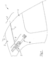
- Fig. 1
- eine Prinzipdarstellung eines Fahrzeug-Teiles in Heckansicht mit einer Scharniervorrichtung zwischen einem vorderen und einem hinteren Dachteil,
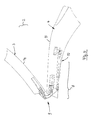
- Fig. 2
- eine teilweise geschnittene Perspektivdarstellung des Fahrzeuges mit zwei jeweils randseitig an den insbesondere einstückigen, stabilen Dachteilen (Hardtop) angeordneten Scharniervorrichtungen,
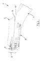
- Fig. 3
- eine teilweise geschnittene Seitenansicht des Verdecks mit den beiden Dachteilen in Schließstellung ähnlich Fig. 1,
- Fig. 4 bis Fig. 6
- jeweilige Bewegungsphasen des vorderen Dachteils bei Betätigung des Scharniervorrichtung,
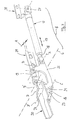
- Fig. 7
- eine vergrößerte Einzeldarstellung der erfindungsgemäßen Scharniervorrichtung in Perspektivdarstellung,
- Fig. 8
- eine Ausschnittsdarstellung der beiden Dachteile mit der Scharniervorrichtung in Draufsicht, und
- Fig. 9 bis Fig. 12
- jeweils vergrößerte Ausschnittsdarstellungen der Scharniervorrichtung in unterschiedlichen Bewegungsphasen (ähnlich Fig. 4 bis 6).
- Fig. 1
- 1 shows a basic illustration of a vehicle part in rear view with a hinge device between a front and a rear roof part,
- Fig. 2
- 3 shows a partially sectioned perspective view of the vehicle with two hinge devices arranged on the edge in each case on the one-piece, stable roof parts (hard top),
- Fig. 3
- 2 shows a partially sectioned side view of the top with the two roof parts in the closed position similar to FIG. 1,
- 4 to 6
- respective phases of movement of the front roof part when the hinge device is actuated,
- Fig. 7
- 3 shows an enlarged individual illustration of the hinge device according to the invention in a perspective illustration,
- Fig. 8
- a sectional view of the two roof parts with the hinge device in plan view, and
- 9 to 12
- each enlarged detail views of the hinge device in different phases of movement (similar to FIGS. 4 to 6).
In Fig. 1 und 2 sind Bauteile eines insgesamt mit 1 bezeichneten
Fahrzeugs dargestellt, dessen Dach 2 als beweglich
mit der Fahrzeugkarosserie verbundene Klappteile ein
vorderes Dachteil 3 und ein hinteres Dachteil 4 aufweist,
wobei diese Dachteile 3, 4 im Bereich einer senkrecht zur
Fahrzeuglängsachse 5 verlaufenden Querachse 6 mit einer
eine Schließ- bzw. Öffnungsstellung (Fig. 3 bzw. Fig. 6)
des Klapp-Daches 2 ermöglichenden Gelenkverbindung
versehen sind. 1 and 2, components of an overall designated 1
Vehicle shown, the
Die erfindungsgemäße Gelenkverbindung zwischen den Dachteilen
3 und 4 ist als eine insgesamt mit 8 bezeichnete
Scharniervorrichtung ausgebildet, deren Schwenkglieder 9
mit zumindest einem steuerbaren Antriebsorgan 10 betätigbar
sind.The joint connection according to the invention between the
Die teilweise geschnittene Perspektivdarstellung gemäß
Fig. 2 verdeutlicht, daß die beiden Dachteile 3 und 4 mit
zwei Scharniervorrichtungen 8, 8' im Bereich der Querachse
6 versehen sind, wobei diese Scharniervorrichtungen
8, 8' als gleiche Baugruppen symmetrisch zur Fahrzeuglängsachse
5 nahe den Seitenrändern 11, 12 des Fahrzeugs 1
angeordnet sind. Ebenso ist denkbar, lediglich nur eine
angetriebene Scharniervorrichtung zwischen den Dachteilen
3, 4 vorzusehen, die beispielsweise im Bereich der
Fahrzeuglängsachse 5 angeordnet sein kann (nicht dargestellt)
oder die Scharniervorrichtungen in einer ebenfalls
nicht dargestellten Ausführungsform mit einem gemeinsamen
Antriebsorgan und nach beiden Seiten hin wirksamen Übertragungsgliedern
zu versehen.The partially cut perspective view according to
Fig. 2 illustrates that the two
In Fig. 3 bis 6 zeigen jeweilige Ausschnittsdarstellungen
des Fahrzeugs 1 die beiden Dachteile 3, 4 in Seitenansichten,
wobei ausgehend von einer Schließstellung gemäß
Fig. 3 jeweilige unterschiedliche Bewegungsphasen beim
Klappvorgang der beiden Dachteile 3, 4 unter Wirkung der
angetriebenen Scharniervorrichtung 8 deutlich werden. In
der Öffnungsstellung gemäß Fig. 6 ist das vordere Dachteil
3 mit seiner Oberseite 14 zur Oberseite 15 des
hinteren Dachteils 4 hin verlagert. Die spezielle konstruktive
Ausbildung der Schwenkglieder 9 an der erfindungsgemäßen
Scharniervorrichtung 8 definiert dabei eine
gesteuerte Kurvenbahn (Pfeil K in Fig. 12) mit einem
Schwenkwinkel S zwischen den beiden Dachteilen 3, 4.
Dieser Schwenkwinkel S kann dabei mehr als 180° betragen
(zusätzlicher Winkel S'), so daß eine Annäherung der Dachteile
3, 4 entsprechend ihrer Profilierung im Bereich der
Oberseiten 14, 15 möglich und eine raumsparende Packlage
erreicht ist.3 to 6 show respective sectional representations
of the
Die vergrößerte Einzeldarstellung gemäß Fig. 7 zeigt die
Scharniervorrichtung 8 mit den Schwenkgliedern 9 in einer
Explosivdarstellung, wobei als Schwenkglieder 9 zwei jeweils
vier Verbindungsachsen A, B, C, D und A', B', C', D'
aufweisende Viergelenke vorgesehen sind, deren Einzelelemente
gemeinsam in der Gelenkverbindungs-Kette wirksam
sind. Die beiden Viergelenke A, B, C, D und A', B', C', D'
sind dabei in zweckmäßiger Ausführung über einen Querlenker
16 verbunden, mit dem die Schubbewegung des Antriebsorgans
10 (Pfeil 17) zwischen den beiden Viergelenken
gekoppelt ist.The enlarged individual representation according to FIG. 7 shows the
Die Prinzipdarstellungen gemäß Fig. 9 bis 12 verdeutlichen,
daß eine Schubstange 18 des in zweckmäßiger Ausführung
als Arbeitszylinder ausgebildeten Antriebsorgans
10 an einer Verbindungsachse A eines Gabellenkers
20 angreift, dessen erster Schenkel 19 am hinteren
Dachteil 4 in der Verbindungsachse B abgestützt ist. Der
Gabellenker 20 weist einen zweiten Schenkel 21 auf, der
endseitig direkt am vorderen Dachteil 3 im Bereich der
Achse D abgestützt ist. Der Gabellenker 20 ist außerdem im
Bereich seines zweiten Schenkels 21 in einer Verbindungsachse
C mit dem zweiten Viergelenk über den Querlenker
16 verbunden. The basic representations according to FIGS. 9 to 12 clarify
that a
Das zweite Viergelenk A', B', C', D' weist einen im mittleren
Bereich des Querlenkers 16 im Bereich der Achse A'
angreifenden sowie am hinteren Dachteil 4 in der Achse B'
abgestützten Bogenschwingteil 23 auf und im Bereich der
Achse C' ist am Querlenker 16 ein mit dem vorderen Dachteil
3 im Bereich der Achse D' verbundener Schwinghebel 24
vorgesehen.The second four-bar linkage A ', B', C ', D' has one in the middle
Area of the
Die Bewegungsphasen-Darstellungen gemäß Fig. 10 bis 12
verdeutlichen unterschiedliche Schwenkstellungen der
Schwenkglieder 9 bzw. der Dachteile 3 und 4, wobei unter
Wirkung der Schwenkvorrichtung 8 das vordere Dachteil 3 im
Bereich eines zum hinteren Dachteil 4 bestehenden Bewegungsspaltes
25 nach Art einer Weitwinkelbewegung die
Kurvenbahn K (Fig. 12) derart durchläuft, daß eine Berührung
von Dachteilen ausgeschlossen ist und über eine
unterschiedliche konstruktive Bemessung der Schwenkglieder
9 insgesamt eine Anpassung an unterschiedliche
Bauteilhöhen H, H' der Dachteil-Konsstruktion möglich ist.The movement phase representations according to FIGS. 10 to 12
illustrate different pivot positions of the
Swivel
Das als Arbeitszylinder ausgebildete Antriebsorgan 10 ist
zylinderseitig über eine ein Gelenkprofilteil 27 (Fig. 7)
aufweisende Halteplatte 28 am Dachteile 4 festgelegt und
die Verbindungsachsen B, B' im Bereich der Schwenkglieder
20 bzw. 23 sind von einer an der Dachteil-Unterseite
verlaufenden Stützstrebe 29 gebildet. Im Bereich des
vorderen Dachteils 3 sind die Verbindungsachsen D, D' an
einer Winkelplatte 30 vorgesehen. Gleichzeitig sind die
Verbindungsgelenke B, B' und D, D' jeweils um ein Abstandsmaß
A (Fig. 7) in Richtung der Querachse 6 versetzt
zueinander angeordnet, so daß die Scharniervorrichtung 8
insgesamt in einen vorteilhaft schmalen Einbauraum montierbar
ist.The
Die vorbeschriebene Scharniervorrichtung 8, 8' ist an
unterschiedliche Einsatzbedingungen über eine entsprechende
Gestaltung ihrer Schwenkglieder 9 und des Antriebsorgans
10 so anpaßbar, daß beispielsweise auch Türen
und Klappen als bewegbare Teile an Baugruppen von
Fahrzeugen, Maschinen, Bauwerken oder dgl. mit dieser angetriebenen
Scharniervorrichtung 8, 8' versehen sein
können.The
Claims (7)
- A vehicle with parts, e.g. doors and panels, adapted for movement towards one another, with a fold-down roof (2) which comprises at least one front roof part (3) and one rear roof part (4) which at least comprise an articulating connection to provide a closed position and an open position, characterised in that the articulating connection is constructed as a hinge device (8, 8') adapted to be directly actuated by a controllable drive member (10).
- A vehicle according to claim 1, characterised in that by means of the driven hinge device(s) (8, 8'), the front roof part (3) can be stowed with its upper surface (14) to the upper surface (15) of the rear roof part (4).
- A vehicle according to claim 1 or 2, characterised in that the hinge device (8, 8') defines between the two roof parts (3, 4) a pivot angle (S) of more than 180°.
- A vehicle according to one of claims 1 to 3, characterised in that the hinge device (8, 8') comprises a plurality of pivotable members (9) defining an articulated chain (A, B, C, D, A', B', C', D') having pivot axes offset in relation to one another.
- A vehicle according to one of claims 1 to 4, characterised in that the hinge device (8, 8') comprises as pivotable members (9) two four-bar joints (A, B, C, D, A', B', C', D') connected via a cross-link (16).
- A vehicle according to one of claims 1 to 5, characterised in that the drive member (10) of the hinge device (8, 8') engages a bifurcated link (20) supported on the rear roof part (4) via a first arm (19) and the second arm (21) of which is at the end supported directly on the front roof part (3) and is furthermore connected to the second four-bar joint (A', B', C', D') via the cross-link (16).
- A vehicle according to one of claims 1 to 6, characterised in that the second four-bar joint (A', B', C',D') is constituted by a curved swinging part (23) engaging the middle portion of the cross-link (16) and supported on the rear roof part (4) and a swinging arm (24) connected to the front roof part (3) and the end of which engages the cross-link (16).
Applications Claiming Priority (2)
| Application Number | Priority Date | Filing Date | Title |
|---|---|---|---|
| DE19623036A DE19623036A1 (en) | 1996-06-08 | 1996-06-08 | Vehicle, in particular with a retractable roof |
| DE19623036 | 1996-06-08 |
Publications (3)
| Publication Number | Publication Date |
|---|---|
| EP0811518A1 EP0811518A1 (en) | 1997-12-10 |
| EP0811518B1 true EP0811518B1 (en) | 2000-02-23 |
| EP0811518B2 EP0811518B2 (en) | 2006-08-23 |
Family
ID=7796483
Family Applications (1)
| Application Number | Title | Priority Date | Filing Date |
|---|---|---|---|
| EP97106765A Expired - Lifetime EP0811518B2 (en) | 1996-06-08 | 1997-04-24 | Vehicle, particularly with foldable roof |
Country Status (3)
| Country | Link |
|---|---|
| US (1) | US5833300A (en) |
| EP (1) | EP0811518B2 (en) |
| DE (2) | DE19623036A1 (en) |
Families Citing this family (40)
| Publication number | Priority date | Publication date | Assignee | Title |
|---|---|---|---|---|
| US6042174A (en) | 1997-08-22 | 2000-03-28 | Asc Incorporated | Latching and control apparatus for an automotive vehicle convertible roof |
| FR2778610B1 (en) * | 1998-05-12 | 2000-08-04 | France Design | FOLDABLE ROOF IN THREE ELEMENTS FOR DISCOVERABLE VEHICLE |
| US6439642B2 (en) * | 1998-05-25 | 2002-08-27 | Dura Convertable Gmbh | Retractable hard top for passenger cars |
| US6269521B1 (en) * | 1998-09-14 | 2001-08-07 | Davis Industries | Three link, plural axes hinge system for upward rotational and translational opening of a closure panel |
| FR2783761B1 (en) * | 1998-09-24 | 2001-06-15 | France Design | RETRACTABLE ROOF FOR TRUCK OR VAN OR BREAK VEHICLE |
| FR2791007B1 (en) * | 1999-03-16 | 2001-05-25 | France Design | FOLDABLE ROOF FOR DISCOVERABLE VEHICLE |
| US6478362B2 (en) * | 1999-12-22 | 2002-11-12 | Ed. Scharwaechter Gmbh | Convertible top and driving device for a convertible top |
| DE10057872B4 (en) * | 2000-11-21 | 2005-02-24 | Cts Fahrzeug-Dachsysteme Gmbh | Hardtop vehicle roof |
| DE10112092C1 (en) * | 2001-03-12 | 2002-08-08 | Cts Fahrzeug Dachsysteme Gmbh | Cabriolet vehicle roof adjustable between a closed position and an open position |
| DE10123228B4 (en) * | 2001-05-12 | 2004-12-23 | Wilhelm Karmann Gmbh | Cabriolet vehicle with at least one flexible roof area |
| DE10123227B4 (en) * | 2001-05-12 | 2005-03-17 | Wilhelm Karmann Gmbh | Convertible vehicle with an at least partially flexible roof |
| JP3524524B2 (en) * | 2001-07-10 | 2004-05-10 | 本田技研工業株式会社 | Convertible hardtop storage structure |
| DE10139354A1 (en) * | 2001-08-17 | 2003-03-13 | Karmann Gmbh W | Convertible car |
| US6767047B2 (en) * | 2002-08-15 | 2004-07-27 | Asc Incorporated | Convertible roof latch |
| US6837535B2 (en) * | 2002-08-15 | 2005-01-04 | Asc Incorporated | Convertible roof system |
| DE20300648U1 (en) | 2003-01-16 | 2004-05-27 | Wilhelm Karmann Gmbh | Motor vehicle with a retractable roof |
| DE102004032809A1 (en) * | 2004-07-07 | 2006-02-16 | Adam Opel Ag | Motor vehicle roof with a roof opening and a folding device for opening and closing the roof opening and a folding device for this and a corresponding motor vehicle |
| DE102004036184A1 (en) * | 2004-07-26 | 2006-02-16 | Eurocopter Deutschland Gmbh | Aircraft door arrangement with a 180 ° swiveling aircraft door |
| DE102004046678B4 (en) * | 2004-09-24 | 2006-08-03 | Cts Fahrzeug-Dachsysteme Gmbh | Movable vehicle roof has first roof part that can be pivoted about vertical joint axis between front position and rear position closer to rear of vehicle |
| DE102005002613A1 (en) | 2005-01-20 | 2006-08-03 | Wilhelm Karmann Gmbh | Hard top hood of a convertible vehicle |
| DE102005033843A1 (en) * | 2005-07-20 | 2007-01-25 | Wilhelm Karmann Gmbh | vehicle |
| DE102005043508B4 (en) * | 2005-09-12 | 2009-11-19 | Magna Car Top Systems Gmbh | Roof for vehicles with open structure |
| US20070094847A1 (en) * | 2005-11-03 | 2007-05-03 | Northrop Grumman Corporation | Combination actuator latch mechanism |
| FR2892979B1 (en) * | 2005-11-09 | 2010-08-27 | Heuliez | RIGID RETRACTABLE MOBILE ROOF |
| DE102005061201B3 (en) * | 2005-12-19 | 2007-04-05 | Rausch & Pausch Gmbh | Convertible system for e.g. cabriolet-vehicle, has support for lever and provided in guiding part, where lever is connected with rear roof part, and connecting strap between guiding body and lever is hinged to lever |
| JP2007238074A (en) * | 2006-02-10 | 2007-09-20 | Aisin Seiki Co Ltd | Vehicular roof automatic opening/closing device |
| DE102006032700B3 (en) * | 2006-07-14 | 2007-11-22 | Webasto Ag | Binding device for a holding device of a lid of an opening vehicle roof comprises an operating lever with a rotating bearing bolt having a receiving unit for a holder on a region facing the inner side of a vehicle |
| US8453298B2 (en) * | 2006-08-18 | 2013-06-04 | Ford Global Technologies | Door hinge system for automotive vehicle |
| DE102006042694B4 (en) * | 2006-09-12 | 2014-05-15 | Webasto Ag | Hardtop folding roof |
| FR2905903B1 (en) * | 2006-09-20 | 2008-12-26 | Heuliez Sa | RETRACTABLE ROOF COMPRISING A FIRST AND A SECOND ROOF ELEMENT, THE FIRST ELEMENT MOVING ABOVE THE SECOND DURING THE MOVEMENT OF THE ROOF |
| DE102007037987B3 (en) * | 2007-08-10 | 2009-01-22 | Magna Steyr Fahrzeugtechnik Ag & Co Kg | Adjustable body unit i.e. roof unit, for connection to body of motor vehicle e.g. car, has adjustment device, where body unit is transferable from closed to open position through combined rotary motions of body unit |
| DE102007045791B4 (en) * | 2007-09-25 | 2022-03-31 | Valmet Automotive Oy | Top module for a convertible vehicle with several fixed roof parts |
| DE102007060487B4 (en) | 2007-12-14 | 2022-08-11 | Magna Car Top Systems Gmbh | Foldable roof for a passenger car |
| DE102009039926B3 (en) * | 2009-09-03 | 2011-03-24 | Webasto-Edscha Cabrio GmbH | Hood arrangement for a convertible vehicle |
| EP3168138B1 (en) * | 2015-11-10 | 2018-06-06 | Airbus Operations GmbH | Aircraft door assembly |
| US11926204B2 (en) * | 2020-03-17 | 2024-03-12 | Richard A. Brown | Hinges for hardtop vehicle covers |
| US11192432B2 (en) | 2020-03-17 | 2021-12-07 | Richard A Brown | Hinge system for hardtop vehicles |
| US11866978B2 (en) * | 2020-12-01 | 2024-01-09 | Questar Gas Company | Door swing control device and associated method |
| US20220258581A1 (en) * | 2021-02-12 | 2022-08-18 | Robert M. Butler | Motor vehicle roof hinge and method for attaching hinge on vehicle roof with removable roof panels |
| CN117508360B (en) * | 2024-01-04 | 2024-03-26 | 南京金龙客车制造有限公司 | Passenger train top flank board flip structure and vehicle |
Family Cites Families (18)
| Publication number | Priority date | Publication date | Assignee | Title |
|---|---|---|---|---|
| US1280357A (en) * | 1914-12-14 | 1918-10-01 | Emil Zuckerman | Hinge. |
| FR733380A (en) † | 1931-06-02 | 1932-10-05 | Auto-displacement retractable hood, for motor vehicles | |
| US2845299A (en) * | 1954-01-20 | 1958-07-29 | Gen Motors Corp | Vehicle top compartment cover mechanism |
| US2812975A (en) † | 1954-06-16 | 1957-11-12 | Warner Heinrich | Convertible hard top for automobiles |
| US3575464A (en) * | 1969-09-29 | 1971-04-20 | Gen Motors Corp | Folding retractable hard top |
| NO147229C (en) * | 1981-02-11 | 1983-03-02 | Kverneland As | DEVICE FOR HANGING, SPECIAL FOR AGRICULTURAL EQUIPMENT |
| US4510714A (en) * | 1982-09-30 | 1985-04-16 | The Boeing Company | Powered outward-opening cargo door |
| DE3519203A1 (en) * | 1985-01-19 | 1986-07-24 | Dr.Ing.H.C. F. Porsche Ag, 7000 Stuttgart | ACTUATING DEVICE FOR A DOOR OF A MOTOR VEHICLE |
| JPS6390432A (en) * | 1986-10-02 | 1988-04-21 | Mazda Motor Corp | Structure of upper car body of automobile |
| DE3635373A1 (en) * | 1986-10-17 | 1988-04-21 | Autoschmiede Meier Menge Gmbh | Folding roof for motor vehicles |
| DE3808909C1 (en) † | 1988-03-17 | 1989-04-20 | Bayerische Motoren Werke Ag, 8000 Muenchen, De | |
| DE3903358A1 (en) * | 1989-02-04 | 1990-08-30 | Bayerische Motoren Werke Ag | Retractable vehicle roof |
| US5033789A (en) † | 1989-03-31 | 1991-07-23 | Aisin Seiki Kabushiki Kaisha | Convertible car body structure |
| US5080428A (en) * | 1989-12-27 | 1992-01-14 | Rouland Paul K | Foldable roof assembly for vehicles having a TARGA top |
| FI89571C (en) † | 1992-03-05 | 1993-10-25 | Saab Valmet Ab Oy | Open car roof opening mechanism |
| DE4320468C1 (en) † | 1993-06-21 | 1994-10-20 | Daimler Benz Ag | Motor vehicle with a lowerable roof construction |
| US5490709A (en) * | 1993-12-07 | 1996-02-13 | Asc Incorporated | Hinge for a folding roof in a convertible automotive vehicle |
| EP0700802A1 (en) * | 1994-09-09 | 1996-03-13 | Caterpillar Inc. | Articulated cover for a top loading hauling body |
-
1996
- 1996-06-08 DE DE19623036A patent/DE19623036A1/en not_active Withdrawn
-
1997
- 1997-04-24 DE DE59701143T patent/DE59701143D1/en not_active Expired - Lifetime
- 1997-04-24 EP EP97106765A patent/EP0811518B2/en not_active Expired - Lifetime
- 1997-05-27 US US08/863,701 patent/US5833300A/en not_active Expired - Lifetime
Also Published As
| Publication number | Publication date |
|---|---|
| EP0811518B2 (en) | 2006-08-23 |
| US5833300A (en) | 1998-11-10 |
| EP0811518A1 (en) | 1997-12-10 |
| DE59701143D1 (en) | 2000-03-30 |
| DE19623036A1 (en) | 1997-12-11 |
Similar Documents
| Publication | Publication Date | Title |
|---|---|---|
| EP0811518B1 (en) | Vehicle, particularly with foldable roof | |
| EP0844125B1 (en) | Convertible vehicle. | |
| EP1112879B1 (en) | Convertible vehicle roof | |
| DE10063152B4 (en) | Folding roof cars | |
| EP0826537B1 (en) | Vehicle roof construction,especially for passenger motor vehicle | |
| DE4445580C1 (en) | Hard=top vehicle roof linkage | |
| DE4446483C2 (en) | Hardtop vehicle | |
| EP0835779B1 (en) | Retractable roof for vehicle | |
| EP0760301B1 (en) | Foldable top for convertible vehicle | |
| EP0832774B1 (en) | Roof structure for convertible vehicle | |
| DE19755254A1 (en) | Motor vehicle with a retractable roof structure | |
| DE4316485A1 (en) | Folding top for motor vehicles | |
| EP1080966A2 (en) | Foldable top for convertible | |
| EP1831043B1 (en) | Cabriolet vehicle having a movable rear-window shelf | |
| DE10107077B4 (en) | Convertible vehicle roof of a convertible | |
| DE10144583A1 (en) | Convertible top for a convertible vehicle | |
| DE19939954B4 (en) | Faltschiebedachanordnung | |
| WO2003029037A1 (en) | Multiple-part removable hard top for motor vehicle | |
| WO2005047037A1 (en) | Vehicle, particularly a passenger vehicle, with openings in the superstructure thereof | |
| DE10245361B4 (en) | Convertible vehicle with retractable folding top | |
| EP1157871B2 (en) | Convertible vehicle | |
| EP0806312B1 (en) | Foldable top for convertible vehicle | |
| DE19942429B4 (en) | Quarter turn actuator for a front side roof bar of a vehicle roof or convertible top | |
| DE102004023056A1 (en) | Collapsible roof for motor vehicle, has roof part and rear part that is pivoted through motor adjustment unit around real or virtual stationary or portable transverse axis at coupling unit | |
| DE19932501C2 (en) | Mechanism for a swiveling tailgate |
Legal Events
| Date | Code | Title | Description |
|---|---|---|---|
| PUAI | Public reference made under article 153(3) epc to a published international application that has entered the european phase |
Free format text: ORIGINAL CODE: 0009012 |
|
| AK | Designated contracting states |
Kind code of ref document: A1 Designated state(s): DE FI FR GB IT SE |
|
| 17P | Request for examination filed |
Effective date: 19971216 |
|
| GRAG | Despatch of communication of intention to grant |
Free format text: ORIGINAL CODE: EPIDOS AGRA |
|
| 17Q | First examination report despatched |
Effective date: 19990625 |
|
| GRAG | Despatch of communication of intention to grant |
Free format text: ORIGINAL CODE: EPIDOS AGRA |
|
| GRAH | Despatch of communication of intention to grant a patent |
Free format text: ORIGINAL CODE: EPIDOS IGRA |
|
| GRAH | Despatch of communication of intention to grant a patent |
Free format text: ORIGINAL CODE: EPIDOS IGRA |
|
| GRAA | (expected) grant |
Free format text: ORIGINAL CODE: 0009210 |
|
| AK | Designated contracting states |
Kind code of ref document: B1 Designated state(s): DE FI FR GB IT SE |
|
| ITF | It: translation for a ep patent filed |
Owner name: BARZANO' E ZANARDO MILANO S.P.A. |
|
| REF | Corresponds to: |
Ref document number: 59701143 Country of ref document: DE Date of ref document: 20000330 |
|
| GBT | Gb: translation of ep patent filed (gb section 77(6)(a)/1977) |
Effective date: 20000320 |
|
| ET | Fr: translation filed | ||
| PLBQ | Unpublished change to opponent data |
Free format text: ORIGINAL CODE: EPIDOS OPPO |
|
| PLBI | Opposition filed |
Free format text: ORIGINAL CODE: 0009260 |
|
| PLBF | Reply of patent proprietor to notice(s) of opposition |
Free format text: ORIGINAL CODE: EPIDOS OBSO |
|
| 26 | Opposition filed |
Opponent name: PEUGEOT CITROEN AUTOMOBILES Effective date: 20001113 |
|
| PGFP | Annual fee paid to national office [announced via postgrant information from national office to epo] |
Ref country code: SE Payment date: 20010411 Year of fee payment: 5 Ref country code: FI Payment date: 20010411 Year of fee payment: 5 |
|
| PLBF | Reply of patent proprietor to notice(s) of opposition |
Free format text: ORIGINAL CODE: EPIDOS OBSO |
|
| REG | Reference to a national code |
Ref country code: GB Ref legal event code: IF02 |
|
| RDAH | Patent revoked |
Free format text: ORIGINAL CODE: EPIDOS REVO |
|
| PG25 | Lapsed in a contracting state [announced via postgrant information from national office to epo] |
Ref country code: FI Free format text: LAPSE BECAUSE OF NON-PAYMENT OF DUE FEES Effective date: 20020424 |
|
| PG25 | Lapsed in a contracting state [announced via postgrant information from national office to epo] |
Ref country code: SE Free format text: LAPSE BECAUSE OF NON-PAYMENT OF DUE FEES Effective date: 20020425 |
|
| APAC | Appeal dossier modified |
Free format text: ORIGINAL CODE: EPIDOS NOAPO |
|
| APAC | Appeal dossier modified |
Free format text: ORIGINAL CODE: EPIDOS NOAPO |
|
| EUG | Se: european patent has lapsed |
Ref document number: 97106765.7 |
|
| APBU | Appeal procedure closed |
Free format text: ORIGINAL CODE: EPIDOSNNOA9O |
|
| APAA | Appeal reference recorded |
Free format text: ORIGINAL CODE: EPIDOS REFN |
|
| APAH | Appeal reference modified |
Free format text: ORIGINAL CODE: EPIDOSCREFNO |
|
| PUAH | Patent maintained in amended form |
Free format text: ORIGINAL CODE: 0009272 |
|
| STAA | Information on the status of an ep patent application or granted ep patent |
Free format text: STATUS: PATENT MAINTAINED AS AMENDED |
|
| 27A | Patent maintained in amended form |
Effective date: 20060823 |
|
| AK | Designated contracting states |
Kind code of ref document: B2 Designated state(s): DE FI FR GB IT SE |
|
| GBTA | Gb: translation of amended ep patent filed (gb section 77(6)(b)/1977) | ||
| ET3 | Fr: translation filed ** decision concerning opposition | ||
| PGFP | Annual fee paid to national office [announced via postgrant information from national office to epo] |
Ref country code: GB Payment date: 20070418 Year of fee payment: 11 |
|
| PGFP | Annual fee paid to national office [announced via postgrant information from national office to epo] |
Ref country code: IT Payment date: 20070521 Year of fee payment: 11 |
|
| PGFP | Annual fee paid to national office [announced via postgrant information from national office to epo] |
Ref country code: FR Payment date: 20070411 Year of fee payment: 11 |
|
| GBPC | Gb: european patent ceased through non-payment of renewal fee |
Effective date: 20080424 |
|
| REG | Reference to a national code |
Ref country code: FR Ref legal event code: ST Effective date: 20081231 |
|
| PG25 | Lapsed in a contracting state [announced via postgrant information from national office to epo] |
Ref country code: FR Free format text: LAPSE BECAUSE OF NON-PAYMENT OF DUE FEES Effective date: 20080430 |
|
| PG25 | Lapsed in a contracting state [announced via postgrant information from national office to epo] |
Ref country code: GB Free format text: LAPSE BECAUSE OF NON-PAYMENT OF DUE FEES Effective date: 20080424 |
|
| PG25 | Lapsed in a contracting state [announced via postgrant information from national office to epo] |
Ref country code: IT Free format text: LAPSE BECAUSE OF NON-PAYMENT OF DUE FEES Effective date: 20080424 |
|
| REG | Reference to a national code |
Ref country code: DE Ref legal event code: R082 Ref document number: 59701143 Country of ref document: DE Representative=s name: KRONTHALER, SCHMIDT & COLL. PATENTANWALTSKANZL, DE Effective date: 20131128 Ref country code: DE Ref legal event code: R081 Ref document number: 59701143 Country of ref document: DE Owner name: BAYERISCHE MOTOREN WERKE AKTIENGESELLSCHAFT, DE Free format text: FORMER OWNERS: WILHELM KARMANN GMBH, 49084 OSNABRUECK, DE; BAYERISCHE MOTOREN WERKE AKTIENGESELLSCHAFT, 80809 MUENCHEN, DE Effective date: 20131128 Ref country code: DE Ref legal event code: R081 Ref document number: 59701143 Country of ref document: DE Owner name: VALMET AUTOMOTIVE OY, FI Free format text: FORMER OWNERS: WILHELM KARMANN GMBH, 49084 OSNABRUECK, DE; BAYERISCHE MOTOREN WERKE AKTIENGESELLSCHAFT, 80809 MUENCHEN, DE Effective date: 20131128 Ref country code: DE Ref legal event code: R081 Ref document number: 59701143 Country of ref document: DE Owner name: VALMET AUTOMOTIVE OY, FI Free format text: FORMER OWNER: WILHELM KARMANN GMBH, BAYERISCHE MOTOREN WERKE AKTIEN, , DE Effective date: 20131128 Ref country code: DE Ref legal event code: R081 Ref document number: 59701143 Country of ref document: DE Owner name: BAYERISCHE MOTOREN WERKE AKTIENGESELLSCHAFT, DE Free format text: FORMER OWNER: WILHELM KARMANN GMBH, BAYERISCHE MOTOREN WERKE AKTIEN, , DE Effective date: 20131128 |
|
| PGFP | Annual fee paid to national office [announced via postgrant information from national office to epo] |
Ref country code: DE Payment date: 20140521 Year of fee payment: 18 |
|
| REG | Reference to a national code |
Ref country code: DE Ref legal event code: R119 Ref document number: 59701143 Country of ref document: DE |
|
| PG25 | Lapsed in a contracting state [announced via postgrant information from national office to epo] |
Ref country code: DE Free format text: LAPSE BECAUSE OF NON-PAYMENT OF DUE FEES Effective date: 20151103 |