EP0826537B1 - Vehicle roof construction,especially for passenger motor vehicle - Google Patents
Vehicle roof construction,especially for passenger motor vehicle Download PDFInfo
- Publication number
- EP0826537B1 EP0826537B1 EP97113939A EP97113939A EP0826537B1 EP 0826537 B1 EP0826537 B1 EP 0826537B1 EP 97113939 A EP97113939 A EP 97113939A EP 97113939 A EP97113939 A EP 97113939A EP 0826537 B1 EP0826537 B1 EP 0826537B1
- Authority
- EP
- European Patent Office
- Prior art keywords
- roof
- vehicle
- roof construction
- construction according
- roof part
- Prior art date
- Legal status (The legal status is an assumption and is not a legal conclusion. Google has not performed a legal analysis and makes no representation as to the accuracy of the status listed.)
- Expired - Lifetime
Links
Images

Classifications
-
- B—PERFORMING OPERATIONS; TRANSPORTING
- B60—VEHICLES IN GENERAL
- B60J—WINDOWS, WINDSCREENS, NON-FIXED ROOFS, DOORS, OR SIMILAR DEVICES FOR VEHICLES; REMOVABLE EXTERNAL PROTECTIVE COVERINGS SPECIALLY ADAPTED FOR VEHICLES
- B60J1/00—Windows; Windscreens; Accessories therefor
- B60J1/18—Windows; Windscreens; Accessories therefor arranged at the vehicle rear
- B60J1/1807—Windows; Windscreens; Accessories therefor arranged at the vehicle rear movable for vehicles with convertible top
- B60J1/1823—Windows; Windscreens; Accessories therefor arranged at the vehicle rear movable for vehicles with convertible top adjustable relative to hard- or soft-top, e.g. pivotable
-
- B—PERFORMING OPERATIONS; TRANSPORTING
- B60—VEHICLES IN GENERAL
- B60J—WINDOWS, WINDSCREENS, NON-FIXED ROOFS, DOORS, OR SIMILAR DEVICES FOR VEHICLES; REMOVABLE EXTERNAL PROTECTIVE COVERINGS SPECIALLY ADAPTED FOR VEHICLES
- B60J7/00—Non-fixed roofs; Roofs with movable panels, e.g. rotary sunroofs
- B60J7/08—Non-fixed roofs; Roofs with movable panels, e.g. rotary sunroofs of non-sliding type, i.e. movable or removable roofs or panels, e.g. let-down tops or roofs capable of being easily detached or of assuming a collapsed or inoperative position
- B60J7/12—Non-fixed roofs; Roofs with movable panels, e.g. rotary sunroofs of non-sliding type, i.e. movable or removable roofs or panels, e.g. let-down tops or roofs capable of being easily detached or of assuming a collapsed or inoperative position foldable; Tensioning mechanisms therefor, e.g. struts
- B60J7/14—Non-fixed roofs; Roofs with movable panels, e.g. rotary sunroofs of non-sliding type, i.e. movable or removable roofs or panels, e.g. let-down tops or roofs capable of being easily detached or of assuming a collapsed or inoperative position foldable; Tensioning mechanisms therefor, e.g. struts with a plurality of rigid plate-like elements or rigid non plate-like elements, e.g. with non-slidable, but pivotable or foldable movement
- B60J7/143—Non-fixed roofs; Roofs with movable panels, e.g. rotary sunroofs of non-sliding type, i.e. movable or removable roofs or panels, e.g. let-down tops or roofs capable of being easily detached or of assuming a collapsed or inoperative position foldable; Tensioning mechanisms therefor, e.g. struts with a plurality of rigid plate-like elements or rigid non plate-like elements, e.g. with non-slidable, but pivotable or foldable movement for covering the passenger compartment
- B60J7/145—Non-fixed roofs; Roofs with movable panels, e.g. rotary sunroofs of non-sliding type, i.e. movable or removable roofs or panels, e.g. let-down tops or roofs capable of being easily detached or of assuming a collapsed or inoperative position foldable; Tensioning mechanisms therefor, e.g. struts with a plurality of rigid plate-like elements or rigid non plate-like elements, e.g. with non-slidable, but pivotable or foldable movement for covering the passenger compartment at least two elements being folded in clamp-shell fashion
Definitions
- the invention relates to a roof structure for a Motor vehicle, in particular for a passenger car, with one in a closed functional position on a windbreak frame the vehicle body, dimensionally stable front roof part, as well as with a forming the C-pillar sections and with a rear window provided dimensionally stable rear Roof part that is pivotally connected and by means of a control mechanism between a lowered rest position and a closed functional position are, with the rear roof part in its lowered rest position is pivoted about a horizontal transverse axis such that the rear ends of the C-pillar sections - on the vehicle's longitudinal direction related - projecting forward, whereby the C-pillar sections at least in the lowered rest position and at least part of their length - from hers starting at the rear ends - protrude freely without cross-connection.
- the roof structure for a convertible has a front one Roof part and a rear roof part, both of which are dimensionally stable are designed.
- the two roof parts can be folded together and in a sunken resting position behind the front seats of the vehicle interior can be lowered.
- the rear roof section has C-pillar sections on that in the lowered rest position Part of their length without cross-connection and with flank the front roof part laterally along these lengths.
- the roof structure has a front, dimensionally stable Roof shell on that in the closed working position locked to a windshield cross member of the vehicle body is. In the longitudinal direction of the vehicle, it closes at the front Roof part a rear roof part in the form of a dimensionally stable Roof shell on, which can be pivoted with the front roof shell connected is.
- the rear roof shell has two rear windows laterally flanking C-pillar sections.
- the rear roof shell In the field of the lower ends of the C-pillar sections is the rear roof shell around a vehicle-fixed and transverse to the longitudinal direction of the vehicle Pivot axis so pivotally mounted that the rear roof part in a lowered rest position in one Storage space of the motor vehicle is stored that the C-pillar sections protrude from the rear roof shell to the front.
- the storage space is located in a rear area of the vehicle body. For stowing transport items remains with lowered Roof construction only an extremely small residual space.
- the object of the invention is a roof structure of the beginning mentioned type to create an enlarged storage space in provides a rear area of the motor vehicle.
- control means for advance of the rear roof part in the vehicle longitudinal direction are provided that the C-pillar sections in the rest position at least partially a rear area of the vehicle interior flank to the side.
- the invention is that the rear window between the C-pillar sections is arranged such that at least in the in the lowered rest position, the C-pillar sections over a part protrude their length freely.
- This feature of the invention can be achieved either by being a relatively short and opposite the rear window is recessed at the ends of the C-pillar sections is provided, or in that the rear window is detachably arranged on the rear roof part and for the lowered Rest position in a simple manner from the rear roof part is separated.
- a cross connection serving in the area of the lower ends of the C-pillar sections
- Rear window separable to the C-pillar sections on the rear Roof part arranged.
- the rear window can be articulated the rear roof part and be stored together with the roof structure Can be stored in the rear area of the vehicle body be, the rear window in the stored rest position occupies the C-pillar section releasing position.
- the rear window can be removed from the rear roof section and separately stowed in the vehicle for the roof structure.
- the rear window is at least partially set back in relation to the C-pillar sections arranged on the rear roof part that the C-pillar sections protrude freely over part of their length.
- closed sports car Frazier
- the rear roof part of the present is analogous Passenger car designed by the C-pillar sections over the steeply aligned rear window - on the closed Functional position related - pulled further back.
- these are front and rear roof section using an upper parallelogram linkage can be lowered from its closed functional position, and the two lower bearing points of the upper parallelogram linkage are part of a body-supported, lower guide arrangement serving as control means.
- the lower bearing points are used as the basis the person responsible for the lowering movement of the two roof parts Parallelogram linkage in a simple way to the front shift, which also causes the roof structure in the lowered Rest position is shifted forward.
- the lower one Guide arrangement designed as a parallelogram linkage. This is a particularly simple solution to advance to achieve the roof parts.
- the upper and the lower parallelogram linkage on both sides of the roof parts provided with identical rod parts, those for the equation synchronization means assigned to their movement processes are. This ensures particularly good functional reliability the parallelogram linkage guaranteed.
- positive guidance means between the upper and lower parallelogram linkages for synchronous superimposition of the movements of the two parallelogram linkages intended. This is the time for a lowering process or reduced a lifting process of the roof structure, because lowering and advancing the roof structure can be done simultaneously.
- a positive guidance means one that attacks on the rear roof part and is fixed to the vehicle mounted pivot lever arrangement provided.
- the mechanical simple design allows long and maintenance-free functional reliability.
- a corresponding traction drive in the form of a chain or a belt drive is provided, which a tensioning device must be assigned to compensate for elongations of the traction means.
- the pivot lever arrangement as a drive part for the opening and closing movement one closing a storage space for the roof structure Cover flap provided.
- the pivot lever arrangement a dual function by both controlling the cover flap as well as to synchronize the movements of the two Parallelogram linkage is used. This allows the pivot lever assembly via appropriate kinematics or directly with be connected to the cover flap.
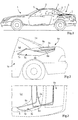
- FIG. 1 shows a passenger car 1 from a driver's area and a rear area 4 composed vehicle interior on that forward through a windshield, two side A-pillars of the vehicle body and one of the two Connect the A-pillars above the windshield Wind protection cross member 5 is limited.
- Up and back is the vehicle interior by a front roof part 2 and a rear roof part 3 bounded between the vehicle interior closing functional position and one in one Rear area 6 of the passenger car in the lowered rest position are mobile.
- Both the roof part 2 and the roof part 3 are shell-like dimensionally stable from a corresponding plastic material or made of pressed metal parts.
- the front one Roof part 2 connects to the windshield cross member 5 and is in the closed functional position by means of a lock committed to this.
- the front roof part 2 extends in Longitudinal vehicle direction to the rear up to about the level of the transition the driver - in the rear area of the vehicle interior.
- the rear roof part 3 which by means of a hinge arrangement around a horizontal and transverse to the vehicle longitudinal direction extending pivot axis 12 on the front roof part 2 is pivotally mounted.
- the roof part 3 has a flush to the front roof part 2 adjoining roof area, which to both sides merges into C-pillar sections 7, which extend up to a vehicle curb of the vehicle body downward.
- the rear roof part 3 pivotally connected front roof part 2 by means of Control mechanism through a parallel shift also in the rear area 6 lowered, the front roof part 2 like a folding knife is placed on the rear roof part 3.
- the rear Roof part 3 is such in its lowered rest position aligned that the abutting edge to the front roof part 2 after rear and the C-pillar sections 3 in the vehicle longitudinal direction protrude forward.
- the rear window 8a can a suitable control mechanism articulated with the front Roof part 2a connected and during the lowering process from the Receiving section 8b of the rear roof part 3a released and in the position shown in Fig. 2 are stored. It is also possible the rear window 8a without a connection to the front Roof part 2a only detachably in the receiving section 8b of the to hold rear roof part 3a and the rear window 8a lowering the roof structure from the rear roof part 3a to remove. After lowering the roof structure (parts 2a and 3a) can then the rear window 8a separately in the storage space of the Stored rear area 6a and in particular according to FIGS. 2 and 3 be positioned.
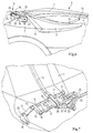
- the other parallelogram lever of the parallelogram linkage 10 is by an S-like curved lever rod 14th formed at its lower pivot point on a connecting lever 24 about a hinge axis 15 and at an upper hinge point 13 with the front roof part 2 in a manner not shown is pivotally connected.
- the connecting lever 24 is in turn Part of a lower parallelogram linkage 11, the Functional sections are shown in dashed lines.
- the lower Parallelogram linkage 11 is in the area of its lower hinge points, i.e. in the area of its base, stored on the body, so that the upper parallelogram linkage 10 over the lower parallelogram linkage 11 is in turn mounted on the body.
- the parallelogram linkage 11 is one by one Body-fixed pivot axis 23 pivoting parallelogram lever 20 and the other by a parallel one further body-fixed pivot axis 22 pivotally mounted Parallelogram lever 21 formed.
- the parallelogram linkage 11 is the displacement of the folded Roof construction in the longitudinal direction of the vehicle, namely for the lowered rest position in the vehicle's longitudinal direction to the front and to raise it again to the closed functional position back again in the longitudinal direction of the vehicle.
- the parallelogram lever according to Fig. 7 designed in pairs. At the However, this does not change the function described. To the shown in Fig. 7 left part of the control mechanism with the identically designed one.
- the pivot axis 23 with one with the same reference number provided synchronization shaft equipped, which is horizontal across the vehicle width extends to the opposite parallelogram lever 20.
- the Initiation of the driving force in the serving as a drive lever Parallelogram lever 20 can be done via the synchronization shaft.
- a traction mechanism drive which serves as a transmission means are the two parallelogram linkages 10 and 11 together coupled that their respective movements overlap.
- the traction mechanism drive in the illustrated embodiment is designed as a belt drive, has one to the pivot axis 23 coaxial disc 19 held on the body, on the outer circumference a circumferential belt 25 at one Rolling movement of the parallelogram lever 20 rolls.
- the other Run of the belt 25 encloses a disc wheel that rotates with the axis of rotation 16 is connected.
- a predetermined gear ratio is defined.
- a second belt drive 26 is provided, on the one hand one coaxial with the small disc wheel of the first belt drive and rotatably arranged with it on the axis of rotation 16 Disc wheel and on the other hand on one on the lever rod 14 fixed disc wheel rolls. This will make the lever rod 14 by applying a torque in addition to the longitudinal force of the lever supports, causing the upper parallelogram linkage especially in the area of its end positions where it is close is a dead center position, is moved safely without there is a risk of blocking.
- the second belt drive 26 has a gear ratio of at least 1: 1, where the gear ratio depends on whether via the belt drive a torsional bias is applied to the lever rod 14 to be or not. This will make it easier to swing out of the front roof part 2 from the near dead center positions achieved.
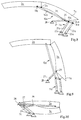
- the roof structure according to the embodiment of FIGS. 8 to 10 also has a front roof part 2a and a rear one Roof part 3a, which is provided with rear C-pillar sections 7a is.
- This roof construction is also an upper parallelogram linkage 10a and a lower parallelogram linkage 11a for Collapse the roof structure and advance the Roof structure assigned, with both the upper parallelogram linkage 10a and the lower parallelogram linkage 11a the parallelogram linkage of the embodiment according to the 4 to 7 correspond.
- the pivot lever assembly 27 is used in a manner not shown in addition to the forced opening and closing of a cover flap the vehicle body, which is the storage space for the The roof construction closes. Through the up and down movement the swivel lever arrangement 27 can briefly cover the flap be opened while the lower parallelogram linkage 11a turns forward.
Description
Die Erfindung bezieht sich auf eine Dachkonstruktion für ein Kraftfahrzeug, insbesondere für einen Personenkraftwagen, mit einem in einer geschlossenen Funktionsposition an einen Windschutzrahmen der Fahrzeugkarosserie anschließenden, formstabilen vorderen Dachteil, sowie mit einem die C-Säulenabschnitte bildenden und mit einer Heckscheibe versehenen formstabilen hinteren Dachteil, die schwenkbeweglich miteinander verbunden und mittels eines Steuermechanismus zwischen einer abgesenkten Ruheposition und einer geschlossenen Funktionsposition beweglich sind, wobei das hintere Dachteil in seiner abgesenkten Ruheposition derart um eine horizontale Querachse verschwenkt ist, daß die hinteren Enden der C-Säulenabschnitte - auf die Fahrzeuglängsrichtung bezogen - nach vorne ragend ausgerichtet sind, wobei die C-Säulenabschnitte zumindest in der abgesenkten Ruheposition und zumindest über einen Teil ihrer Länge - von ihren hinteren Enden ausgehend - ohne Querverbindung frei abragen.The invention relates to a roof structure for a Motor vehicle, in particular for a passenger car, with one in a closed functional position on a windbreak frame the vehicle body, dimensionally stable front roof part, as well as with a forming the C-pillar sections and with a rear window provided dimensionally stable rear Roof part that is pivotally connected and by means of a control mechanism between a lowered rest position and a closed functional position are, with the rear roof part in its lowered rest position is pivoted about a horizontal transverse axis such that the rear ends of the C-pillar sections - on the vehicle's longitudinal direction related - projecting forward, whereby the C-pillar sections at least in the lowered rest position and at least part of their length - from hers starting at the rear ends - protrude freely without cross-connection.
Eine solche Dachkonstruktion ist aus dem US-Patent 5 490 709 bekannt. Die Dachkonstruktion für ein Cabriolet weist einen vorderen Dachteil sowie einen hinteren Dachteil auf, die beide formstabil gestaltet sind. Die beiden Dachteile sind zusammenklappbar und in eine versenkte Ruheposition hinter den Vordersitzen des Fahrzeuginnenraumes absenkbar. Der hintere Dachteil weist C-Säulenabschnitte auf, die in der abgesenkten Ruheposition über einen Teil ihrer Länge ohne Querverbindung frei abragen und mit diesen Längenabschnitten den vorderen Dachteil seitlich flankieren.Such a roof structure is known from US Pat. No. 5,490,709. The roof structure for a convertible has a front one Roof part and a rear roof part, both of which are dimensionally stable are designed. The two roof parts can be folded together and in a sunken resting position behind the front seats of the vehicle interior can be lowered. The rear roof section has C-pillar sections on that in the lowered rest position Part of their length without cross-connection and with flank the front roof part laterally along these lengths.
Eine weitere Dachkonstruktion ist bei Mercedes-Benz SLK-Roadstern bekannt. Die Dachkonstruktion weist eine vordere, formstabile Dachschale auf, die in der geschlossenen Funktionsposition an einem Windschutzquerträger der Fahrzeugkarosserie verriegelt ist. In Fahrzeuglängsrichtung nach hinten schließt an den vorderen Dachteil ein hinterer Dachteil in Form einer formstabilen Dachschale an, die schwenkbeweglich mit der vorderen Dachschale verbunden ist. Die hintere Dachschale weist zwei eine Heckscheibe seitlich flankierende C-Säulenabschnitte auf. Im Bereich der unteren Enden der C-Säulenabschnitte ist die hintere Dachschale um eine fahrzeugfeste und quer zur Fahrzeuglängsrichtung verlaufende Schwenkachse derart schwenkbeweglich gelagert, daß das hintere Dachteil in einer abgesenkten Ruheposition derart in einem Stauraum des Kraftfahrzeugs abgelegt ist, daß die C-Säulenabschnitte der hinteren Dachschale nach vorne abragen. Der Stauraum befindet sich in einem Heckbereich der Fahrzeugkarosserie. Für das Verstauen von Transportgegenständen verbleibt bei abgesenkter Dachkonstruktion lediglich ein äußerst geringer Restraum.Another roof construction is at Mercedes-Benz SLK roadsters known. The roof structure has a front, dimensionally stable Roof shell on that in the closed working position locked to a windshield cross member of the vehicle body is. In the longitudinal direction of the vehicle, it closes at the front Roof part a rear roof part in the form of a dimensionally stable Roof shell on, which can be pivoted with the front roof shell connected is. The rear roof shell has two rear windows laterally flanking C-pillar sections. In the field of the lower ends of the C-pillar sections is the rear roof shell around a vehicle-fixed and transverse to the longitudinal direction of the vehicle Pivot axis so pivotally mounted that the rear roof part in a lowered rest position in one Storage space of the motor vehicle is stored that the C-pillar sections protrude from the rear roof shell to the front. The storage space is located in a rear area of the vehicle body. For stowing transport items remains with lowered Roof construction only an extremely small residual space.
Aufgabe der Erfindung ist es, eine Dachkonstruktion der eingangs genannten Art zu schaffen, die einen vergrößerten Stauraum in einem Heckbereich des Kraftfahrzeugs zur Verfügung stellt.The object of the invention is a roof structure of the beginning mentioned type to create an enlarged storage space in provides a rear area of the motor vehicle.
Diese Aufgabe wird dadurch gelöst, daß Steuerungsmittel zum Vorverlagern des hinteren Dachteiles in Fahrzeuglängsrichtung derart vorgesehen sind, daß die C-Säulenabschnitte in der Ruheposition zumindest teilweise einen Fondbereich des Fahrzeuginnenraumes seitlich flankieren. This object is achieved in that control means for advance of the rear roof part in the vehicle longitudinal direction are provided that the C-pillar sections in the rest position at least partially a rear area of the vehicle interior flank to the side.
Dadurch wird das hintere Dachteil, an dem das vordere Dachteil angelenkt ist, entweder während des Absenkvorganges oder nach dem Absenken in den Stauraum zusätzlich um einen bestimmten Betrag nach vorne verlagert, so daß im Heckbereich des Personenkraftwagens ein um den nach vorne verlagerten Weg der Dachkonstruktion vergrößerter Stauraum zur Verfügung steht. Vorteilhaft wird dazu der zu beiden Seiten neben dem Fondbereich des Fahrzeuginnenraumes innerhalb der Fahrzeugkarosserie zur Verfügung stehende Raum verwendet. Bei einem offenen Personenkraftwagen ist häufig ein solcher Raum naturgemäß bereits durch einen in der Draufsicht U-förmigen Verdeckkasten vorhanden. Zwischen dem seitlichen Abschluß des Fondbereiches des Fahrzeuginnenraumes sowie der Außenhaut der Fahrzeugkarosserie ist somit üblicherweise ein ausreichender Raum vorhanden, um die C-Säulenabschnitte des hinteren Dachteiles und damit die gesamte Dachkonstruktion nach vorne verlagern zu können. Voraussetzung dafür ist erfindungsgemäß jedoch, daß die Heckscheibe zwischen den C-Säulenabschnitten derart angeordnet ist, daß zumindest in der abgesenkten Ruheposition die C-Säulenabschnitte über einen Teil ihrer Länge frei abragen. Dieses erfindungsgemäße Merkmal kann entweder dadurch erzielt werden, daß eine relativ kurze und gegenüber den Enden der C-Säulenabschnitte zurückspringende Heckscheibe vorgesehen ist, oder aber dadurch, daß die Heckscheibe lösbar an dem hinteren Dachteil angeordnet ist und für die abgesenkte Ruheposition in einfacher Weise von dem hinteren Dachteil getrennt wird. In gleicher Weise ist es auch möglich, die Heckscheibe über ihre Länge zweiteilig auszubilden und lediglich den zwischen den hinteren Enden der C-Säulenabschnitte befindlichen Teil beim Absenken in die Ruheposition zu entfernen oder zu verlagern.This will attach the rear roof panel to the front roof panel is articulated, either during the lowering process or after lowering into the storage space by a certain amount shifted forward so that in the rear area of the passenger car a way of moving the roof structure forward enlarged storage space is available. Advantageous for this purpose is the on both sides next to the rear area of the vehicle interior available within the vehicle body standing space used. With an open passenger car Often such a room is naturally already in one the top view U-shaped convertible top compartment available. Between the side closure of the rear area of the vehicle interior and the outer skin of the vehicle body is therefore common there is sufficient space around the C-pillar sections of the rear roof part and thus the entire roof structure to be able to move forward. Prerequisite for this However, the invention is that the rear window between the C-pillar sections is arranged such that at least in the in the lowered rest position, the C-pillar sections over a part protrude their length freely. This feature of the invention can can be achieved either by being a relatively short and opposite the rear window is recessed at the ends of the C-pillar sections is provided, or in that the rear window is detachably arranged on the rear roof part and for the lowered Rest position in a simple manner from the rear roof part is separated. In the same way, it is also possible to use the rear window train in two parts over their length and only the located between the rear ends of the C-pillar sections Remove or relocate part when lowering to the rest position.
Weitere Vorteile und Merkmale der Erfindung ergeben sich aus den Unteransprüchen.Further advantages and features of the invention result from the Dependent claims.
In erster Ausgestaltung der Erfindung ist eine als Querverbindung im Bereich der unteren Enden der C-Säulenabschnitte dienende Heckscheibe trennbar zu den C-Säulenabschnitten an dem hinteren Dachteil angeordnet. Die Heckscheibe kann dabei gelenkig an dem hinteren Dachteil gelagert sein und gemeinsam mit der Dachkonstruktion im Heckbereich der Fahrzeugkarosserie ablegbar sein, wobei die Heckscheibe in der abgelegten Ruheposition eine die C-Säulenabschnitte freigebende Position einnimmt. Alternativ kann die Heckscheibe von dem hinteren Dachteil entfernt und separat zu der Dachkonstruktion im Fahrzeug verstaut werden.In a first embodiment of the invention is a cross connection serving in the area of the lower ends of the C-pillar sections Rear window separable to the C-pillar sections on the rear Roof part arranged. The rear window can be articulated the rear roof part and be stored together with the roof structure Can be stored in the rear area of the vehicle body be, the rear window in the stored rest position occupies the C-pillar section releasing position. Alternatively the rear window can be removed from the rear roof section and separately stowed in the vehicle for the roof structure.
In weiterer Ausgestaltung der Erfindung ist die Heckscheibe zumindest teilweise gegenüber den C-Säulenabschnitten derart zurückspringend an dem hinteren Dachteil angeordnet, daß die C-Säulenabschnitte über einen Teil ihrer Länge frei abragen. Bei geschlossenen Sportwagen (Ferrari) ist es bekannt, die Heckscheibe unmittelbar im Anschluß an den Fondbereich des Fahrzeuginnenraumes steil aufgestellt zu positionieren und die C-Säulenabschnitte gegenüber dieser Heckscheibe weiter nach hinten zu ziehen. Analog ist der hintere Dachteil des vorliegenden offenen Personenkraftwagens gestaltet, indem die C-Säulenabschnitte über der steil ausgerichteten Heckscheibe - auf die geschlossene Funktionsposition bezogen - weiter nach hinten gezogen sind.In a further embodiment of the invention, the rear window is at least partially set back in relation to the C-pillar sections arranged on the rear roof part that the C-pillar sections protrude freely over part of their length. At closed sports car (Ferrari) it is known the rear window immediately after the rear area of the vehicle interior positioned steeply and the C-pillar sections towards this rear window further back pull. The rear roof part of the present is analogous Passenger car designed by the C-pillar sections over the steeply aligned rear window - on the closed Functional position related - pulled further back.
In weiterer zweckmäßiger Ausgestaltung der Erfindung sind das vordere und der hintere Dachteil mittels eines oberen Parallelogrammgestänges aus ihrer geschlossenen Funktionspositions absenkbar, und die beiden unteren Lagerpunkte des oberen Parallelogrammgestänges sind Teil einer karosseriefest abgestützten, unteren, als Steuerungsmittel dienenden Führungsanordnung. Dadurch ist es möglich, die als Basis dienenden unteren Lagerpunkte des für die Absenkbewegung der beiden Dachteile verantwortlichen Parallelogrammgestänges in einfacher Weise nach vorne zu verlagern, wodurch auch die Dachkonstruktion in der abgesenkten Ruheposition nach vorne verlagert ist.In a further expedient embodiment of the invention, these are front and rear roof section using an upper parallelogram linkage can be lowered from its closed functional position, and the two lower bearing points of the upper parallelogram linkage are part of a body-supported, lower guide arrangement serving as control means. Thereby it is possible to use the lower bearing points as the basis the person responsible for the lowering movement of the two roof parts Parallelogram linkage in a simple way to the front shift, which also causes the roof structure in the lowered Rest position is shifted forward.
In vorteilhafter Ausgestaltung der Erfindung ist dabei die untere Führungsanordnung als Parallelogrammgestänge ausgebildet. Dies ist eine besonders einfache Lösung, um eine Vorverlagerung der Dachteile zu erzielen. In an advantageous embodiment of the invention, the lower one Guide arrangement designed as a parallelogram linkage. This is a particularly simple solution to advance to achieve the roof parts.
In weiterer Ausgestaltung der Erfindung sind das obere und das untere Parallelogrammgestänge auf beiden Seiten der Dachteile mit identischen Gestängeteilen versehen, denen für die Gleichsetzung ihrer Bewegungsvorgänge Synchronisationsmittel zugeordnet sind. Dadurch wird eine besonders gute Funktionssicherheit der Parallelogrammgestänge gewährleistet.In a further embodiment of the invention, the upper and the lower parallelogram linkage on both sides of the roof parts provided with identical rod parts, those for the equation synchronization means assigned to their movement processes are. This ensures particularly good functional reliability the parallelogram linkage guaranteed.
In weiterer Ausgestaltung der Erfindung sind Zwangsführungsmittel zwischen dem oberen und dem unteren Parallelogrammgestänge zur synchronen Überlagerung der Bewegungen der beiden Parallelogrammgestänge vorgesehen. Dadurch wird die Zeit für einen Absenkvorgang oder einen Anhebevorgang der Dachkonstruktion reduziert, da das Absenken und das Vorverlagern der Dachkonstruktion gleichzeitig erfolgen kann.In a further embodiment of the invention, positive guidance means between the upper and lower parallelogram linkages for synchronous superimposition of the movements of the two parallelogram linkages intended. This is the time for a lowering process or reduced a lifting process of the roof structure, because lowering and advancing the roof structure can be done simultaneously.
In weiterer Ausgestaltung der Erfindung ist als Zwangsführungsmittel eine an dem hinteren Dachteil angreifende und fahrzeugfest gelagerte Schwenkhebelanordnung vorgesehen. Die mechanisch einfache Gestaltung gestattet eine lange und wartungsfreie Funktionssicherheit. Dies ist ein Vorteil gegenüber einer anderen erfindungsgemäßen Ausgestaltung, bei der als Zwangsführungsmittel ein entsprechender Zugmitteltrieb in Form eines Ketten- oder eines Riementriebes vorgesehen ist, dem eine Spannvorrichtung zum Ausgleichen von Längungen der Zugmittel zugeordnet sein muß.In a further embodiment of the invention is a positive guidance means one that attacks on the rear roof part and is fixed to the vehicle mounted pivot lever arrangement provided. The mechanical simple design allows long and maintenance-free functional reliability. This is an advantage over another Design according to the invention, in the as a positive guidance means a corresponding traction drive in the form of a chain or a belt drive is provided, which a tensioning device must be assigned to compensate for elongations of the traction means.
In weiterer Ausgestaltung der Erfindung ist die Schwenkhebelanordnung als Antriebsteil für die Öffnungs- und Schließbewegung einer einen Stauraum für die Dachkonstruktion verschließenden Abdeckklappe vorgesehen. Dadurch weist die Schwenkhebelanordnung eine Doppelfunktion auf, indem sie sowohl zur Steuerung der Abdeckklappe als auch zur Synchronisierung der Bewegungen der beiden Parallelogrammgestänge dient. Dadurch kann die Schwenkhebelanordnung über eine entsprechende Kinematik oder auch direkt mit der Abdeckklappe verbunden sein. In a further embodiment of the invention, the pivot lever arrangement as a drive part for the opening and closing movement one closing a storage space for the roof structure Cover flap provided. As a result, the pivot lever arrangement a dual function by both controlling the cover flap as well as to synchronize the movements of the two Parallelogram linkage is used. This allows the pivot lever assembly via appropriate kinematics or directly with be connected to the cover flap.
In der nachfolgenden Beschreibung werden bevorzugte Ausführungsbeispiele der Erfindung anhand der Zeichnungen näher dargestellt. Es zeigen:
- Fig. 1
- schematisch einen mit einer Ausführungsform einer erfindungsgemäß ausgeführten Dachkonstruktion versehenen offenen Personenkraftwagen, wobei die Dachkonstruktion sowohl in ihrer abgesenkten Ruheposition als auch in ihrer geschlossenen Funktionsposition dargestellt ist,
- Fig. 2
- eine weitere Ausführungsform der Dachkonstruktion für einen offenen Personenkraftwagen, bei dem der hintere Dachteil mit einer trennbar angeordneten Heckscheibe versehen ist,
- Fig. 3
- schematisch die Draufsicht auf die in einem Heckbereich der Fahrzeugkarosserie abgelegte Dachkonstruktion nach Fig. 2,
- Fig. 4
- in vergrößerter Darstellung den Steuermechanismus zum Absenken und Vorverlagern der beiden Dachteile der Dachkonstruktion nach Fig. 1,
- Fig. 5
- in vergrößerter Darstellung ein unteres Parallelogrammgestänge des Steuermechanismus nach Fig. 4 zur Vorverlagerung der zusammengeklappten Dachkonstruktion,
- Fig. 6
- in vergrößerter Darstellung die Anordnung der Dachkcnstruktion in einem Heckbereich des Personenkraftwagens in der abgesenkten und vorverlagerten Ruheposition,
- Fig. 7
- in perspektivischer Darstellung den Steuermechanismus für die Dachkonstruktion nach den Fig. 1 und 4 bis 6,
- Fig. 8
- schematisch eine weitere Ausführungsform der Dachkonstruktion in der geschlossenen Funktionsposition, bei der zur Synchronisation der Klappbewegungen und der Vorverlagerungsbewegung der Dachkonstruktion eine Schwenkhebelanordnung vorgesehen ist,
- Fig. 9
- die Dachkonstruktion nach Fig. 8 in einer halboffenen Zwischenstellung, und
- Fig. 10
- die Dachkonstruktion nach den Fig. 8 und 9 in ihrer zusammengeklappten und nach vorne verlagerten Ruheposition.
- Fig. 1
- schematically an open passenger car provided with an embodiment of a roof construction according to the invention, the roof construction being shown both in its lowered rest position and in its closed functional position,
- Fig. 2
- a further embodiment of the roof construction for an open passenger car, in which the rear roof part is provided with a separable rear window,
- Fig. 3
- 2 schematically shows a top view of the roof structure according to FIG. 2 stored in a rear area of the vehicle body,
- Fig. 4
- in an enlarged view the control mechanism for lowering and advancing the two roof parts of the roof structure according to FIG. 1,
- Fig. 5
- 4 shows an enlarged illustration of a lower parallelogram linkage of the control mechanism according to FIG. 4 for advancing the folded roof structure,
- Fig. 6
- in an enlarged view the arrangement of the roof structure in a rear area of the passenger car in the lowered and advanced rest position,
- Fig. 7
- in a perspective view the control mechanism for the roof structure according to FIGS. 1 and 4 to 6,
- Fig. 8
- schematically another embodiment of the roof structure in the closed functional position, in which a pivot lever arrangement is provided for synchronization of the folding movements and the forward movement of the roof structure,
- Fig. 9
- 8 in a half-open intermediate position, and
- Fig. 10
- the roof structure according to FIGS. 8 and 9 in its folded and forwardly shifted rest position.
Ein Personenkraftwagen 1 weist gemäß Fig. 1 einen aus einem Fahrerbereich
und einem Fondbereich 4 zusammengesetzten Fahrzeuginnenraum
auf, der nach vorne durch eine Windschutzscheibe, zwei
seitliche A-Säulen der Fahrzeugkarosserie sowie einen die beiden
A-Säulen oberhalb der Windschutzscheibe miteinander verbindenden
Windschutzquerträger 5 begrenzt ist. Nach oben und nach hinten
wird der Fahrzeuginnenraum durch einen vorderen Dachteil 2 und
einen hinteren Dachteil 3 begrenzt, die zwischen einer den Fahrzeuginnenraum
verschließenden Funktionsposition und einer in einem
Heckbereich 6 des Personenkraftwagens abgesenkten Ruheposition
beweglich sind. Sowohl das Dachteil 2 als auch das Dachteil
3 sind schalenartig formstabil aus einem entsprechenden Kunststoffmaterial
oder aus Blechpreßteilen aufgebaut. Das vordere
Dachteil 2 schließt an den Windschutzquerträger 5 an und ist in
der geschlossenen Funktionsposition mittels einer Verriegelung
an diesem festgelegt. Das vordere Dachteil 2 erstreckt sich in
Fahrzeuglängsrichtung nach hinten bis etwa auf Höhe des übergangs
des Fahrers- in den Fondbereich des Fahrzeuginnenraumes.
In Fahrzeuglängsrichtung nach hinten schließt an das vordere
Dachteil 2 das hintere Dachteil 3 an, das mittels einer Scharnieranordnung
um eine horizontale und quer zur Fahrzeuglängsrichtung
verlaufende Schwenkachse 12 an dem vorderen Dachteil 2
schwenkbeweglich gelagert ist. Das Dachteil 3 weist einen bündig
an das vordere Dachteil 2 anschließenden Dachbereich auf, der zu
beiden Seiten in C-Säulenabschnitte 7 übergeht, die sich bis zu
einer Fahrzeugbordkante der Fahrzeugkarosserie nach unten erstrecken.
Zwischen den beiden C-Säulenabschnitten 7 erstreckt
sich eine in Fahrzeuglängsrichtung abgestufte Heckscheibe 8 quer
über die Breite des Dachteiles 3, deren unterer Scheibenteil gegenüber
den C-Säulenabschnitten 7 steiler angestellt ist. Dadurch
ragen die unteren Enden der C-Säulenabschnitte 7 unter Belassung
eines nach hinten an die Heckscheibe 8 anschließenden
Freiraumes zwischen diesen in der geschlossenen Funktionsposition
der Dachkonstruktion frei zum Heckbereich 6 hin nach hinten
ab. Diese unteren Enden der C-Säulenabschnitte 7 sind somit
finnenartig oder keilartig ausgebildet.1 shows a passenger car 1 from a driver's area
and a rear area 4 composed vehicle interior
on that forward through a windshield, two
side A-pillars of the vehicle body and one of the two
Connect the A-pillars above the windshield
Wind
Um die bewegliche Dachkonstruktion, nämlich die Dachteile 2 und
3, aus ihrer geschlossenen Funktionsposition in die in Fig. 1
ebenfalls dargestellte abgesenkte-Ruheposition in dem Heckbereich
6 des Personenkraftwagens 1 abzusenken, wird zunächst die
Verriegelung des vorderen Dachteils 2 am Windschutzquerträger 5
gelöst. Anschließend wird mittels eines nachfolgend näher beschriebenen
Steuermechanismus sowie mittels einer vorzugsweise
hydraulischen, jedoch nicht dargestellten Antriebseinheit der
hintere Dachteil 7 um eine im Bereich der unteren Enden der C-Säulenabschnitte
7 vorgesehene horizontale und quer zur Fahrzeuglängsrichtung
verlaufende Schwenkachse nach hinten in einen
nicht näher dargestellten Stauraum des Heckbereiches 6 hinein
verschwenkt. Gleichzeitig wird das mit dem hinteren Dachteil 3
schwenkbeweglich verbundene vordere Dachteil 2 mittels des
Steuermechanismus durch eine Parallelverlagerung ebenfalls in
den Heckbereich 6 abgesenkt, wobei das vordere Dachteil 2 klappmesserartig
auf dem hinteren Dachteil 3 abgelegt wird. Das hintere
Dachteil 3 ist in seiner abgesenkten Ruheposition derart
ausgerichtet, daß die Stoßkante zum vorderen Dachteil 2 nach
hinten und die C-Säulenabschnitte 3 in Fahrzeuglängsrichtung
nach vorne abragen. Zusätzlich wird die gesamte, im Heckbereich
6 abgelegte Dachkonstruktion mittels des Steuermechanismus in
nachfolgend näher beschriebener Weise in Fahrzeuglängsrichtung
nach vorne verlagert, wodurch die Heckscheibe an einem direkt
nach hinten an den Fondbereich 4 anschließenden Abschluß des
Stauraumes zur Anlage kommt und die finnenartigen freien unteren
Enden der C-Säulenabschnitte 7 sich zu beiden Seiten des Fondbereiches
4 in entsprechend nach vorne fortgesetzten Abschnitten
des Stauraumes zwischen der seitlichen Karosserieaußenhaut und
der benachbarten seitlichen Wandung des Fondbereiches 4 des
Fahrzeuginnenraumes nach vorne erstrecken. Durch diese zusätzlich
nach vorne erfolgende Verlagerung der Dachkonstruktion
werden im Heckbereich 6 die zum Be- und Entladen von Ladegut
verbleibende Öffnung sowie der Restkofferraum vergrößert. Beim
dargestellten Ausführungsbeispiel nach den Fig. 1 und 4 bis 7
können sich die finnenartigen Enden der C-Säulenabschnitte 7
seitlich nach vorne neben den Fondbereich 4 erstrecken, weil die
Heckscheibe 8 - wie beschrieben - relativ steil ausgerichtet ist
und somit zwischen den unteren Enden der C-Säulenabschnitte 7
ein Freiraum verbleibt. To the movable roof structure, namely the
Beim Ausführungsbeispiel nach den Fig. 2 und 3 hingegen ist eine
Heckscheibe 8a eines hinteren Dachteiles 3a vorgesehen, die
fluchtend mit der Außenhaut des hinteren Dachteiles 3a abschließt
und bis zu den unteren Enden der zugeordneten C-Säulenabschnitte
des hinteren Dachteiles 3a verläuft. Um dennoch ein
Absenken und Vorverlagern der Dachkonstruktion (Dachteile 2a und
3a) analog der zuvor beschriebenen Steuerung der Dachteile 2 und
3 nach Fig. 1 zu ermöglichen, ist bei diesem Ausführungsbeispiel
nach den Fig. 2 und 3 die Heckscheibe 8a lösbar in einem Aufnahmeabschnitt
8b des Dachteiles 3a zwischen dessen beiden C-Säulenabschnittenangeordnet.
Die Heckscheibe 8a kann mittels
eines geeigneten Steuermechanismus gelenkig mit dem vorderen
Dachteil 2a verbunden und während des Absenkvorganges aus dem
Aufnahmebaschnitt 8b des hinteren Dachteiles 3a gelöst und in
die in Fig. 2 dargestellte Position abgelegt werden. Es ist auch
möglich, die Heckscheibe 8a ohne eine Verbindung zum vorderen
Dachteil 2a ausschließlich lösbar im Aufnahmeabschnitt 8b des
hinteren Dachteiles 3a zu halten und die Heckscheibe 8a vor
einem Absenken der Dachkonstruktion von dem hinteren Dachteil 3a
zu entfernen. Nach dem Absenken der Dachkonstruktion (Teile 2a
und 3a) kann die Heckscheibe 8a dann separat in den Stauraum des
Heckbereiches 6a abgelegt und insbesondere gemäß Fig. 2 und 3
positioniert werden. Dadurch, daß beim Ausführungsbeispiel nach
den Fig. 2 und 3 die C-Säulenabschnitte in ihrer abgesenkten
Ruheposition nahezu vollständig frei vom Dachbereich des hinteren
Dachteiles 3a nach vorne abragen, kann der Betrag der
Vorverlagerung der Dachkonstruktion in Fahrzeuglängsrichtung
nach vorne relativ groß bemessen sein, so daß die C-Säulenabschnitte
relativ weit in die seitlichen Bereiche eines durch
einen Dachkastendeckel 9 abgeschlossenen Stauraumes geschoben
werden können. Der Steuermechanismus zum Absenken und Vorverlagern
der Dachkonstruktion entspricht in allen wesentlichen
Funktionsteilen dem nachfolgend anhand der Fig. 4 bis 7 ausführlich
beschriebenen Steuermechanismus für die Dachkonstruktion
nach den Fig. 1 und 4 bis 7. In the embodiment according to FIGS. 2 and 3, however, is one
An der Unterseite der unteren Enden der C-Säulenabschnitte 7
sind Lagerböcke 17 (Fig. 4 bis 7) festgelegt, mittels der das
hintere Dachteil 3 um eine horizontal und quer zur Fahrzeuglängsrichtung
verlaufende Schwenkachse 16 schwenkbeweglich gelagert
ist. Gleichzeitig wird das vordere Dachteil 2 mittels eines
Parallelogrammgestänges 10, dessen Funktionsschematik gestrichelt
dargestellt ist, gemeinsam mit dem Dachteil 3 durch eine
nach hinten und nach unten erfolgende Parallelverlagerung auf
dem Dachteil 3 abgesenkt. Der eine Parallelogrammhebel des
Parallelogrammgestänges 10 wird direkt durch das hintere Dachteil
3 und dessen oberen Lagerpunkt 12 an dem vorderen Dachteil
2 definiert. Der andere Parallelogrammhebel des Parallelogrammgestänges
10 wird durch eine S-artig geschwungene Hebelstange 14
gebildet, die an ihrem unteren Gelenkpunkt an einem Verbindungshebel
24 um eine Gelenkachse 15 und an einem oberen Gelenkpunkt
13 in nicht dargestellter Weise mit dem vorderen Dachteil 2
schwenkbeweglich verbunden ist. Der Verbindungshebel 24 ist seinerseits
Teil eines unteren Parallelogrammgestänges 11, dessen
Funktionsabschnitte gestrichelt dargestellt sind. Das untere
Parallelogrammgestänge 11 ist im Bereich seiner unteren Gelenkpunkte,
d.h. im Bereich seiner Basis, karosseriefest gelagert,
so daß das obere Parallelogrammgestänge 10 über das untere Parallelogrammgestänge
11 wiederum karosseriefest gelagert ist.
Das Parallelogrammgestänge 11 wird zum einen durch einen um eine
karosseriefeste Schwenkachse 23 schwenkbeweglichen Parallelogrammhebel
20 und zum anderen durch einen parallelen und um eine
weitere karosseriefeste Schwenkachse 22 schwenkbeweglich gelagerten
Parallelogrammhebel 21 gebildet. Durch das untere Parallelogrammgestänge
11 erfolgt die Verlagerung der zusammengeklappten
Dachkonstruktion in Fahrzeuglängsrichtung, und zwar für
die abgesenkte Ruheposition in Fahrzeuglängsrichtung nach vorne
und zur erneuten Anhebung in die geschlossene Funktionsposition
wieder zurück in Fahrzeuglängsrichtung nach hinten. Zur
Stabilisierung der einzelnen Teile des Steuermechanismus sind
die Parallelogrammhebel gemäß Fig-. 7 paarweise gestaltet. An der
beschriebenen Funktion ändert sich dadurch jedoch nichts. Um den
in Fig. 7 dargestellten linken Teil des Steuermechanismus mit
dem identisch gestalteten. Teil auf der gegenüberliegenden Seite
zu synchronisieren, ist die Schwenkachse 23 mit einer mit dem
gleichen Bezugszeichen versehenen Synchronisierungswelle
ausgestattet, die sich horizontal quer über die Fahrzeugbreite
zu dem gegenüberliegenden Parallelogrammhebel 20 erstreckt. Die
Einleitung der Antriebskraft in den als Antriebshebel dienenden
Parallelogrammhebel 20 kann über die Synchronisierungswelle erfolgen.At the bottom of the lower ends of the C-
Über einen Zugmitteltrieb, der als Übertragungsmittel dient,
sind die beiden Parallelogrammgestänge 10 und 11 derart miteinander
gekoppelt, daß sich ihre entsprechenden Bewegungen überlagern.
Der Zugmitteltrieb, der beim dargestellten Ausführungsbeispiel
als Riementrieb gestaltet ist, weist eine zur Schwenkachse
23 koaxiale und karosseriefest gehaltene Scheibe 19 auf,
auf dessen Außenumfang ein umlaufender Riemen 25 bei einer
Schwenkbewegung des Parallelogrammhebels 20 abrollt. Das andere
Trum des Riemens 25 umschließt ein Scheibenrad, das drehfest mit
der Drehachse 16 verbunden ist. Zwischen dem Scheibenrad und der
Riemenscheibe 19 ist ein vorgegebenes Übersetzungsverhältnis definiert.
Durch eine Betätigung des Hebels 20 mittels der nicht
dargestellten Antriebseinheit rollt der Riemen 25 auf der
Scheibe 19 ab und dreht gleichzeitig über die Drehachse 16 und
die Lagerböcke 17 das hintere Dachteil 3 aus der geschlossenen
Funktionsposition nach hinten.Via a traction mechanism drive, which serves as a transmission means
are the two
Es ist ein zweiter Riementrieb 26 vorgesehen, der einerseits auf
einem zu dem kleinen Scheibenrad des ersten Riementriebs koaxialen
und drehfest mit diesem auf der Drehachse 16 angeordneten
Scheibenrad und andererseits auf einem an der Hebelstange 14
festgelegten Scheibenrad abrollt. Dadurch wird die Hebelstange
14 durch Aufbringung eines Drehmoments zusätzlich zur Hebellängskraft
unterstützt, wodurch das obere Parallelogrammgestänge
insbesondere im Bereich seiner Endlagen, in denen es sich nahe
einer Totpunktposition befindet, sicher bewegt wird, ohne daß
die Gefahr eines Blockierens besteht. Der zweite Riementrieb 26
weist ein Übersetzungsverhältnis von zumindest 1 : 1 auf, wobei
das Übersetzungsverhältnis davon abhängt, ob über den Riementrieb
eine Verdrehvorspannung auf die Hebelstange 14 aufgebracht
werden soll oder nicht. Dadurch wird ein erleichtertes Herausschwenken
des vorderen Dachteils 2 aus den Nahe-Totpunktlagen
erzielt.A
Mittels der beiden Parallelogrammgestänge 10 und 11 ist die
Dachkonstruktion somit aus der in Fig. 4 dargestellten geschlossenen
Endposition in die in Fig. 6 dargestellte abgesenkte und
nach vorn verlagerte Ruheposition überführbar. Durch entsprechend
umgekehrte Steuerbewegungen kann die abgelegte Dachkonstruktion
dann aus ihrer abgesenkten Ruheposition wieder in
die geschlossene Funktionsposition nach den Fig. 1 und 4 überführt
werden.By means of the two
Die Dachkonstruktion nach dem Ausführungsbeispiel der Fig. 8 bis
10 weist ebenfalls ein vorderes Dachteil 2a und ein hinteres
Dachteil 3a auf, das mit hinteren C-Säulenabschnitten 7a versehen
ist. Auch dieser Dachkonstruktion ist ein oberes Parallelogrammgestänge
10a und ein unteres Parallelogrammgestänge 11a zum
Zusammenklappen der Dachkonstruktion und zum Vorverlagern der
Dachkonstruktion zugeordnet, wobei sowohl das obere Parallelogrammgestänge
10a als auch das untere Parallelogrammgestänge 11a
den Parallelogrammgestängen des Ausführungsbeispiels nach den
Fig. 4 bis 7 entsprechen. Dies wird dadurch verdeutlicht, daß
für die einzelnen Funktionsteile der Bewegungskinematik die
gleichen Bezugszeichen jeweils lediglich unter Hinzufügung des
Buchstaben a verwendet wurden. Die mit den gleichen
Bezugszeichen versehenen Teile der Parallelogrammgestänge 10a
und 11a sind funktionsidentisch mit den entsprechenden Teilen
der Parallelogrammgestänge 10 bzw.11 des Ausführungsbeispiels
nach den Fig. 4 bis 7, so daß an dieser Stelle eine nähere
Erläuterung entbehrlich ist. Zur Synchronisierung der
Einklappbewegung der Dachkonstruktion mit der Aushebung und
Vorverlagerung der Dachkonstruktion ist beim Ausführungsbeispiel
nach den Fig. 8 bis 10 jedoch kein Riementrieb vorgesehen, wie
dies bei dem Ausführungsbeispiel nach den Fig. 4 bis 7 der Fall
ist, sondern es ist eine Schwenkhebelanordnung 27 vorgesehen.
Die Schwenkhebelanordnung 27 greift an einem Gelenkpunkt 29 im
Bereich des unteren Endes jedes C-Säulenabschnittes des hinteren
Dachteiles 3a an und ist mit ihrem anderen Endbereich an einer
fahrzeugfesten Halterung 28 schwenkbeweglich gelagert. Wie aus
der Darstellung nach den Fig. 8 bis 10 erkennbar ist, vollführt
die Schwenkhebelanordnung 27 während des Absenk- und Vorverlagerungsvorganges
der Dachkonstruktion zunächst eine Schwenkbewegung
nach oben und anschließend eine Schwenkbewegung nach
unten. Selbstverständlich sind die Dimensionierungen der
Schwenkhebelanordnung 27 derart an die Abmessungen der beiden
Parallelogrammgestänge 10a und 11a angepaßt, daß die Schwenkhebelanordnung
in die Gesamtkinematik integriert ist, ohne eine
Blockade zu bewirken.The roof structure according to the embodiment of FIGS. 8 to
10 also has a
Die Schwenkhebelanordnung 27 dient in nicht dargestellter Weise
zusätzlich zum zwangsgesteuerten Öffnen und Schließen einer Abdeckklappe
der Fahrzeugkarosserie, die den Stauraum für die
Dachkonstruktion verschließt. Durch die Auf- und Niederbewegung
der Schwenkhebelanordnung 27 kann die Abdeckklappe kurzzeitig
geöffnet werden, während das untere Parallelogrammgestänge 11a
nach vorne dreht.The
Claims (10)
- A roof construction for a motor vehicle, particularly for a private car, with a form-stable front roof part (2) which, in a closed function position, is adjacent a windscreen frame of the vehicle bodywork, and with a form-stable rear roof part (3) or (3a) forming the C-column portions and provided with a rear window (8a), the said roof parts being connected to each other for pivoting movement and being capable of being moved by a control mechanism between a lowered inoperative position and a closed function position, whereby the rear roof part (3 or 3a) is, in its lowered inoperative position, so pivoted about a horizontal transverse axis that the rear ends of the C-column portions - in relation to the longitudinal direction of the vehicle - are directed to project forwards, whereby the C-column portions (7 or 7a), at least in the lowered inoperative position and at least over a part of their length - starting from their rear ends - project freely without any transverse connection, characterised in that the control means (11 or 11a) for forward displacement of the rear roof part (3 or 3a) in the longitudinal direction of the vehicle are so provided that the C-column portions (7 or 7a), when in the inoperative position, laterally at least partially flank an area (4 or 4a) at the back of the vehicle interior.
- A roof construction according to claim 1, characterised in that there is on the rear roof part (3, 3a) a windscreen (8a) which serves as a cross-connection in the region of the lower ends of the C-column portions (7a) and which is adapted to be separated from the C-column portions (7, 7a).
- A roof construction according to claim 2, characterised in that the rear window (8a) is disposed at the rear roof part so that it springs back at least partially in relation to the C-column portions (7, 7a) so that the C-column portions (7, 7a) project freely over a portion of their length.
- A roof construction according to one of the preceding claims, characterised in that the front and the rear roof parts (2, 3 or 3a) can be moved by means of an upper parallelogram linkage (10) out of their closed function position and in that the two lower bearing points (spindle 15, 16) of the upper parallelogram linkage (10) are part of a supported lower guide arrangement (11, 11a) rigid with the body work and serving as control means.
- A roof construction according to claim 4, characterised in that the lower guide arrangement is constructed as a parallelogram linkage (11, 11a).
- A roof construction according to claim 5, characterised in that the upper and lower parallelogram linkages (10, 11 and 11a) are on both sides of the roof parts (2, 3 or 3a) provided with identical linkage parts with which synchronising means (23) are associated in order to balance their movement processes.
- A roof construction according to one of the preceding claims, characterised in that positive guide means (19 and 25) are provided between the upper and lower parallelogram linkages (10, 11 and 11a) for synchronised superimposition of the movements of the two parallelogram linkages.
- A roof construction according to claim 7, characterised in that provided as the positive guide means is a pivot lever arrangement (27) rigid with the vehicle and engaging the rear roof part (3, 3a).
- A roof construction according to claim 8, characterised in that the pivot lever arrangement (27) is provided as a drive part for the opening and closing movement of a cover flap which closes the stowage space for the roof construction.
- A roof construction according to claim 9, characterised in that the pivot lever arrangement is integrally connected to the cover flap.
Applications Claiming Priority (2)
| Application Number | Priority Date | Filing Date | Title |
|---|---|---|---|
| DE19634510 | 1996-08-27 | ||
| DE19634510A DE19634510C1 (en) | 1996-08-27 | 1996-08-27 | Roof structure for a motor vehicle, especially for a passenger car |
Publications (2)
| Publication Number | Publication Date |
|---|---|
| EP0826537A1 EP0826537A1 (en) | 1998-03-04 |
| EP0826537B1 true EP0826537B1 (en) | 2001-10-17 |
Family
ID=7803759
Family Applications (1)
| Application Number | Title | Priority Date | Filing Date |
|---|---|---|---|
| EP97113939A Expired - Lifetime EP0826537B1 (en) | 1996-08-27 | 1997-08-13 | Vehicle roof construction,especially for passenger motor vehicle |
Country Status (5)
| Country | Link |
|---|---|
| US (1) | US6039383A (en) |
| EP (1) | EP0826537B1 (en) |
| JP (1) | JP3079137B2 (en) |
| DE (2) | DE19634510C1 (en) |
| ES (1) | ES2165550T3 (en) |
Families Citing this family (41)
| Publication number | Priority date | Publication date | Assignee | Title |
|---|---|---|---|---|
| DE19807490C1 (en) * | 1998-02-21 | 1999-09-02 | Daimler Chrysler Ag | Roof construction for motor vehicle |
| FR2778610B1 (en) * | 1998-05-12 | 2000-08-04 | France Design | FOLDABLE ROOF IN THREE ELEMENTS FOR DISCOVERABLE VEHICLE |
| DE19904661C1 (en) * | 1999-02-04 | 2000-07-20 | Janusz Tchorzewski | Folding roof assembly for a convertible automobile has openings in the two roof sections so that the luggage compartment can be accessed and loaded when the roof is open and still carry large items |
| US20020036413A1 (en) | 1999-06-16 | 2002-03-28 | Neubrand Frank G. | Retractable top trunk lid assembly |
| US6217104B1 (en) | 1999-06-16 | 2001-04-17 | Cts Fahrzeug Dachsysteme Gmbh | Retractable hard top module |
| DE19932503C2 (en) * | 1999-07-12 | 2001-10-04 | Webasto Vehicle Sys Int Gmbh | Roof arrangement for a convertible vehicle |
| ATE227658T1 (en) * | 1999-10-12 | 2002-11-15 | Dura Convertible Systems Gmbh | RETRACTABLE HARDTOP FOR MOTOR VEHICLES AND MOTOR VEHICLES WITH HARDTOP |
| DE19955404B4 (en) * | 1999-11-18 | 2010-04-15 | Wilhelm Karmann Gmbh | Folding hood for a convertible vehicle |
| DE19964029C1 (en) * | 1999-12-30 | 2001-05-23 | Webasto Vehicle Sys Int Gmbh | Convertible motor vehicle roof has rear roof element pivoted on front roof element, not on vehicle body |
| FI110418B (en) * | 2000-05-05 | 2003-01-31 | Valmet Automotive Oy | Convertible |
| DE10060404A1 (en) * | 2000-12-05 | 2002-06-06 | Bayerische Motoren Werke Ag | Car has folding roof made up of roof section and rear window section which is connected by pivot at top to roof section and by pivot at bottom to two swivelling components consisting either of rear seat backs or frames mounted behind them |
| DE10104332A1 (en) * | 2001-02-01 | 2002-08-08 | Karmann Gmbh W | Cabriolet vehicle with a relatively movable rear window |
| US6508502B2 (en) | 2001-02-08 | 2003-01-21 | Asc Incorporated | Convertible roof and tonneau cover system |
| DE10112092C1 (en) * | 2001-03-12 | 2002-08-08 | Cts Fahrzeug Dachsysteme Gmbh | Cabriolet vehicle roof adjustable between a closed position and an open position |
| DE10114478A1 (en) * | 2001-03-24 | 2002-09-26 | Bayerische Motoren Werke Ag | Folding car roof comprises rear section with window and roof section which swivel down when roof is opened, guide rails attached to rear section sliding in guides along roof |
| DE10116709C2 (en) * | 2001-04-04 | 2003-03-27 | Edscha Cabrio Dachsys Gmbh | Folding top with rear window control |
| DE10116710C2 (en) * | 2001-04-04 | 2003-03-13 | Edscha Cabrio Dachsys Gmbh | Convertible top for a convertible vehicle |
| DE10139354A1 (en) * | 2001-08-17 | 2003-03-13 | Karmann Gmbh W | Convertible car |
| US6866324B2 (en) * | 2002-02-25 | 2005-03-15 | Ssr Roofing Systems, L.L.C. | Folding hardtop with rear window articulation |
| CN100346994C (en) * | 2002-04-12 | 2007-11-07 | 埃德纱卡布里奥-车顶系统公司 | Folding top for a cabriolet vehicle |
| DE10217917C5 (en) * | 2002-04-23 | 2013-12-19 | Wilhelm Karmann Gmbh | Convertible vehicle with at least two rigid roof parts |
| DE10218241C1 (en) * | 2002-04-24 | 2003-09-25 | Edscha Cabrio Dachsys Gmbh | Automobile cabriolet roof has opening roof section provided with relatively pivoted column elements fitting either side of rear windscreen element |
| US6796595B2 (en) | 2002-06-21 | 2004-09-28 | Asc Incorporated | Vehicle convertible roof |
| DE10231838B4 (en) * | 2002-07-12 | 2004-12-16 | Webasto Vehicle Systems International Gmbh | Retractable vehicle roof |
| US6837535B2 (en) * | 2002-08-15 | 2005-01-04 | Asc Incorporated | Convertible roof system |
| US6767047B2 (en) * | 2002-08-15 | 2004-07-27 | Asc Incorporated | Convertible roof latch |
| US6755457B2 (en) | 2002-09-09 | 2004-06-29 | Asc Incorporated | Vehicle convertible roof |
| US6695386B1 (en) | 2002-09-18 | 2004-02-24 | Asc Incorporated | Vehicle retractable hardtop roof |
| US6820917B2 (en) | 2002-09-18 | 2004-11-23 | Asc Incorporated | Vehicle convertible roof |
| AU2003281943A1 (en) * | 2002-10-17 | 2004-05-13 | Wilhelm Karmann Gmbh | Cabriolet vehicle |
| US7014247B2 (en) | 2003-03-03 | 2006-03-21 | Asc Incorporated | Hardtop convertible |
| DE10345751A1 (en) * | 2003-10-01 | 2005-05-04 | Daimler Chrysler Ag | Hardtop for a convertible vehicle |
| US7063371B2 (en) * | 2004-03-12 | 2006-06-20 | Asc Incorporated | Convertible hardtop roof |
| DE102004028467A1 (en) * | 2004-06-11 | 2005-12-29 | Wilhelm Karmann Gmbh | Convertible car |
| FR2866835B1 (en) * | 2004-07-02 | 2008-04-04 | France Design | CONTROL DEVICE FOR TILTING A MOBILE ROOF AND CORRESPONDING VEHICLE |
| US7320499B2 (en) * | 2005-10-27 | 2008-01-22 | Specialty Vehicle Acquisition Corp. | Movable roof drive system |
| FR2900901B1 (en) * | 2006-05-10 | 2009-01-16 | Heuliez Sa | CARRIER STRUCTURE OF A RETRACTABLE ROOF ON A VEHICLE |
| DE102006049356A1 (en) * | 2006-10-19 | 2008-04-24 | Wilhelm Karmann Gmbh | Cabriolet vehicle with a downwardly movable rear roof section |
| US7896423B2 (en) * | 2007-10-19 | 2011-03-01 | Magna Car Top Systems Gmbh | Retractable hardtop with two-piece rear section and removable front roof panels |
| DE102008036910A1 (en) * | 2008-08-01 | 2010-02-04 | Dr.Ing.H.C.F.Porsche Aktiengesellschaft | convertible top assembly |
| US9381796B2 (en) * | 2014-11-12 | 2016-07-05 | Kurt P. Vogt | Split hard top convertible for motorized passenger vehicle |
Family Cites Families (19)
| Publication number | Priority date | Publication date | Assignee | Title |
|---|---|---|---|---|
| FR733380A (en) * | 1931-06-02 | 1932-10-05 | Auto-displacement retractable hood, for motor vehicles | |
| US2762648A (en) * | 1953-06-16 | 1956-09-11 | Chrysler Corp | Interconnected vehicle rear window and seat for movement in unison |
| US3188135A (en) * | 1963-08-29 | 1965-06-08 | Beverley Dev Corp | Rigid rear window for convertible automobile |
| US3375037A (en) * | 1966-05-23 | 1968-03-26 | Chrysler Corp | Retractable hardtop |
| JPH0637732B2 (en) * | 1985-07-01 | 1994-05-18 | 株式会社武村製作所 | Warp shedding device |
| JPS6390432A (en) * | 1986-10-02 | 1988-04-21 | Mazda Motor Corp | Structure of upper car body of automobile |
| US4784428A (en) * | 1987-07-27 | 1988-11-15 | General Motors Corporation | Apparatus and method of a convertible top with hard glass with bottom sealing |
| US4852935A (en) * | 1988-02-16 | 1989-08-01 | Asc Incorporated | Retractable backlight |
| DE3808911A1 (en) * | 1988-03-17 | 1989-10-05 | Bayerische Motoren Werke Ag | FOLDING CANOPY OF A MOTOR VEHICLE |
| US5050663A (en) * | 1990-04-03 | 1991-09-24 | Ford Motor Company | Folding hinge and weather seal for a folding window |
| US5246262A (en) * | 1991-09-05 | 1993-09-21 | Mercedes-Benz Ag | Folding top for vehicle |
| JPH0769071A (en) * | 1993-09-06 | 1995-03-14 | Mitsubishi Motors Corp | Housing type roof car |
| US5490709A (en) * | 1993-12-07 | 1996-02-13 | Asc Incorporated | Hinge for a folding roof in a convertible automotive vehicle |
| US5785375A (en) * | 1993-12-29 | 1998-07-28 | Asc Incorporated | Retractable hard-top for an automotive vehicle |
| JPH07215066A (en) * | 1994-01-27 | 1995-08-15 | Johnan Seisakusho Co Ltd | Roof opening/closing device for automobile |
| IT1278123B1 (en) * | 1994-07-08 | 1997-11-17 | Daimler Benz Ag | VEHICLE WITH ROOF AT LEAST PARTIALLY LOWERING. |
| DE4438190C1 (en) * | 1994-08-01 | 1995-11-30 | Daimler Benz Ag | Two-shell folding roof for convertible motor vehicle |
| DE4431656C1 (en) * | 1994-09-06 | 1995-12-07 | Daimler Benz Ag | Stowage space arrangement for folding roof of motor car |
| DE4435222C1 (en) * | 1994-09-30 | 1995-11-02 | Webasto Karosseriesysteme | Roof for convertible car |
-
1996
- 1996-08-27 DE DE19634510A patent/DE19634510C1/en not_active Expired - Fee Related
-
1997
- 1997-08-13 EP EP97113939A patent/EP0826537B1/en not_active Expired - Lifetime
- 1997-08-13 ES ES97113939T patent/ES2165550T3/en not_active Expired - Lifetime
- 1997-08-13 DE DE59704943T patent/DE59704943D1/en not_active Expired - Fee Related
- 1997-08-27 JP JP09246251A patent/JP3079137B2/en not_active Expired - Fee Related
- 1997-08-27 US US08/917,730 patent/US6039383A/en not_active Expired - Fee Related
Also Published As
| Publication number | Publication date |
|---|---|
| US6039383A (en) | 2000-03-21 |
| JPH10129269A (en) | 1998-05-19 |
| DE59704943D1 (en) | 2001-11-22 |
| JP3079137B2 (en) | 2000-08-21 |
| DE19634510C1 (en) | 1998-01-22 |
| ES2165550T3 (en) | 2002-03-16 |
| EP0826537A1 (en) | 1998-03-04 |
Similar Documents
| Publication | Publication Date | Title |
|---|---|---|
| EP0826537B1 (en) | Vehicle roof construction,especially for passenger motor vehicle | |
| EP0922597B1 (en) | Vehicle provided with a retractable roof structure | |
| DE102005056715B4 (en) | Motor vehicle and Dachverstaume mechanism | |
| EP1245419B1 (en) | Convertible vehicle with a wind deflector | |
| DE10152944B4 (en) | Hood for a convertible vehicle | |
| EP1031448A2 (en) | Body structure provided with movable covering elements | |
| EP0860311A1 (en) | Variable soft top storing case for convertible | |
| EP1670656B1 (en) | Roof structure for a motor vehicle | |
| WO2003076222A1 (en) | Retracting roof for a passenger motor vehicle, particularly hard roof for two-seated or several-seated cabriolets, roadsters, or similar | |
| DE19939954B4 (en) | Faltschiebedachanordnung | |
| DE10102643A1 (en) | Folding top for motor vehicles has front hoop moved from closed into intermediate position to form sliding roof-sized opening in front seat area | |
| DE19704570C2 (en) | Car with an openable roof | |
| EP1554147B1 (en) | Movable multisection roof for a motor vehicle | |
| EP1744920B1 (en) | Roof structure for a rigid automotive roof that can be opened | |
| DE10218241C1 (en) | Automobile cabriolet roof has opening roof section provided with relatively pivoted column elements fitting either side of rear windscreen element | |
| DE10331625B3 (en) | Targa-top roof system for automobile has 2 longitudinally spaced guide elements on either side of roof element cooperating with guide rails for initial pivot movement of roof element and lowering into stowed position | |
| EP1554143B1 (en) | Cabriolet vehicle | |
| EP1281552B1 (en) | Vehicle with an openable folding roof | |
| DE102007004180B4 (en) | Adjustable vehicle roof | |
| DE19904661C1 (en) | Folding roof assembly for a convertible automobile has openings in the two roof sections so that the luggage compartment can be accessed and loaded when the roof is open and still carry large items | |
| DE19646035C2 (en) | Folding hood for a motor vehicle, in particular off-road vehicles | |
| DE10120359C2 (en) | Vehicle with a convertible top that can be opened | |
| DE102005041023B4 (en) | Body structure for a vehicle with adjustable rear window | |
| DE10117767A1 (en) | Rear hood tonneau cover for folding top container in convertible motor vehicles with movement transmission device connecting folding top and cover for synchronized movement | |
| DE102005056714B4 (en) | Motor vehicle and method for converting a motor vehicle |
Legal Events
| Date | Code | Title | Description |
|---|---|---|---|
| PUAI | Public reference made under article 153(3) epc to a published international application that has entered the european phase |
Free format text: ORIGINAL CODE: 0009012 |
|
| AK | Designated contracting states |
Kind code of ref document: A1 Designated state(s): DE ES FR GB IT |
|
| AX | Request for extension of the european patent |
Free format text: AL;LT;LV;RO;SI |
|
| 17P | Request for examination filed |
Effective date: 19980121 |
|
| AKX | Designation fees paid |
Free format text: DE ES FR GB IT |
|
| RBV | Designated contracting states (corrected) |
Designated state(s): DE ES FR GB IT |
|
| RAP1 | Party data changed (applicant data changed or rights of an application transferred) |
Owner name: DAIMLERCHRYSLER AG |
|
| 17Q | First examination report despatched |
Effective date: 19990614 |
|
| GRAG | Despatch of communication of intention to grant |
Free format text: ORIGINAL CODE: EPIDOS AGRA |
|
| GRAG | Despatch of communication of intention to grant |
Free format text: ORIGINAL CODE: EPIDOS AGRA |
|
| GRAH | Despatch of communication of intention to grant a patent |
Free format text: ORIGINAL CODE: EPIDOS IGRA |
|
| GRAH | Despatch of communication of intention to grant a patent |
Free format text: ORIGINAL CODE: EPIDOS IGRA |
|
| ITF | It: translation for a ep patent filed |
Owner name: BARZANO' E ZANARDO ROMA S.P.A. |
|
| GRAA | (expected) grant |
Free format text: ORIGINAL CODE: 0009210 |
|
| AK | Designated contracting states |
Kind code of ref document: B1 Designated state(s): DE ES FR GB IT |
|
| REF | Corresponds to: |
Ref document number: 59704943 Country of ref document: DE Date of ref document: 20011122 |
|
| REG | Reference to a national code |
Ref country code: GB Ref legal event code: IF02 |
|
| GBT | Gb: translation of ep patent filed (gb section 77(6)(a)/1977) |
Effective date: 20020114 |
|
| ET | Fr: translation filed | ||
| REG | Reference to a national code |
Ref country code: ES Ref legal event code: FG2A Ref document number: 2165550 Country of ref document: ES Kind code of ref document: T3 |
|
| PLBE | No opposition filed within time limit |
Free format text: ORIGINAL CODE: 0009261 |
|
| STAA | Information on the status of an ep patent application or granted ep patent |
Free format text: STATUS: NO OPPOSITION FILED WITHIN TIME LIMIT |
|
| 26N | No opposition filed | ||
| PGFP | Annual fee paid to national office [announced via postgrant information from national office to epo] |
Ref country code: GB Payment date: 20040730 Year of fee payment: 8 |
|
| PGFP | Annual fee paid to national office [announced via postgrant information from national office to epo] |
Ref country code: ES Payment date: 20040819 Year of fee payment: 8 |
|
| PGFP | Annual fee paid to national office [announced via postgrant information from national office to epo] |
Ref country code: FR Payment date: 20050812 Year of fee payment: 9 Ref country code: DE Payment date: 20050812 Year of fee payment: 9 |
|
| PG25 | Lapsed in a contracting state [announced via postgrant information from national office to epo] |
Ref country code: GB Free format text: LAPSE BECAUSE OF NON-PAYMENT OF DUE FEES Effective date: 20050813 |
|
| PG25 | Lapsed in a contracting state [announced via postgrant information from national office to epo] |
Ref country code: ES Free format text: LAPSE BECAUSE OF NON-PAYMENT OF DUE FEES Effective date: 20050816 |
|
| GBPC | Gb: european patent ceased through non-payment of renewal fee |
Effective date: 20050813 |
|
| PGFP | Annual fee paid to national office [announced via postgrant information from national office to epo] |
Ref country code: IT Payment date: 20060831 Year of fee payment: 10 |
|
| REG | Reference to a national code |
Ref country code: ES Ref legal event code: FD2A Effective date: 20050816 |
|
| PG25 | Lapsed in a contracting state [announced via postgrant information from national office to epo] |
Ref country code: DE Free format text: LAPSE BECAUSE OF NON-PAYMENT OF DUE FEES Effective date: 20070301 |
|
| REG | Reference to a national code |
Ref country code: FR Ref legal event code: ST Effective date: 20070430 |
|
| PG25 | Lapsed in a contracting state [announced via postgrant information from national office to epo] |
Ref country code: FR Free format text: LAPSE BECAUSE OF NON-PAYMENT OF DUE FEES Effective date: 20060831 |
|
| PG25 | Lapsed in a contracting state [announced via postgrant information from national office to epo] |
Ref country code: IT Free format text: LAPSE BECAUSE OF NON-PAYMENT OF DUE FEES Effective date: 20070813 |