EP0810399A2 - Raccord emboîtable pour systèmes à fluide sous pression - Google Patents
Raccord emboîtable pour systèmes à fluide sous pression Download PDFInfo
- Publication number
- EP0810399A2 EP0810399A2 EP97104112A EP97104112A EP0810399A2 EP 0810399 A2 EP0810399 A2 EP 0810399A2 EP 97104112 A EP97104112 A EP 97104112A EP 97104112 A EP97104112 A EP 97104112A EP 0810399 A2 EP0810399 A2 EP 0810399A2
- Authority
- EP
- European Patent Office
- Prior art keywords
- plug
- locking
- coupling according
- coupling
- latching
- Prior art date
- Legal status (The legal status is an assumption and is not a legal conclusion. Google has not performed a legal analysis and makes no representation as to the accuracy of the status listed.)
- Granted
Links
- 230000008878 coupling Effects 0.000 title claims abstract description 55
- 238000010168 coupling process Methods 0.000 title claims abstract description 55
- 238000005859 coupling reaction Methods 0.000 title claims abstract description 55
- 239000012530 fluid Substances 0.000 title 1
- 230000002093 peripheral effect Effects 0.000 claims description 4
- 239000002184 metal Substances 0.000 claims description 3
- 229910000639 Spring steel Inorganic materials 0.000 claims description 2
- 238000007789 sealing Methods 0.000 claims 1
- 238000003780 insertion Methods 0.000 description 3
- 230000037431 insertion Effects 0.000 description 3
- 238000004519 manufacturing process Methods 0.000 description 2
- 230000015572 biosynthetic process Effects 0.000 description 1
- 238000010276 construction Methods 0.000 description 1
- 239000000428 dust Substances 0.000 description 1
- 230000000694 effects Effects 0.000 description 1
- 230000002349 favourable effect Effects 0.000 description 1
- 238000009472 formulation Methods 0.000 description 1
- 238000009434 installation Methods 0.000 description 1
- 238000000034 method Methods 0.000 description 1
- 239000000203 mixture Substances 0.000 description 1
- 238000010998 test method Methods 0.000 description 1
Images

Classifications
-
- F—MECHANICAL ENGINEERING; LIGHTING; HEATING; WEAPONS; BLASTING
- F16—ENGINEERING ELEMENTS AND UNITS; GENERAL MEASURES FOR PRODUCING AND MAINTAINING EFFECTIVE FUNCTIONING OF MACHINES OR INSTALLATIONS; THERMAL INSULATION IN GENERAL
- F16L—PIPES; JOINTS OR FITTINGS FOR PIPES; SUPPORTS FOR PIPES, CABLES OR PROTECTIVE TUBING; MEANS FOR THERMAL INSULATION IN GENERAL
- F16L37/00—Couplings of the quick-acting type
- F16L37/08—Couplings of the quick-acting type in which the connection between abutting or axially overlapping ends is maintained by locking members
- F16L37/084—Couplings of the quick-acting type in which the connection between abutting or axially overlapping ends is maintained by locking members combined with automatic locking
- F16L37/088—Couplings of the quick-acting type in which the connection between abutting or axially overlapping ends is maintained by locking members combined with automatic locking by means of a split elastic ring
- F16L37/0885—Couplings of the quick-acting type in which the connection between abutting or axially overlapping ends is maintained by locking members combined with automatic locking by means of a split elastic ring with access to the split elastic ring from a radial or tangential opening in the coupling
-
- F—MECHANICAL ENGINEERING; LIGHTING; HEATING; WEAPONS; BLASTING
- F16—ENGINEERING ELEMENTS AND UNITS; GENERAL MEASURES FOR PRODUCING AND MAINTAINING EFFECTIVE FUNCTIONING OF MACHINES OR INSTALLATIONS; THERMAL INSULATION IN GENERAL
- F16L—PIPES; JOINTS OR FITTINGS FOR PIPES; SUPPORTS FOR PIPES, CABLES OR PROTECTIVE TUBING; MEANS FOR THERMAL INSULATION IN GENERAL
- F16L2201/00—Special arrangements for pipe couplings
- F16L2201/10—Indicators for correct coupling
-
- F—MECHANICAL ENGINEERING; LIGHTING; HEATING; WEAPONS; BLASTING
- F16—ENGINEERING ELEMENTS AND UNITS; GENERAL MEASURES FOR PRODUCING AND MAINTAINING EFFECTIVE FUNCTIONING OF MACHINES OR INSTALLATIONS; THERMAL INSULATION IN GENERAL
- F16L—PIPES; JOINTS OR FITTINGS FOR PIPES; SUPPORTS FOR PIPES, CABLES OR PROTECTIVE TUBING; MEANS FOR THERMAL INSULATION IN GENERAL
- F16L2201/00—Special arrangements for pipe couplings
- F16L2201/30—Detecting leaks
-
- F—MECHANICAL ENGINEERING; LIGHTING; HEATING; WEAPONS; BLASTING
- F16—ENGINEERING ELEMENTS AND UNITS; GENERAL MEASURES FOR PRODUCING AND MAINTAINING EFFECTIVE FUNCTIONING OF MACHINES OR INSTALLATIONS; THERMAL INSULATION IN GENERAL
- F16L—PIPES; JOINTS OR FITTINGS FOR PIPES; SUPPORTS FOR PIPES, CABLES OR PROTECTIVE TUBING; MEANS FOR THERMAL INSULATION IN GENERAL
- F16L2201/00—Special arrangements for pipe couplings
- F16L2201/80—Dust covers
-
- Y—GENERAL TAGGING OF NEW TECHNOLOGICAL DEVELOPMENTS; GENERAL TAGGING OF CROSS-SECTIONAL TECHNOLOGIES SPANNING OVER SEVERAL SECTIONS OF THE IPC; TECHNICAL SUBJECTS COVERED BY FORMER USPC CROSS-REFERENCE ART COLLECTIONS [XRACs] AND DIGESTS
- Y10—TECHNICAL SUBJECTS COVERED BY FORMER USPC
- Y10S—TECHNICAL SUBJECTS COVERED BY FORMER USPC CROSS-REFERENCE ART COLLECTIONS [XRACs] AND DIGESTS
- Y10S285/00—Pipe joints or couplings
- Y10S285/924—Vented
Definitions
- the present invention relates to a plug-in coupling for pressure medium systems, consisting of two coupling parts, namely a receiving part and a plug part, the plug part with a plug shaft being circumferentially sealed and insertable into a receiving opening of the receiving part and lockable against loosening via a locking device, the locking device being designed in this way is that a partially inserted pre-locking position and a fully inserted full locking position are guaranteed, the pre-locking position being such an incomplete seal that a signal, in particular an acoustically perceptible leak noise, is generated when pressure is applied to a pressure medium, and wherein in the full locking position a Complete, pressure-tight seal is present, the locking device having a holding element seated in a recess of the one coupling part, which in the pre-locking position and in the full lawn position engages behind a locking edge of the other coupling part.
- Plug-in couplings of this type are used, for example, in motor vehicle brake systems, in particular in truck air pressure brake systems. Above all - but of course not only - in this application there is the problem that in some cases, for example in unfavorable space or installation situations, the installer does not pay sufficient attention to correct, complete insertion when plugging in, so that in practice test procedures must be switched on to prevent the clutch from being suddenly unintentionally disconnected when the pressure builds up.
- a locking ring which is bent from a spring wire with a circular cross section, which in a first embodiment is arranged in a recess in the housing part, there called “nut piece”, and for pre-and full locking position with two separate, through two annular groove-shaped recesses of the plug part, there called “counterpart”, cooperating locking edges.
- the locking ring arranged on the plug (counterpart) and interacts with two locking edges formed by annular groove-shaped recesses in the housing part (nut piece).
- the two recesses or latching edges which cooperate with the locking ring in each of the two versions, result in a contour which is quite complex in terms of production, especially since the one, first recess must have an "oblique guide surface" in each case for transferring from pre-latching to full latching.
- the present invention has for its object to provide a plug-in coupling based on the prior art mentioned, which is characterized on the one hand by a high level of safety in the event of incorrect or incorrect plugging, but on the other hand by a structurally simple, inexpensive and robust design and by is characterized by a short, compact design.
- the holding element is designed such that it is both in the pre-locking position as well as in the full locking position cooperates with the same, single locking edge. It is thus achieved by a special configuration of the (single) holding element that only one (single) locking edge is required, which is preferably formed by a radial, annular groove-shaped recess.
- the holding element consists of a carrier element seated in the recess of the one coupling part and two latching elements held elastically deformable and axially one behind the other in the carrier element in such a way that the latching edge of the other coupling part in the pre-latching position from the first Locking element and in the full locking position is engaged by the second locking element.
- the carrier element thus forms a type of "receiving cage" for the latching elements, so that it is advantageously only a single, pre-assembled holding element.
- the "double detent” is thus essentially achieved by the special holding element in combination with very simple coupling parts.
- the carrier element is expediently seated in the radial and / or axial direction essentially in a fixed position (form-fitting) and, in particular with respect to the center axis of the plug coupling, in the - preferably as Inner ring groove formed within the receiving part - recess, while the two locking elements are independently resiliently deformable relative to the carrier element in the radial direction in order to interact with the locking edge - formed in particular by an outer ring groove on the plug shaft.
- a centering of the locking elements is also achieved via the carrier element, so that the plug shaft can always be inserted without problems.
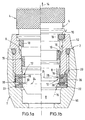
- a plug-in coupling consists of two coupling parts, namely a receiving part 2 and a plug part 4.
- the plug part 4 can be inserted with a plug shaft 6 into a receiving opening 8 of the receiving part 2 and in this case against at least one peripheral seal 10 the receiving opening 8 sealed and lockable against loosening by means of a locking device 12 (movement in the direction of arrow 14 against the direction of insertion).
- the locking device 12 is designed such that on the one hand a partially inserted pre-locking position (Fig.1b) and on the other hand a fully inserted full locking position (Fig.1a) are guaranteed.
- the circumferential seal 10 already bears against the other coupling part in several circumferentially distributed system locations, as shown preferably in the receiving opening 8 of the receiving part 2.
- Axial leakage paths are formed between the contact points. This configuration prevents the circumferential seal 10 from being “washed out” due to the flow.
- the storage locations can - as shown - be formed by a special design of the peripheral seal 10 and / or in an embodiment not shown by a special design of the inner periphery of the receiving opening 8.
- different design features are already contained in the applicant's older, unpublished German patent application 195 36 333.7 from September 29, 1995, to which reference is made in full at this point.
- a further seal 18 can be provided, in particular in the mouth area of the receiving opening 8, which serves to seal against the ingress of dirt, dust, moisture and the like.
- the locking device 12 has a holding element 20, which is seated in a recess 22 of the one coupling part - as shown preferably the receiving part 2 - and in the pre-locking position or in the full locking position each has a locking edge 24 of the other coupling part - as shown preferably the connector part 4 - engages behind in a form-locking manner.
- the recess 22 is formed by an inner ring groove within the receiving opening 8, while the latching edge 24 forms a one-sided delimitation of an outer ring groove on the plug shaft 6.
- the holding element 20 is now designed such that it interacts with the same, single locking edge 24 both in the pre-locking position (FIG. 1b) and in the full locking position (FIG. 1a). This means that the holding element 20 defines both the pre-locking position and the full locking position, although only a single locking edge 24 is present.
- the holding element 20 consists of a cage-like carrier element 26 and two latching elements 28, 30 which are axially adjacent one behind the other and are elastically deformable in the carrier element 26 such that the latching edge 24 is in the pre-latching position according to FIG. 1b of the first latching element 28 and is engaged behind by the second latching element 30 in the fully latched position according to FIG. 1a.
- the carrier element 26 is preferably seated within the recess 22 in the form of an inner ring groove in the receiving opening 8.
- the carrier element 26 is preferably designed as an annular body with two receiving spaces 32 for the latching elements 28, 30.
- the receiving spaces 32 can be formed as cross-slot-like recesses.
- the receiving spaces 32 are inner annular grooves.
- the carrier element 26 is formed as a one-piece or multi-part molded part, in particular from plastic.
- the latching elements 28, 30 and the receiving spaces 32 receiving them can be designed such that the latching elements 28, 30 can be inserted into the receiving spaces 32 from the outside, transversely to the central axis of the carrier element 26 or of the ring body (cf. and 12 arrows 34).
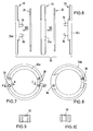
- the latching elements 28, 30 are each slotted spring washers which, because of an interruption in their ring circumference, can be compressed and thereby reduced in diameter in such a way that they are thereby axially directed into the receiving spaces formed as ring grooves 32 can be used.
- the carrier element 26 is in each case a one-piece molded part.
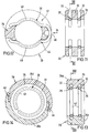
- FIGS. 6 to 10 an advantageous embodiment of the holding element 20 is illustrated in FIGS. 6 to 10, in which the carrier element 26 consists of three carrier parts 26a, b, c which are divided in the axial direction, in particular in each case annular, namely a central part 26a and two side parts 26b, c, which are connected to one another in a “sandwich-like” manner with the interposition of one of the latching elements 28,30.
- a plug-in and / or snap-in connection is preferably provided for this connection, which can be released in particular.
- the side parts 26b, c each engage with plug pins 36 in the axial direction in corresponding plug openings 38 in the central part 26a.
- a defined arrangement can advantageously be achieved by a special arrangement and / or by a special cross-sectional shape of the plug pins 36 and the plug openings 38 such that the individual parts 26a, b, c can only be connected to one another in a defined relative assignment.
- different large plug openings 38 are provided with respect to the diameter, to which the plug pins 36 are adapted accordingly.
- the carrier element 26 consists of two carrier parts 26d, e, which are divided in the circumferential direction, preferably each essentially semi-annular.
- the carrier parts 26d, e are connected to one another, including the latching elements 28, 30, and in particular releasably, preferably via at least one latching connection (snap-fit form or force fit connection 40).
- the carrier element 26 has, at least on its side radially facing the latching edge 24, in particular two diametrically opposed, slot-like openings, which are partially penetrated by the latching elements 28, 30 for engaging behind the latching edge 24.
- the locking elements 28, 30 consist of plastic or metal, in particular spring steel.
- the locking elements 28, 30 in the embodiment according to FIGS. 13 and 14 are of slotted spring washers 42 formed in particular from spring wire circular in cross section. It is a kind of snap rings. This embodiment is characterized by a very simple assembly, compact design and, in the special embodiment according to FIGS. 13 and 14, also by simply releasing it by opening the cage and then removing the latching elements 28, 30.
- the latching elements 28, 30 are each designed as spring clips 44 with two spring arms 48 which are integrally connected via a connecting section 46 which forms a type of spring joint.
- the spring clips 44 are formed as stamped parts made of a relatively thin spring plate. This results in a particularly favorable, short overall length despite the two locking positions.
- the spring clips 44 consist of spring wire which is preferably circular in cross section. The advantage here is that the spring clips 44 can be easily centered within the support member 26. In addition, there is a simple releasability by pulling away to the side (against the direction of the arrow 34). Here too, a very compact design is achieved.
- the spring clips 44 are expediently in the region their spring arms 48, which interact with the locking edge 24, are adapted to the peripheral contour of the coupling part having the locking edge 24, preferably the plug shaft 6. This results in an approximately circular arc-shaped configuration of the latching area of the spring arms 48.
- Fig. 3 the locking element 28 or the spring clip 44 is shown in the lower half of the figure in its "closed” locking position and in the upper half of the figure in the "open” position during the plugging process.
- the locking edge 24 is indicated by a circular chain line.
- the receiving part 2 consists of two releasably connected parts, namely a base part 50 and an insert part 52, these two parts 50, 52 between them Limit holding element 20 receiving recess 22.
- the plug shaft 6, which is locked in one of the two locking positions, can be removed in the opposite direction of the arrow 14 after the insert part 52 has been detached from the base part 50.
- the insert part 52 would form the latching edge 24 which cooperates with the holding element 20 for releasability. A release would then be possible analogously.
- the invention has not yet been limited to the combination of features defined in claim 1, but can also be defined by any other combination of specific features of all the individual features disclosed in total. This means that in principle practically every single feature of claim 1 can be omitted or replaced by at least one single feature disclosed elsewhere in the application. In this respect, claim 1 is only to be understood as a first attempt at formulation for an invention.
Landscapes
- Engineering & Computer Science (AREA)
- General Engineering & Computer Science (AREA)
- Mechanical Engineering (AREA)
- Quick-Acting Or Multi-Walled Pipe Joints (AREA)
Applications Claiming Priority (2)
| Application Number | Priority Date | Filing Date | Title |
|---|---|---|---|
| DE19621535 | 1996-05-29 | ||
| DE19621535A DE19621535A1 (de) | 1996-05-29 | 1996-05-29 | Steckkupplung für Druckmittelsysteme |
Publications (3)
| Publication Number | Publication Date |
|---|---|
| EP0810399A2 true EP0810399A2 (fr) | 1997-12-03 |
| EP0810399A3 EP0810399A3 (fr) | 1998-08-12 |
| EP0810399B1 EP0810399B1 (fr) | 2001-12-05 |
Family
ID=7795586
Family Applications (1)
| Application Number | Title | Priority Date | Filing Date |
|---|---|---|---|
| EP97104112A Expired - Lifetime EP0810399B1 (fr) | 1996-05-29 | 1997-03-12 | Raccord emboítable pour systèmes à fluide sous pression |
Country Status (4)
| Country | Link |
|---|---|
| US (1) | US6027143A (fr) |
| EP (1) | EP0810399B1 (fr) |
| BR (1) | BR9703343A (fr) |
| DE (2) | DE19621535A1 (fr) |
Cited By (3)
| Publication number | Priority date | Publication date | Assignee | Title |
|---|---|---|---|---|
| EP0860642A1 (fr) * | 1997-02-25 | 1998-08-26 | Armaturenfabrik Hermann Voss GmbH + Co. | Raccord rapide pour fluide sous pression |
| WO2008151809A1 (fr) | 2007-06-13 | 2008-12-18 | Knorr-Bremse Systeme für Nutzfahrzeuge GmbH | Raccord pneumatique libérable |
| EP2479470A3 (fr) * | 2008-07-14 | 2012-08-15 | Voss Automotive GmbH | Raccord enfichage pour conduites d'agent sous pression |
Families Citing this family (20)
| Publication number | Priority date | Publication date | Assignee | Title |
|---|---|---|---|---|
| DE19536333A1 (de) | 1995-09-29 | 1997-04-03 | Voss Armaturen | Steckkupplung für Druckmittelsysteme |
| DE29719247U1 (de) | 1997-10-29 | 1999-02-25 | Voss Armaturen | Steckkupplung für Druckmittelsysteme |
| US6293596B1 (en) * | 1999-01-06 | 2001-09-25 | Itt Manufacturing Enterprises, Inc. | Quick connector with after incident indicator clip |
| DE19917396C1 (de) * | 1999-04-16 | 2000-08-17 | Friatec Ag | Steckkupplung |
| US6699233B2 (en) * | 2000-04-10 | 2004-03-02 | Scimed Life Systems, Inc. | Locking catheter |
| SE522656C2 (sv) * | 2000-11-24 | 2004-02-24 | Electrolux Ab | Indikeringsanordning vid en tvättmaskin |
| US6508274B2 (en) | 2000-12-04 | 2003-01-21 | The Goodyear Tire & Rubber Company | Fitting dust plug |
| DE10141315C1 (de) * | 2001-08-28 | 2003-03-20 | Siemens Ag | Kupplung zum Verbinden zweier ein Medium führender Bauteile |
| US6805383B2 (en) * | 2001-11-12 | 2004-10-19 | Itt Manufacturing Enterprises, Inc. | Fluid quick connector with secure electrical contact |
| SE520508C2 (sv) * | 2001-11-15 | 2003-07-15 | Volvo Lastvagnar Ab | Kopplingsanordning för tryckmediumledningar och förfarande för framställning av sådan kopplingsanordning, innefattande läckagespår för indikering av läckage |
| ATE412134T1 (de) * | 2006-02-23 | 2008-11-15 | Voss Automotive Gmbh | Anschlussteil für pneumatische oder hydraulische aggregate |
| DE102006016211A1 (de) * | 2006-04-03 | 2007-10-04 | Novalung Gmbh | Kupplung für rohrförmige Elemente |
| GB2460641B (en) * | 2008-06-02 | 2013-03-13 | Joy Mm Delaware Inc | A clip for pin retention |
| DE202008009399U1 (de) | 2008-07-14 | 2009-11-19 | Voss Automotive Gmbh | Steckkupplung für Druckmittel-Leitungen |
| DE202008009398U1 (de) | 2008-07-14 | 2009-11-19 | Voss Automotive Gmbh | Steckkupplung für Druckmittel-Leitungen |
| JP6131183B2 (ja) * | 2010-05-04 | 2017-05-17 | ノーマ・ユー・エス・ホールディング・リミテッド・ライアビリティ・カンパニーNorma U. S. Holding Llc | コネクタアセンブリ |
| WO2019209860A1 (fr) * | 2018-04-24 | 2019-10-31 | Reliance Worldwide Corporation | Connecteur pour fluide |
| KR102654568B1 (ko) * | 2018-10-01 | 2024-04-03 | 현대자동차주식회사 | 공압 회로용 커넥터 |
| US20230358352A1 (en) * | 2020-10-05 | 2023-11-09 | Oetiker Ny, Inc. | Fluid connector including a connection verification contact |
| DE102022120888A1 (de) * | 2022-08-18 | 2024-02-29 | Voss Automotive Gmbh | "Steckkupplung mit Leckageindikator für Fluidleitungen" |
Citations (3)
| Publication number | Priority date | Publication date | Assignee | Title |
|---|---|---|---|---|
| FR1503989A (fr) * | 1966-10-10 | 1967-12-01 | Staubli Freres & Cie | Dispositif de raccord rapide pour canalisations et applications analogues |
| EP0751331A1 (fr) * | 1995-06-30 | 1997-01-02 | Armaturenfabrik Hermann Voss GmbH + Co. | Raccord emboîtable pour systèmes à fluide sous pression |
| EP0766033A1 (fr) * | 1995-09-29 | 1997-04-02 | Armaturenfabrik Hermann Voss GmbH + Co. | Rapide rapide pour systèmes de fluide sous pression |
Family Cites Families (6)
| Publication number | Priority date | Publication date | Assignee | Title |
|---|---|---|---|---|
| GB714028A (en) * | 1951-11-14 | 1954-08-18 | Oskar Biegel G M B H | Improvements relating to hose couplings |
| GB867749A (en) * | 1958-12-12 | 1961-05-10 | Olin Mathieson | Improvements in or relating to pipe couplings |
| US3453005A (en) * | 1968-04-08 | 1969-07-01 | Scovill Manufacturing Co | Quick-connect safety coupling |
| US3584902A (en) * | 1969-07-09 | 1971-06-15 | Anchor Coupling Co Inc | Quick-connect safety coupling |
| US3929357A (en) * | 1974-11-13 | 1975-12-30 | Gen Motors Corp | Quick connect coupling with tandem snap rings |
| CA1272499A (fr) * | 1986-02-06 | 1990-08-07 | Commander Electrical Materials, Inc. | Raccord pour tubes ondules |
-
1996
- 1996-05-29 DE DE19621535A patent/DE19621535A1/de not_active Withdrawn
-
1997
- 1997-03-12 EP EP97104112A patent/EP0810399B1/fr not_active Expired - Lifetime
- 1997-03-12 DE DE59705616T patent/DE59705616D1/de not_active Expired - Lifetime
- 1997-05-28 US US08/864,589 patent/US6027143A/en not_active Expired - Lifetime
- 1997-05-30 BR BR9703343A patent/BR9703343A/pt not_active IP Right Cessation
Patent Citations (3)
| Publication number | Priority date | Publication date | Assignee | Title |
|---|---|---|---|---|
| FR1503989A (fr) * | 1966-10-10 | 1967-12-01 | Staubli Freres & Cie | Dispositif de raccord rapide pour canalisations et applications analogues |
| EP0751331A1 (fr) * | 1995-06-30 | 1997-01-02 | Armaturenfabrik Hermann Voss GmbH + Co. | Raccord emboîtable pour systèmes à fluide sous pression |
| EP0766033A1 (fr) * | 1995-09-29 | 1997-04-02 | Armaturenfabrik Hermann Voss GmbH + Co. | Rapide rapide pour systèmes de fluide sous pression |
Cited By (4)
| Publication number | Priority date | Publication date | Assignee | Title |
|---|---|---|---|---|
| EP0860642A1 (fr) * | 1997-02-25 | 1998-08-26 | Armaturenfabrik Hermann Voss GmbH + Co. | Raccord rapide pour fluide sous pression |
| WO2008151809A1 (fr) | 2007-06-13 | 2008-12-18 | Knorr-Bremse Systeme für Nutzfahrzeuge GmbH | Raccord pneumatique libérable |
| CN101680585B (zh) * | 2007-06-13 | 2013-05-15 | 克诺尔商用车制动系统有限公司 | 用于制造可拆卸的气动的连接装置的方法 |
| EP2479470A3 (fr) * | 2008-07-14 | 2012-08-15 | Voss Automotive GmbH | Raccord enfichage pour conduites d'agent sous pression |
Also Published As
| Publication number | Publication date |
|---|---|
| BR9703343A (pt) | 1998-09-01 |
| US6027143A (en) | 2000-02-22 |
| EP0810399A3 (fr) | 1998-08-12 |
| DE19621535A1 (de) | 1997-12-04 |
| EP0810399B1 (fr) | 2001-12-05 |
| DE59705616D1 (de) | 2002-01-17 |
Similar Documents
| Publication | Publication Date | Title |
|---|---|---|
| EP0810399A2 (fr) | Raccord emboîtable pour systèmes à fluide sous pression | |
| EP1697675B1 (fr) | Raccord a emboitement pour conduites de fluide | |
| EP0728979B1 (fr) | Raccord étanche entre un tuyau en matière plastique et une pièce de raccordement fabriquée en métal | |
| EP0733844B1 (fr) | Dispositif de connexion pour conduites | |
| EP0816741A2 (fr) | Raccordement par emboítement | |
| DE102008013565A1 (de) | Einsteckkupplung | |
| EP0748975B1 (fr) | Connecteur à emboítement pour systèmes à fluide sous pression | |
| EP1296089B9 (fr) | Dispositif de raccord pour tuyaux pour fluide | |
| EP2158935A1 (fr) | Connecteur à fiche pour tuyaux médicaux | |
| EP0247214B1 (fr) | Raccord embrochable pour une connexion détachable d'une conduite en matière plastique avec un élément de serrage | |
| EP0766033B1 (fr) | Rapide rapide pour systèmes de fluide sous pression | |
| EP2479470B1 (fr) | Raccord enfichage pour conduites d'agent sous pression | |
| EP1636521B1 (fr) | Dispositif de raccordement pour un tuyau ou un element similaire | |
| EP0280180B1 (fr) | Raccord à emboîtement détachable pour tuyaux | |
| EP0618393B1 (fr) | Dispositif de raccordement pour tuyaux flexibles et/ou tuyaux rigides | |
| DE4240279C2 (de) | Anschlußvorrichtung für Schlauch- und/oder Rohrleitungen | |
| EP0579141A1 (fr) | Montage automatique d'un accouplement enfichable pour tuyaux flexibles dans des véhicules automobiles | |
| EP0751330B1 (fr) | Raccord emboítable pour systèmes à fluide sous pression | |
| DE4343112B4 (de) | Membranfederkupplung mit durch Zungen abgestützter Membranfeder | |
| EP0751332B1 (fr) | Raccord emboítable pour systèmes sous pression | |
| EP0751331B1 (fr) | Raccord emboítable pour systèmes à fluide sous pression | |
| EP0813017A2 (fr) | Raccord emboitable pour systèmes sous pression | |
| EP1006307A1 (fr) | Raccord enfichable | |
| EP0647803A1 (fr) | Raccord emboîtable pour un système à fluide sous pression | |
| DE202009005674U1 (de) | Vorrichtung zum schwenkbaren Verbinden von zwei Leitungsabschnitten |
Legal Events
| Date | Code | Title | Description |
|---|---|---|---|
| PUAI | Public reference made under article 153(3) epc to a published international application that has entered the european phase |
Free format text: ORIGINAL CODE: 0009012 |
|
| AK | Designated contracting states |
Kind code of ref document: A2 Designated state(s): DE FR GB IT NL SE |
|
| ITCL | It: translation for ep claims filed |
Representative=s name: ING. A. GIAMBROCONO & C. S.R.L. |
|
| EL | Fr: translation of claims filed | ||
| GBC | Gb: translation of claims filed (gb section 78(7)/1977) | ||
| TCNL | Nl: translation of patent claims filed | ||
| PUAL | Search report despatched |
Free format text: ORIGINAL CODE: 0009013 |
|
| AK | Designated contracting states |
Kind code of ref document: A3 Designated state(s): DE FR GB IT NL SE |
|
| 17P | Request for examination filed |
Effective date: 19980904 |
|
| 17Q | First examination report despatched |
Effective date: 20000127 |
|
| GRAG | Despatch of communication of intention to grant |
Free format text: ORIGINAL CODE: EPIDOS AGRA |
|
| GRAG | Despatch of communication of intention to grant |
Free format text: ORIGINAL CODE: EPIDOS AGRA |
|
| GRAH | Despatch of communication of intention to grant a patent |
Free format text: ORIGINAL CODE: EPIDOS IGRA |
|
| RAP1 | Party data changed (applicant data changed or rights of an application transferred) |
Owner name: ARMATURENFABRIK HERMANN VOSS GMBH + CO. KG |
|
| GRAH | Despatch of communication of intention to grant a patent |
Free format text: ORIGINAL CODE: EPIDOS IGRA |
|
| GRAA | (expected) grant |
Free format text: ORIGINAL CODE: 0009210 |
|
| AK | Designated contracting states |
Kind code of ref document: B1 Designated state(s): DE FR GB IT NL SE |
|
| REG | Reference to a national code |
Ref country code: GB Ref legal event code: IF02 |
|
| REF | Corresponds to: |
Ref document number: 59705616 Country of ref document: DE Date of ref document: 20020117 |
|
| GBT | Gb: translation of ep patent filed (gb section 77(6)(a)/1977) |
Effective date: 20020301 |
|
| PLBE | No opposition filed within time limit |
Free format text: ORIGINAL CODE: 0009261 |
|
| STAA | Information on the status of an ep patent application or granted ep patent |
Free format text: STATUS: NO OPPOSITION FILED WITHIN TIME LIMIT |
|
| 26N | No opposition filed | ||
| NLT1 | Nl: modifications of names registered in virtue of documents presented to the patent office pursuant to art. 16 a, paragraph 1 |
Owner name: VOSS AUTOMOTIVE GMBH |
|
| REG | Reference to a national code |
Ref country code: FR Ref legal event code: CD |
|
| PGFP | Annual fee paid to national office [announced via postgrant information from national office to epo] |
Ref country code: GB Payment date: 20110323 Year of fee payment: 15 |
|
| GBPC | Gb: european patent ceased through non-payment of renewal fee |
Effective date: 20120312 |
|
| PG25 | Lapsed in a contracting state [announced via postgrant information from national office to epo] |
Ref country code: GB Free format text: LAPSE BECAUSE OF NON-PAYMENT OF DUE FEES Effective date: 20120312 |
|
| REG | Reference to a national code |
Ref country code: FR Ref legal event code: PLFP Year of fee payment: 20 |
|
| PGFP | Annual fee paid to national office [announced via postgrant information from national office to epo] |
Ref country code: NL Payment date: 20160310 Year of fee payment: 20 |
|
| PGFP | Annual fee paid to national office [announced via postgrant information from national office to epo] |
Ref country code: SE Payment date: 20160311 Year of fee payment: 20 Ref country code: FR Payment date: 20160309 Year of fee payment: 20 |
|
| PGFP | Annual fee paid to national office [announced via postgrant information from national office to epo] |
Ref country code: DE Payment date: 20160531 Year of fee payment: 20 |
|
| PGFP | Annual fee paid to national office [announced via postgrant information from national office to epo] |
Ref country code: IT Payment date: 20160324 Year of fee payment: 20 |
|
| REG | Reference to a national code |
Ref country code: DE Ref legal event code: R071 Ref document number: 59705616 Country of ref document: DE |
|
| REG | Reference to a national code |
Ref country code: NL Ref legal event code: MK Effective date: 20170311 |
|
| REG | Reference to a national code |
Ref country code: SE Ref legal event code: EUG |