EP0810311B1 - Loom for the realisation of ornamental fringes - Google Patents
Loom for the realisation of ornamental fringes Download PDFInfo
- Publication number
- EP0810311B1 EP0810311B1 EP97420079A EP97420079A EP0810311B1 EP 0810311 B1 EP0810311 B1 EP 0810311B1 EP 97420079 A EP97420079 A EP 97420079A EP 97420079 A EP97420079 A EP 97420079A EP 0810311 B1 EP0810311 B1 EP 0810311B1
- Authority
- EP
- European Patent Office
- Prior art keywords
- stops
- hook
- carrying
- fringes
- loom
- Prior art date
- Legal status (The legal status is an assumption and is not a legal conclusion. Google has not performed a legal analysis and makes no representation as to the accuracy of the status listed.)
- Expired - Lifetime
Links
Images


Classifications
-
- D—TEXTILES; PAPER
- D04—BRAIDING; LACE-MAKING; KNITTING; TRIMMINGS; NON-WOVEN FABRICS
- D04D—TRIMMINGS; RIBBONS, TAPES OR BANDS, NOT OTHERWISE PROVIDED FOR
- D04D5/00—Fringes
-
- D—TEXTILES; PAPER
- D03—WEAVING
- D03D—WOVEN FABRICS; METHODS OF WEAVING; LOOMS
- D03D41/00—Looms not otherwise provided for, e.g. for weaving chenille yarn; Details peculiar to these looms
Definitions
- the invention relates to the manufacture of fringes with braided heads.
- each plied cord forming a fringe also wraps a selvedge core which is perpendicular to the fringes, and the heads fringes are linked to each other by two layers of interwoven warp threads.
- This type of fringes with braided head differs from the fringes made on shuttle craft in which the fringe heads are linked on both sides of two layers of chain son forming a selvedge without a longitudinal core, and are therefore apparent.
- the manufacture of fringes with a braided head is carried out by means of looms specials comprising, perpendicular to a longitudinal frame, a support carrying a core cord reel, a rotating reel carrying twisted spools of cords for the fringes, means returning the bundles of cords parallel to the longitudinal direction of movement of two layers of chain son.
- a reciprocating hook grips one of the twisted cords wrapping around the core to pass it between the two layers and form a bangs, before going to grab another cord.
- the object of the present invention is to remedy these drawbacks by providing a loom making it possible to carry out, automatically, the fringes with head braided with undulations.
- the rod of the fringing hook is mounted with the possibility of declutching relative to its drive means in translation and comprises, at its end opposite to that of the hook, a heel capable of come, at the end of the fringing stroke, bearing on at least one of the abutment faces a member movable sequentially to modify the stroke of the hook in relation with the shape of the wave to be given to the wave of the fringes.
- each fringe over a longer length or shorter is determined according to the contact of the heel of the hook rod with one of the abutment faces and can vary by changing the position longitudinal of the abutment face coming into contact with this heel.
- the hook is arranged at the end of the front rod of a double-acting pneumatic cylinder with double rods, the rear rod carries the heel cooperating with the member carrying the stops.
- a loom for the manufacture of head bangs braided is composed of a frame 2 carrying laterally a frame 3 supporting a plate 4 on which is mounted free in rotation a reel 5 for the plied cord 6 constituting the soul of the braided head.
- the chassis 3 also carries a rotary drum 7 around a tubular axis 8 crossed by the cord 6 constituting the core.
- This reel synchronized with the trade, has cheeks 7a, 7b and carries several coils 9 of twisted cords 10.
- the unwinding of each cord 10 is controlled by a mechanism 12.
- Each cord 10 crosses the downstream cheek 7b of the drum 7 to come, with the others cords 10 and the core cord 6, on a member 13 returning these cords in parallel to the direction of movement of the work on the loom, represented by the arrow 14 to Figure 1.
- the frame 2 supports means 15 for vertical guidance of at least two heddle frames 16 determining the position of two layers of chain son 17 reel of reels 18.
- the invention relates to the conditions of displacement of the hook 19.
- this hook is formed at the end of the front rod 30 of a pneumatic cylinder 32, double acting and double rods, the rear rod 33 of which has a stop heel 33a.
- This heel cooperates with abutment faces 34a, 34b, 34c, 34d, ... which can each be brought in its path and carried by a member which, in the embodiment shown in Figure 1, is constituted by a plate 35, rotatable about an axis parallel to the direction of displacement of the cylinder hook and rods.
- This plate is wedged on a shaft 36 linked in rotation to a stepping motor 37.
- This motor and the jack 32 are carried by the frame 2.
- the supply in the opposite direction to the jack 32 automatically brings the piston in front end-of-travel stop and therefore guarantees the positioning of the hook 19 in the ply of plied cords 10, and in particular the attachment of the plied cord further forward.
- This simple device allows continuous, completely automatic, fringes with braided heads in which the length of the fringes varies.
- the stops 34a, 34b, 34c, 34d, ... are fixed on a slide 40, movable longitudinally in a slide 41 of the frame, for example by a pneumatic or electric jack 42, which can be moved step by step, by a value equal to the step between the abovementioned stops.
- FIG. 4 shows the application of the device according to the invention to current mechanism, consisting of a hook 19 formed at the end of a curved rod 50, secured to an arm 52 projecting radially from a vertical axis 53, connected to means 54 capable of rotating it alternately in one direction or the other on a fragment of a circle.
- the rotation link between the axis 53 and the crown of the drive means 54 is not positive but is carried out with interposition of a torque limiter, a friction clutch, or any other means allowing, beyond a value of the resistant force, the relative angular displacement of the crown of the drive means 54 relative to the axis 53.
- spring means 56 When returning in the opposite direction, spring means 56 maintain the heel 50a against its stop 34a, as long as a stop 57 of the crown of the means 54 does not does not come into contact with the arm 52.
- the stop cooperating with the heel 33a or 50a is constituted by the free end 60a of a screw 60 locked in rotation in the frame 2, for example by a key 62, but free in translation.
- This screw is placed in a ball nut 63 which, wedged in translation but free to rotate in the frame 2, is linked to a toothed pulley 64.
- a toothed belt 65 connects this pulley to a toothed pinion 66 wedged on the shaft of output of an electric stepper motor 67, with two directions of rotation.
- the supply of the motor 67 causes, by the transmission of movement 64 to 66, the rotation on a fraction of a turn of the nut 63, and consequence of the longitudinal displacement of the screw 60, therefore the modification of the longitudinal position of its end forming a stop 60a.
- the member carrying the faces of stops consists of a rotary cam 72 wedged on the shaft of an electric motor 73 swivel by one turn for a manufacturing cycle.
- the abutment faces 70a, 70b, 70c, ... consist of point bearing surfaces of the peripheral face of the cam 72.
- the device according to the invention enables head fringes to be produced automatically braided with undulations and that these undulations may have different shapes.
Description
L'invention est relative à la fabrication de franges à têtes gansées.The invention relates to the manufacture of fringes with braided heads.
Dans ce type de franges, chaque cordon retors formant une frange enveloppe également une âme de lisière qui est perpendiculaire aux franges, et les têtes des franges sont liées les unes aux autres par deux nappes de fils de chaíne entrecroisés.In this type of fringes, each plied cord forming a fringe also wraps a selvedge core which is perpendicular to the fringes, and the heads fringes are linked to each other by two layers of interwoven warp threads.
Ce type de franges à tête gansée se différencie des franges réalisées sur métier à navettes dans lesquelles les têtes de franges sont liées de part et d'autre de deux nappes de fils de chaínes formant une lisière sans âme longitudinale, et sont donc apparentes.This type of fringes with braided head differs from the fringes made on shuttle craft in which the fringe heads are linked on both sides of two layers of chain son forming a selvedge without a longitudinal core, and are therefore apparent.
La fabrication des franges à tête gansée est réalisée au moyen de métiers spéciaux comprenant, perpendiculairement à un bâti longitudinal, un support portant un dévidoir du cordon d'âme, un touret rotatif portant des bobineaux de cordons retors pour les franges, des moyens renvoyant les faisceaux de cordons parallèlement à la direction longitudinale de déplacement de deux nappes de fils de chaíne. Dans ces métiers, un crochet à mouvement alternatif vient saisir l'un des cordons retors s'enroulant autour de l'âme pour le faire passer entre les deux nappes et former une frange, avant d'aller saisir un autre cordon.The manufacture of fringes with a braided head is carried out by means of looms specials comprising, perpendicular to a longitudinal frame, a support carrying a core cord reel, a rotating reel carrying twisted spools of cords for the fringes, means returning the bundles of cords parallel to the longitudinal direction of movement of two layers of chain son. In these looms, a reciprocating hook grips one of the twisted cords wrapping around the core to pass it between the two layers and form a bangs, before going to grab another cord.
Ces métiers ne permettent de réaliser, de manière automatique, que des franges ayant des longueurs constantes. Il en résulte que pour réaliser des franges de longueur variable, celles-ci doivent être tirées manuellement une à une avec une ampleur dépendant du motif devant être réalisé. L'intervention manuelle réduit considérablement la cadence de fabrication de telles franges et augmente leur coût de fabrication, de sorte que les franges formant des ondulations ont une application très limitée.These trades make it possible to carry out, automatically, only fringes having constant lengths. It follows that to achieve fringes of variable length, these must be pulled manually one by one with a extent depending on the motif to be produced. Reduced manual intervention considerably the production rate of such fringes and increases their cost by manufacturing, so that the fringes forming corrugations have a very limited.
Le document US-A-3 301 204 décrit un métier capable de prévoir une frange formant des ondulations, la longueur de chaque boucle de la frange étant réglée par une tige reposant sur une came rotative.Document US-A-3,301,204 describes a trade capable of providing for a fringe forming ripples, the length of each loop of the fringe being adjusted by a rod resting on a rotary cam.
La présente invention a pour but de remédier à ces inconvénients en fournissant un métier permettant de réaliser, de manière automatique, les franges à tête gansée présentant des ondulations.The object of the present invention is to remedy these drawbacks by providing a loom making it possible to carry out, automatically, the fringes with head braided with undulations.
A cet effet, dans le métier selon l'invention, la tige du crochet frangeur est montée avec possibilité de débrayage par rapport à ses moyens d'entraínement en translation et comporte, à son extrémité opposée à celle du crochet, un talon apte à venir, en fin de course de frangeage, en appui sur au moins l'une des faces de butées d'un organe déplaçable séquentiellement pour modifier la course du crochet en rapport avec la forme de l'ondulation devant être donnée à l'ondulation des franges.To this end, in the loom according to the invention, the rod of the fringing hook is mounted with the possibility of declutching relative to its drive means in translation and comprises, at its end opposite to that of the hook, a heel capable of come, at the end of the fringing stroke, bearing on at least one of the abutment faces a member movable sequentially to modify the stroke of the hook in relation with the shape of the wave to be given to the wave of the fringes.
Avec cet agencement, la formation de chaque frange sur une longueur plus ou moins longue est déterminée en fonction du contact du talon de la tige du crochet avec l'une des faces de butées et peut varier par modification de la position longitudinale de la face de butée venant en contact avec ce talon.With this arrangement, the formation of each fringe over a longer length or shorter is determined according to the contact of the heel of the hook rod with one of the abutment faces and can vary by changing the position longitudinal of the abutment face coming into contact with this heel.
Dans une forme d'exécution de l'invention, le crochet est ménagé à l'extrémité de la tige avant d'un vérin pneumatique à double effet et à double tiges dont la tige arrière porte le talon coopérant avec l'organe portant les butées.In one embodiment of the invention, the hook is arranged at the end of the front rod of a double-acting pneumatic cylinder with double rods, the rear rod carries the heel cooperating with the member carrying the stops.
Avec cet agencement, le débrayage s'effectue pneumatiquement.With this arrangement, the declutching takes place pneumatically.
D'autres caractéristiques et avantages ressortiront de la description qui suit
en référence au dessin schématique annexé représentant, à titre d'exemples non
limitatifs, plusieurs formes d'exécution du dispositif selon l'invention.
Comme montré à la figure 1, un métier pour la fabrication de franges à tête
gansée est composé d'un bâti 2 portant latéralement un châssis 3 supportant une platine
4 sur laquelle est monté libre en rotation un dévidoir 5 pour le cordon retors 6
constituant l'âme de la tête gansée. Le châssis 3 porte également un touret 7 rotatif
autour d'un axe tubulaire 8 traversé par le cordon 6 constituant l'âme. Ce touret,
synchronisé avec le métier, est muni de joues 7a, 7b et porte plusieurs bobineaux 9 de
cordons retors 10. Le dévidage de chaque cordon 10 est contrôlé par un mécanisme 12.
Chaque cordon 10 traverse la joue aval 7b du touret 7 pour venir, avec les autres
cordons 10 et le cordon d'âme 6, sur un organe 13 renvoyant ces cordons parallèlement
à la direction des déplacements de l'ouvrage sur le métier, représenté par la flèche 14 à
la figure 1.As shown in Figure 1, a loom for the manufacture of head bangs
braided is composed of a
Le bâti 2 supporte des moyens 15 de guidage vertical d'au moins deux
cadres à lisses 16 déterminant la position de deux nappes de fils de chaíne 17 se
dévidant de bobines 18. Un crochet 19, mobile en translation longitudinale,
alternativement dans un sens ou dans l'autre, vient saisir successivement chacun des
cordons retors 10 pour former, sur la table de travail 20, les franges 22 de l'ouvrage 23.
Pendant que le crochet 19 est hors des deux nappes de fils de chaíne 17, les cadres à
lisses 16 sont déplacés pour assurer, par entrecroisement des nappes 17, la liaison des
têtes 22a des franges 22. Cette liaison est effectuée au ras de la tête gansée 24,
composée du cordon d'âme 6 sur lequel sont enroulés les cordons retors 10, quand ils ne
forment pas les franges 22.The
L'invention est relative aux conditions de déplacement du crochet 19.The invention relates to the conditions of displacement of the
Dans la forme d'exécution représentée à la figure 1, ce crochet est ménagé
à l'extrémité de la tige avant 30 d'un vérin pneumatique 32, à double effet et à double
tiges, dont la tige arrière 33 comporte un talon de butée 33a. Ce talon coopère avec les
faces de butées 34a, 34b, 34c, 34d, ... pouvant chacune être amenées dans sa trajectoire
et portées par un organe qui, dans la forme d'exécution représenté à la figure 1, est
constitué par un plateau 35, rotatif autour d'un axe parallèle à la direction de
déplacement du crochet et des tiges du vérin. Ce plateau est calé sur un arbre 36 lié en
rotation à un moteur pas à pas 37. Ce moteur et le vérin 32 sont portés par le bâti 2. Les
diverses butées 34a, 34b, 34c, 34d,..font saillies de la face du plateau en vis à vis du
talon 33a et sont réparties sur un même cercle, avec un pas angulaire P constant (figure
2). Elles se différencient par leur longueur en saillie. Ces butées peuvent, par exemple,
être constituées par des vis, vissées dans des alésages taraudés du plateau et dont la tête
est apte à venir en contact avec le talon 33a précité.In the embodiment shown in Figure 1, this hook is formed
at the end of the
Lorsque le vérin pneumatique 32 est alimenté pour se déplacer dans le
sens de la flèche 31 de figure 1, après que le crochet 19, ménagé à l'extrémité de sa tige
30, ait saisi l'un des cordons retors 6, la course du piston et des deux tiges 30 et 33 et,
en conséquence, celle du crochet 19, donc la longueur de la frange en cours de
réalisation, est déterminée par l'intervalle entre le talon 33a et la butée 34a, 34b, 34c, ...
lui faisant vis à vis. On conçoit ainsi que, pour modifier la longueur des franges, il
suffit de faire pivoter le plateau 35 au moyen du moteur pas à pas 37, pour amener dans
la trajectoire du talon 33a une butée plus ou moins longue en fonction de la forme de
l'ondulation retenue.When the
On notera que, lorsque le talon 33a vient en contact avec la butée, alors
que le piston du vérin n'a pas terminé sa course, cela est sans incidence sur le
fonctionnement du vérin 32 qui, soit accepte la surpression interne, soit comporte sur
son circuit d'alimentation une soupape de décharge automatique, et, en d'autre terme, se
comporte comme un débrayage.Note that, when the
L'alimentation en sens inverse du vérin 32 amène automatiquement le
piston en butée de fin de course avant et garantit donc le positionnement du crochet 19
dans la nappe de cordons retors 10, et en particulier l'accrochage du cordon retors le
plus en avant.The supply in the opposite direction to the
Pour modifier le dessin des ondulations formées par les extrémités libres
des franges 22, il suffit de modifier la longueur des butées, et éventuellement l'angle de
rotation du plateau 35, par exemple, en le faisant pivoter de plus d'un pas.To modify the design of the undulations formed by the
Ce dispositif simple permet de réaliser en continu, de manière entièrement automatique, des franges à têtes gansées dans lesquelles la longueur des franges varie.This simple device allows continuous, completely automatic, fringes with braided heads in which the length of the fringes varies.
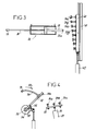
A la figure 3, les butées 34a, 34b, 34c, 34d, ... sont fixées sur un
coulisseau 40, déplaçable longitudinalement dans une glissière 41 du bâti, par exemple
par un vérin 42, pneumatique ou électrique, pouvant être déplacé pas à pas, d'une
valeur égale au pas entre les butées précitées.In FIG. 3, the
La figure 4 montre l'application du dispositif selon l'invention au
mécanisme actuel, composé d'un crochet 19 ménagé à l'extrémité d'une tige cintrée 50,
solidaire d'un bras 52 saillant radialement d'un axe vertical 53, relié à des moyens
d'entraínement 54 aptes à le faire pivoter alternativement dans un sens ou dans l'autre
sur un fragment de cercle.FIG. 4 shows the application of the device according to the invention to
current mechanism, consisting of a
Dans cette forme d'exécution, la liaison en rotation entre l'axe 53 et la
couronne des moyens d'entraínement 54 n'est pas positive mais est réalisée avec
interposition d'un limiteur de couple, d'un embrayage à friction, ou de tout autre moyen
permettant, au-delà d'une valeur de l'effort résistant, le déplacement angulaire relatif de
la couronne des moyens d'entraínement 54 par rapport à l'axe 53.In this embodiment, the rotation link between the
Ainsi, lorsque les moyens 54 entraínent l'arbre 53 dans le sens de la flèche
55, et que le talon 50a de la tige 50 vient buter contre l'une des butées 34a, 34b, 34c,
34d, ... portée par un plateau circulaire 35, ou par tout autre moyen portant des butées de
longueur réglable, ces moyens d'entraínement 54 peuvent terminer leur course, sans
que le mécanisme ne subisse un dommage.Thus, when the
Lors du retour en sens inverse, des moyens à ressort 56 maintiennent le
talon 50a contre sa butée 34a, tant qu'une butée 57 de la couronne des moyens 54 ne
vient pas en contact avec le bras 52.When returning in the opposite direction, spring means 56 maintain the
A la figure 5, la butée coopérant avec le talon 33a ou 50a est constituée par
l'extrémité libre 60a d'une vis 60 calée en rotation dans le bâti 2, par exemple par une
clavette 62, mais libre en translation. Cette vis est disposée dans un écrou à billes 63
qui, calé en translation mais libre en rotation dans le bâti 2, est lié à une poulie crantée
64. Une courroie crantrée 65 relie cette poulie à un pignon cranté 66 calé sur l'arbre de
sortie d'un moteur électrique pas à pas 67, à deux sens de rotation. In FIG. 5, the stop cooperating with the
Ainsi, l'alimentation du moteur 67 provoque, par la transmission de
mouvement 64 à 66, la rotation sur une fraction de tour de l'écrou 63, et en
conséquence le déplacement longitudinal de la vis 60, donc la modification de la
position longitudinale de son extrémité formant butée 60a.Thus, the supply of the motor 67 causes, by the transmission of
Dans la forme d'exécution de la figure 6, l'organe portant les faces de
butées est constitué par une came rotative 72 calée sur l'arbre d'un moteur électrique 73
pivotant d'un tour pour un cycle de fabrication. Les faces de butées 70a, 70b, 70c, ...
sont constituées par des portées ponctuelles de la face périphérique de la came 72.In the embodiment of Figure 6, the member carrying the faces of
stops consists of a
Il ressort de ce qui précède que, quelle que soit sa forme d'exécution, le dispositif selon l'invention permet de réaliser de manière automatique des franges à tête gansée présentant des ondulations et que ces ondulations peuvent présenter différentes formes.It follows from the above that, whatever its form of execution, the device according to the invention enables head fringes to be produced automatically braided with undulations and that these undulations may have different shapes.
Claims (7)
- Loom for producing fringes with a corded head, comprising, perpendicularly to a longitudinal frame (2), a support (3) carrying a reel (5) of a core strand (6), a rotating drum (7) carrying spools (9) of twisted strands (10) for the fringes, means (13) returning the bundles of strands (6, 10) parallel to the longitudinal direction of displacement of two layers (17) of warp yarn, loom in which a hook (19) with reciprocating motion catches one of the twisted strands (10) winding round the core (6) to cause it to pass between the two layers (17) and form a fringe (22), before catching another strand, characterized in that the shaft (30, 50) of the fringing hook (19) is equipped with the possibility of disengaging with respect to its traction means (32, 52) and comprises, at its end opposite to that of the hook (19), a heel (33a, 50a) capable of coming to rest, at the end of the fringing stroke, on at least one of the faces of stops (34a, 34b, 60a, 70a) of a device (35, 40, 60, 72) which can be displaced sequentially to modify the stroke of the hook according to the shape of the waviness to be given to the fringes.
- Loom according to claim 1, characterized in that the hook (19) is arranged on the front shaft (30) of a pneumatic jack (32), with a double action and two shafts, of which the rear shaft (33) carries the heel (33a) co-operating with the device (35, 40, 60, 70) carrying the stops (34a, 34b, ... 60a and 70a).
- Loom according to claim 1, characterized in that, with a hook (19) arranged on a curved shaft (50) connected by an arm (52) projecting radially from an axis (53) to means (54) capable of moving it in circular translation over an arc of a circle and alternately in one direction or in the other, the rotary link between the axis (53) and the traction means (54) is achieved with interpolation of a clutch, while the arm (52) is subjected to the action of a spring means (56) returning it back against a stop (57) of the traction means (54).
- Loom according to any one of claims 1 to 3, characterized in that the device carrying the stops (34a, 34b, ...) comprises a plate (35) which, rotating round an axis substantially parallel to the direction of displacement of the shaft, is connected to means (37) capable of causing it to pivot stepwise, this plate carrying in projection from its face turned in the direction of the heel (33a, 50a) adjustable stops (34a, 34b) of different lengths and angularly spaced at the value of one step of rotation of the plate (35).
- Loom according to any one of claims 1 to 3, characterized in that the device carrying the stops comprises a slide (40) mounted in a sliding manner in a guide (41) of the frame (2) and carrying adjustable stops (34a, 34b) of different lengths, these stops being longitudinally spaced on the slide with a constant step (n) of a value equal to the displacement step of the driving means (42).
- Loom according to any one of claims 1 to 3, characterized in that the device carrying the stops comprises a screw (60), locked in rotation but free in translation in the frame (2), this screw co-operating with a nut (63) which, locked in translation but free in rotation in the frame (2), is connected by motion transmission (64 to 66) to the output spindle of a stepping electric motor (67) with two directions of rotation.
- Loom according to any one of claims 1 to 3, characterized in that the device carrying the stop faces comprises a rotary cam (72) locked on the spindle of an electric motor (73) pivoting one turn per production cycle.
Applications Claiming Priority (2)
| Application Number | Priority Date | Filing Date | Title |
|---|---|---|---|
| FR9606962 | 1996-05-31 | ||
| FR9606962A FR2749326B1 (en) | 1996-05-31 | 1996-05-31 | BUSINESS FOR THE PRODUCTION OF FRINGED HEADS |
Publications (2)
| Publication Number | Publication Date |
|---|---|
| EP0810311A1 EP0810311A1 (en) | 1997-12-03 |
| EP0810311B1 true EP0810311B1 (en) | 2000-11-02 |
Family
ID=9492758
Family Applications (1)
| Application Number | Title | Priority Date | Filing Date |
|---|---|---|---|
| EP97420079A Expired - Lifetime EP0810311B1 (en) | 1996-05-31 | 1997-05-27 | Loom for the realisation of ornamental fringes |
Country Status (4)
| Country | Link |
|---|---|
| US (1) | US5829486A (en) |
| EP (1) | EP0810311B1 (en) |
| DE (1) | DE69703412D1 (en) |
| FR (1) | FR2749326B1 (en) |
Families Citing this family (2)
| Publication number | Priority date | Publication date | Assignee | Title |
|---|---|---|---|---|
| AT502814B1 (en) * | 2005-11-14 | 2007-06-15 | Karl Ronald Schoeller | Rollband contact unit for permanent or movement-dependent intermittent electromechanical galvanic connection of two systems, has leaf springs for pressing different bearings provided in suitable contact areas |
| CN102602747B (en) * | 2012-03-16 | 2013-06-26 | 浙江海森纺机科技有限公司 | Wire storing pipe assembling-disassembling device of cord-knitted knotless net winding machine |
Family Cites Families (10)
| Publication number | Priority date | Publication date | Assignee | Title |
|---|---|---|---|---|
| US1044226A (en) * | 1912-02-13 | 1912-11-12 | Hensel Silk Mfg Company | Fringe-loom. |
| US1530600A (en) * | 1924-06-27 | 1925-03-24 | Jenny Adolph | Fringe-weaving loom |
| US1746790A (en) * | 1927-08-26 | 1930-02-11 | Philip N Newman | Fringe |
| US3186442A (en) * | 1961-09-07 | 1965-06-01 | Gale Harold Graeme | Apparatus and method for forming a decorative fringe |
| US3152620A (en) * | 1962-09-26 | 1964-10-13 | John D Riordan | Woven narrow web with ornamental selvage |
| US3301204A (en) * | 1964-01-31 | 1967-01-31 | Bell Ind Inc | Mechanism for forming a scallop fringe |
| US3391595A (en) * | 1965-08-10 | 1968-07-09 | Iwai Yasuaki | Tufted cord for rugs |
| US3792899A (en) * | 1972-12-29 | 1974-02-19 | Wicker Works | Woven and braided furniture |
| GB2078795A (en) * | 1980-06-26 | 1982-01-13 | Day J & Co Derby Works Ltd | Combined knitting and weaving process for fabric forming |
| US4881444A (en) * | 1988-06-24 | 1989-11-21 | Krauland Konrad L | Method and apparatus for braiding three-dimensional fabrics |
-
1996
- 1996-05-31 FR FR9606962A patent/FR2749326B1/en not_active Expired - Fee Related
-
1997
- 1997-05-27 EP EP97420079A patent/EP0810311B1/en not_active Expired - Lifetime
- 1997-05-27 DE DE69703412T patent/DE69703412D1/en not_active Expired - Lifetime
- 1997-06-02 US US08/867,529 patent/US5829486A/en not_active Expired - Fee Related
Also Published As
| Publication number | Publication date |
|---|---|
| US5829486A (en) | 1998-11-03 |
| DE69703412D1 (en) | 2000-12-07 |
| FR2749326B1 (en) | 1998-08-07 |
| EP0810311A1 (en) | 1997-12-03 |
| FR2749326A1 (en) | 1997-12-05 |
Similar Documents
| Publication | Publication Date | Title |
|---|---|---|
| CA2124311C (en) | Machine for winding/laying down, at simultaneous contact, a plurality of individual threads | |
| EP0046427B1 (en) | Round-bale twine wrapping mechanism | |
| EP0810311B1 (en) | Loom for the realisation of ornamental fringes | |
| BE1003884A5 (en) | Tufting PROCESS AND DEVICE FOR IMPLEMENTING THE METHOD. | |
| EP0795504B1 (en) | Continuous unwinder for bobbins with at least one means for simultaneously unwinding of two bobbins in twin or co-axial arrangement | |
| FR2514211A1 (en) | STATORS COILING APPARATUS | |
| CA2513806C (en) | Released motion winding machine for thermoplastic fibres | |
| EP0363295B1 (en) | Device for cutting and uniting a moving web on a mandrel in continuous-winding machines | |
| FR2585683A1 (en) | Drive device for a system guiding sheets of flexible material which are intended to form a three-dimensional assembly | |
| FR1310490A (en) | Improvements to looms with fixed weft reserve | |
| BE1003829A6 (en) | Method and device for making a carpet knotted. | |
| FR2537556A1 (en) | Automatic machine for winding small tori | |
| FR2502195A1 (en) | Fantasy yarn - comprises core yarn with twisted wrapping of effect yarn, with localised areas of triple winding | |
| FR2639366A1 (en) | Weaving loom equipped with a tension regulator for a roll for paying out or winding on a textile web | |
| BE551340A (en) | ||
| BE514488A (en) | ||
| EP0320388A1 (en) | Reel for bundles of connector wires disposed in layers | |
| FR2501245A1 (en) | METHOD AND DEVICE FOR WELDING | |
| EP0059815B1 (en) | Binding-twine controlling device for a round-baling press | |
| FR2621570A1 (en) | Device enabling the rewinding means on a textile machine to be controlled | |
| CH495444A (en) | Loom | |
| FR2743358A1 (en) | Bobbin winder which can be easily and rapidly set | |
| EP0022037A1 (en) | Process for winding textile material | |
| BE435067A (en) | ||
| FR2586528A1 (en) | Fishing reel equipped with a speed changing device |
Legal Events
| Date | Code | Title | Description |
|---|---|---|---|
| PUAI | Public reference made under article 153(3) epc to a published international application that has entered the european phase |
Free format text: ORIGINAL CODE: 0009012 |
|
| 17P | Request for examination filed |
Effective date: 19970924 |
|
| AK | Designated contracting states |
Kind code of ref document: A1 Designated state(s): BE DE ES FR GB IT |
|
| GRAG | Despatch of communication of intention to grant |
Free format text: ORIGINAL CODE: EPIDOS AGRA |
|
| GRAG | Despatch of communication of intention to grant |
Free format text: ORIGINAL CODE: EPIDOS AGRA |
|
| GRAH | Despatch of communication of intention to grant a patent |
Free format text: ORIGINAL CODE: EPIDOS IGRA |
|
| 17Q | First examination report despatched |
Effective date: 20000204 |
|
| GRAH | Despatch of communication of intention to grant a patent |
Free format text: ORIGINAL CODE: EPIDOS IGRA |
|
| GRAA | (expected) grant |
Free format text: ORIGINAL CODE: 0009210 |
|
| AK | Designated contracting states |
Kind code of ref document: B1 Designated state(s): BE DE ES FR GB IT |
|
| PG25 | Lapsed in a contracting state [announced via postgrant information from national office to epo] |
Ref country code: IT Free format text: LAPSE BECAUSE OF FAILURE TO SUBMIT A TRANSLATION OF THE DESCRIPTION OR TO PAY THE FEE WITHIN THE PRESCRIBED TIME-LIMIT;WARNING: LAPSES OF ITALIAN PATENTS WITH EFFECTIVE DATE BEFORE 2007 MAY HAVE OCCURRED AT ANY TIME BEFORE 2007. THE CORRECT EFFECTIVE DATE MAY BE DIFFERENT FROM THE ONE RECORDED. Effective date: 20001102 Ref country code: FR Free format text: LAPSE BECAUSE OF FAILURE TO SUBMIT A TRANSLATION OF THE DESCRIPTION OR TO PAY THE FEE WITHIN THE PRESCRIBED TIME-LIMIT Effective date: 20001102 Ref country code: ES Free format text: THE PATENT HAS BEEN ANNULLED BY A DECISION OF A NATIONAL AUTHORITY Effective date: 20001102 |
|
| REF | Corresponds to: |
Ref document number: 69703412 Country of ref document: DE Date of ref document: 20001207 |
|
| PG25 | Lapsed in a contracting state [announced via postgrant information from national office to epo] |
Ref country code: DE Free format text: LAPSE BECAUSE OF FAILURE TO SUBMIT A TRANSLATION OF THE DESCRIPTION OR TO PAY THE FEE WITHIN THE PRESCRIBED TIME-LIMIT Effective date: 20010203 |
|
| GBT | Gb: translation of ep patent filed (gb section 77(6)(a)/1977) |
Effective date: 20010131 |
|
| PG25 | Lapsed in a contracting state [announced via postgrant information from national office to epo] |
Ref country code: BE Free format text: LAPSE BECAUSE OF NON-PAYMENT OF DUE FEES Effective date: 20010531 |
|
| PLBE | No opposition filed within time limit |
Free format text: ORIGINAL CODE: 0009261 |
|
| STAA | Information on the status of an ep patent application or granted ep patent |
Free format text: STATUS: NO OPPOSITION FILED WITHIN TIME LIMIT |
|
| 26N | No opposition filed | ||
| BERE | Be: lapsed |
Owner name: SAHUC MICHEL Effective date: 20010531 |
|
| REG | Reference to a national code |
Ref country code: GB Ref legal event code: IF02 |
|
| PGFP | Annual fee paid to national office [announced via postgrant information from national office to epo] |
Ref country code: GB Payment date: 20030519 Year of fee payment: 7 |
|
| PG25 | Lapsed in a contracting state [announced via postgrant information from national office to epo] |
Ref country code: GB Free format text: LAPSE BECAUSE OF NON-PAYMENT OF DUE FEES Effective date: 20040527 |
|
| GBPC | Gb: european patent ceased through non-payment of renewal fee |