EP0810039A2 - Dust removing system - Google Patents
Dust removing system Download PDFInfo
- Publication number
- EP0810039A2 EP0810039A2 EP97108466A EP97108466A EP0810039A2 EP 0810039 A2 EP0810039 A2 EP 0810039A2 EP 97108466 A EP97108466 A EP 97108466A EP 97108466 A EP97108466 A EP 97108466A EP 0810039 A2 EP0810039 A2 EP 0810039A2
- Authority
- EP
- European Patent Office
- Prior art keywords
- work
- air
- air sucking
- dust
- brushroll
- Prior art date
- Legal status (The legal status is an assumption and is not a legal conclusion. Google has not performed a legal analysis and makes no representation as to the accuracy of the status listed.)
- Granted
Links
Images




Classifications
-
- B—PERFORMING OPERATIONS; TRANSPORTING
- B07—SEPARATING SOLIDS FROM SOLIDS; SORTING
- B07B—SEPARATING SOLIDS FROM SOLIDS BY SIEVING, SCREENING, SIFTING OR BY USING GAS CURRENTS; SEPARATING BY OTHER DRY METHODS APPLICABLE TO BULK MATERIAL, e.g. LOOSE ARTICLES FIT TO BE HANDLED LIKE BULK MATERIAL
- B07B4/00—Separating solids from solids by subjecting their mixture to gas currents
-
- B—PERFORMING OPERATIONS; TRANSPORTING
- B08—CLEANING
- B08B—CLEANING IN GENERAL; PREVENTION OF FOULING IN GENERAL
- B08B15/00—Preventing escape of dirt or fumes from the area where they are produced; Collecting or removing dirt or fumes from that area
- B08B15/04—Preventing escape of dirt or fumes from the area where they are produced; Collecting or removing dirt or fumes from that area from a small area, e.g. a tool
-
- B—PERFORMING OPERATIONS; TRANSPORTING
- B08—CLEANING
- B08B—CLEANING IN GENERAL; PREVENTION OF FOULING IN GENERAL
- B08B1/00—Cleaning by methods involving the use of tools
- B08B1/30—Cleaning by methods involving the use of tools by movement of cleaning members over a surface
- B08B1/32—Cleaning by methods involving the use of tools by movement of cleaning members over a surface using rotary cleaning members
- B08B1/34—Cleaning by methods involving the use of tools by movement of cleaning members over a surface using rotary cleaning members rotating about an axis parallel to the surface
-
- B—PERFORMING OPERATIONS; TRANSPORTING
- B08—CLEANING
- B08B—CLEANING IN GENERAL; PREVENTION OF FOULING IN GENERAL
- B08B1/00—Cleaning by methods involving the use of tools
- B08B1/50—Cleaning by methods involving the use of tools involving cleaning of the cleaning members
- B08B1/52—Cleaning by methods involving the use of tools involving cleaning of the cleaning members using fluids
-
- B—PERFORMING OPERATIONS; TRANSPORTING
- B08—CLEANING
- B08B—CLEANING IN GENERAL; PREVENTION OF FOULING IN GENERAL
- B08B1/00—Cleaning by methods involving the use of tools
- B08B1/50—Cleaning by methods involving the use of tools involving cleaning of the cleaning members
- B08B1/54—Cleaning by methods involving the use of tools involving cleaning of the cleaning members using mechanical tools
-
- B—PERFORMING OPERATIONS; TRANSPORTING
- B08—CLEANING
- B08B—CLEANING IN GENERAL; PREVENTION OF FOULING IN GENERAL
- B08B5/00—Cleaning by methods involving the use of air flow or gas flow
- B08B5/04—Cleaning by suction, with or without auxiliary action
-
- B—PERFORMING OPERATIONS; TRANSPORTING
- B08—CLEANING
- B08B—CLEANING IN GENERAL; PREVENTION OF FOULING IN GENERAL
- B08B5/00—Cleaning by methods involving the use of air flow or gas flow
- B08B5/04—Cleaning by suction, with or without auxiliary action
- B08B5/043—Cleaning travelling work
Definitions
- This invention relates to a dust removing system.
- a dust removing system which can remove adhesive dust, dust stuck in a base member, sticky dust such as feather-like fiber at an edge portion of a base member of, for example, paper or films as well as dust on surface of a base member of such as paper or films is required.
- sticky dust such as feather-like fiber at an edge portion of a base member of, for example, paper or films
- dust on surface of a base member of such as paper or films is required.
- a problem of paper powder is predicted to be bigger in the paper industry, and a providing of a dust removing system is thought to be unessential.
- a conventional dust removing system for adhesive dust is, as shown in Fig. 11, provided with a dust removing head 103 comprising a rotating brushroll 101 which slides on a traveling work 105 ( a base member) and an air sucking chamber 102 possessing said brushroll 101 therein.
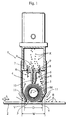
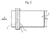
- FIG 1 and Figure 2 are showing an embodiment of a dust removing system according to the present invention, and this dust removing system is possessed with a dust removing head 1, a blower unit (not shown) and a traveler means (not shown) which makes work 2 traverse toward arrow A as the work 2 is arranged to be close to the head 1.
- the dust removing head 1 is comprising an air sucking chamber 4 having an air sucking opening 3 which opens at a position near the work 2, a rotating brushroll 5 disposed inside the air sucking chamber 4 slidable on the work 2, and a nozzle 6 which sucks and removes dust R adhered to the rotating brushroll 5.
- the dust removing head 1 possesses a casing 7 which is long in a width direction of the work 2, and inside the casing 7 the air sucking chamber 4 is formed corresponding to a substantially whole longitudinal length of the casing 7.
- the slit-like air sucking opening 3 having a longitudinal length L longer than a width Wa of the work 2 is formed.
- One end of an air sucking passage not shown in the attached drawings is connected to the air sucking chamber 4, and a blower unit which sucks air in the air sucking chamber 4 is connected to other end of the air sucking passage.
- a blower unit which sucks air in the air sucking chamber 4 is connected to other end of the air sucking passage.
- the rotating brushroll 5 is provided to be rotatable on axis M which is parallel to the slitted air sucking opening 3 inside the air sucking chamber 4 of the casing 7, and the brushroll 5 is rotated by a rotation driving means not shown in the attached drawings toward arrow F in Figure 1. With this rotating brushroll 5, the dust R adhered to a surface of the work 2 is wiped off.
- Nozzle 6 is stuck to an under surface of a partition wall 8 which is provided above the brushroll 5 in the air sucking chamber 4.
- the nozzle 6 has a slit hole 10 extended corresponding to a whole axial length of the brushroll 5.
- the nozzle 6 is possessed with a pair of blade portions 21 having concave face portions 20 which are formed on edges of end portions of outer faces thereof. Tip portions of the blade portions 21 are tip thin portions 22. Between inner faces of the pair of blade portions 21 opposing each other, a slit hole 10 extended corresponding to the whole axial length of the axis M of the brushroll 5 is formed.
- An end of nozzle 6 extended corresponding to the whole axial length of the axis M is arranged to be close to or contact with a circumferential face of the brushroll 5.
- a plurality of air passage slits 9 are provided on the partition wall 8 in the air sucking chamber 4, and one of said air passage slits 9 communicates the slit hole 10 of the nozzle 6.
- a diameter D of the rotating brushroll 5 and an inner width W parallel to a traveling direction of the work 2 of the air sucking chamber 4 are arranged to be D ⁇ W ⁇ (D+20mm). Therefore a space between the rotating brushroll 5 and an inner wall surface of the air sucking chamber 4 is possible to be smaller, and air inside the air sucking chamber 4 can flows at high speed, hereby dust R sucked in the air sucking chamber 4 can quickly flow into the air sucking passage, and the dust R can be prevented not to remain in the air sucking chamber 4, and readhering of the dust R to the work 2 can be also prevented.
- the diameter D and the inner width W are arranged to be (D+3mm) ⁇ W ⁇ (D+10mm), and the air inside the air sucking chamber 4 flows still more smoothly and at higher speed than the case arranged to be D ⁇ W ⁇ (D+20mm), therefore a possibility of the dust R remaining in the air sucking chamber 4 can be prevented.
- D > W the brushroll 5 contacts the inner wall surface of the air sucking chamber 4, and no space exist between the brushroll 5 and the inner wall surface of the air sucking chamber 4. Therefore a velocity of the air flow inside the air sucking chamber 4 is considerably lowered and power of sucking dust R of the dust removing head 1 will lose.
- W > (D+20mm) a space between the brushroll 5 and the inner wall surface of the air sucking chamber 4 becomes too large, and a velocity of the air flow inside the air sucking chamber 4 becomes lower.
- Air passes between divisional walls 11 which form an air sucking opening 3 and a work 2 is arranged to be at a velocity V of 50 to 60 m/s. Therefore dust R is removed from the work 2 still more effectively and is sucked into the air sucking chamber 4 for certain. Furthermore dust R adhered to a work 2 which is difficult to be exfoliated depending on quality of a material of the work 2 by a conventional dust removing system is possible to be removed with the dust removing system of the present invention in some cases.
- a velocity of air flow V is arranged to be below 50 m/s, dust R swept out by the brushroll 5 is possible to go outside through a space between partition walls 11 and a surface of the work 2. Even if a velocity of air flow V is more than 60 m/s, an efficiency of removing dust R does not change very much.
- a rotating brushroll 5 is arranged to rotate within a range of 1600 to 3000 r.p.m.. Therefore dust R adhered to the work 2 is effectively removed and a possibility of the work 2 to be scratched by the brushroll 5 can be prevented. If rotation of the brushroll 5 is below a range of 1600 r.p.m., dust R stuck strongly to the work 2 may not be removed in some cases. If rotation of the brushroll 5 is above a range of 3000 r.p.m., a surface of work 2 is possible to be scratched and damaged by the brushroll 5.
- a length B of bristle end portions 12a among brush bristles 12 of said rotating brushroll 5 contactable to the surface of the work 2 and a thickness T of said work 2 are arranged to be 0 ⁇ B ⁇ T. Therefore while this dust removing system is working, as shown in Figure 5, each of the brush end portions 12a slides surely on the surface of the work 2 in a condition that the brush bristle 12 is slightly bent and is moderately stored elastic energy. For this reason dust adhered to the work 2 is removed still more surely, and the work 2 can be prevented to be damaged. If a length B of the bristle end portion 12a is arranged to be 0 > B, i. e.
- the brushroll 5 will not have a function of removing dust. If B > T, the brush bristle 12 bends largely and hits and scratches the surface of the work 2 hardly.
- dust R adhered to the work 2 is removed surely and efficiently by the rotating brushroll 5 of the present dust removing system. Moreover dust R adhered to the brushroll 5 is removed by applying the nozzle 6, and the dust R adhered to the work 2 again which is removed once from the work 2 is possible to be prevented. Especially, for example, sticky dust, dust stuck in the work 2, fluff of the end rim of the work 2 (in case the work 2 is paper) are removed effectively.
- the dust removing head 1 of the dust removing system can be prevented to be dirty. That is to say, a space between the rotating brushroll 5 and an inner wall surface of an air sucking chamber 4 becomes smaller than that of the conventional dust removing system, and air inside the air sucking chamber 4 flows at high speed and dust R sucked in the air sucking chamber 4 can quickly flow into the air sucking passage. Therefore the dust R is prevented not to remain in the air sucking chamber 4 after an operation of the dust removing system. That is to say, the dust R is prevented not to remain in the rotating brushroll 5 and the inner wall surface of the air sucking chamber 4. Therefore the dust removing head 1 can be used for a long term without cleaning, and a frequency of cleaning and exchanging of the brushroll 5 can be decreased. In consequence, maintenance of the dust removing system would be easy and a running cost would be decreased at the same time.
- the brush bristle 5 can be made of, for example, polyamide resin, acrylic resin, metal, conductive fiber, but it is possible to be made of other materials.
- the work 2 which dust is removed therefrom can be, for example, paper, film or other materials.
- FIG. 6 shows another embodiment of the present invention.
- This dust removing system possesses first and second air discharging chambers 15, 16 arranged on an upstream side H and a downstream side J of an air sucking opening 3 of an air sucking chamber 4 and are provided with first and second ultrasonic nozzles 13, 14 which respectively change air to air knife K including ultrasonic pressure wave P and blow the air knife K against said work 2.
- Divisional walls 11 divide inside a casing 7 of a dust removing head 1 into the air sucking chamber 4 and the first and second discharging chambers 15, 16 on the upstream side H and the downstream side J of said air discharging chamber 4. Structures of rest of parts of this embodiment according to the present invention are almost same as those shown in Figure 1 to 5.
- the first and second air discharging chambers 15, 16 are provided with air from a blower unit not shown in the attached drawings through an air discharging passage not shown in the attached drawings.
- the air passes the first and second ultrasonic nozzle 13, 14, and becomes air knife K including ultrasonic pressure wave P and blown against a work 2. After that the air knife K is sucked in the air sucking chamber 4 together with the dust R, and the air goes back to said blower unit through an air sucking passage.
- an ultrasonic pressure wave P destroys a boundary layer 25 and an air knife K directly hits a surface of a work 2 and dust R can be exfoliated effectively. Therefore two kinds of dust removing operation which are of the brushroll 5 and of the air knife K including the ultrasonic pressure wave P, the dust R adhered to the work 2 can be removed still more surely. Especially, for example, adhesive dust, dust stuck in the work 2, fluff on an end rim of the work 2 (if the work 2 is paper) are removed effectively.
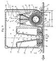
- FIG. 9 shows further embodiment of the present invention.
- the dust removing system possesses an air sucking chamber 17 arranged on a downstream side J of an air sucking chamber 4, and first and second air discharging chambers 15, 16 arranged on the downstream side J of said air sucking chamber 4 and provided with first and second ultrasonic nozzles 13, 14 which blow air knife K including ultrasonic pressure wave P against a work 2 on an upstream side H and a downstream side J of said air sucking chamber 17.
- the air knife K including the ultrasonic pressure wave P blown from the first and second ultrasonic nozzles 13, 14 on the downstream side J of the air sucking chamber 4 is possible to strongly suck and remove dust R remained in the work 2.
- the dust R adhered to the work 2 is removed by two steps of dust removing operations which are operations of the brushroll 5 and the air knife K on the downstream side of the air sucking chamber 4 including the ultrasonic pressure wave P. The dust can be removed still more surely by two steps of the dust removing operation.
- FIG 10 shows still another embodiment of the present invention.
- a casing 7 is possessed with partition walls 11 wherein (for example) blade edge portions 30 having triangular cross sections are obliquely formed on lower end edges thereof (as shown in Figure 10), and a gap between the lower end edge of the partition wall 11 ( i. e. the blade edge portion 30) and (an outer circumferential face of) the brushroll 5 is reduced. Therefore a velocity of air flows in the gap between the lower end edge of the partition wall 11 (i.e. the blade edge portion 30) and the outer circumferential face of the brushroll 5 is increased, and fine dust R separated from the surface of the work 2 can be sucked into the air sucking chamber 4 for certain.
Landscapes
- Cleaning In General (AREA)
- Paper (AREA)
- Coating Apparatus (AREA)
Abstract
Description
- This invention relates to a dust removing system.
- In film industry or paper industry, a dust removing system which can remove adhesive dust, dust stuck in a base member, sticky dust such as feather-like fiber at an edge portion of a base member of, for example, paper or films as well as dust on surface of a base member of such as paper or films is required. In anticipation of an increase of recycled paper hereafter, a problem of paper powder is predicted to be bigger in the paper industry, and a providing of a dust removing system is thought to be unessential.
- A conventional dust removing system for adhesive dust is, as shown in Fig. 11, provided with a
dust removing head 103 comprising a rotatingbrushroll 101 which slides on a traveling work 105 ( a base member) and anair sucking chamber 102 possessing saidbrushroll 101 therein. - However the conventional dust removing system as described above has defects described below.
- ① Because the
air sucking chamber 102 is too big to slow down a velocity of air flow inside theair sucking chamber 102,dust 104 is easy to be collected inside thedust removing head 103, and when the dust removing system is stopped working, thedust 104 falls therefrom and pollutes thework 105 and circumferential systems. - ② Because sucking force of said dust removing system is weak, the
dust 104 adhered to thebrushroll 101 is not removed effectively, and thedust 104 on thebrushroll 101 adheres to thework 105 again. - ③ An air flow of the conventional dust removing system has little dust removing effect, and a bristle of the
brushroll 101 which contacts to thework 105 to removeadhesive dust 104 need to be thick and hard. Consequently thework 105 is possible to be scratched by the bristle. - ④ A force of sucking dust of said conventional dust removing system is basically insufficient (the velocity of air flow is below 10m/s), and dust can not be removed efficiently.
- It is therefore an object of the present invention to provide a dust removing system wherein the foregoing problems are solved and adhesive dust is removed from the work certainly without scratching the work and the dust removing head is prevented to be polluted with dust.
- These objects are solved according to the present invention by a dust removing system including the features of
claims dependent claims 2 to 6. - The present invention will be described with reference to the accompanying drawings, in which:
- Figure 1 is a sectional view of a principal portion of an embodiment of a dust removing system according to the present invention;
- Figure 2 is a schematic top plan view of the dust removing system of Figure 1 under operating situation;
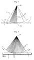
- Figure 3 is an enlarged explanatory view of a principal portion of a function of the dust removing system;
- Figure 4 is an enlarged explanatory view of a principal portion of a function of the dust removing system;
- Figure 5 is an enlarged explanatory view of a principal portion of a function of the dust removing system;
- Figure 6 is a sectional view of a principal portion of another embodiment of the present invention;
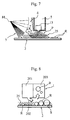
- Figure 7 is an explanatory view of a principal portion of a function of the embodiment of Figure 6;
- Figure 8 is an explanatory view of a function of a comparative example for the present invention;
- Figure 9 is a sectional view of a principal portion of a further embodiment of the present invention;
- Figure 10 is a sectional view of a principal portion of still another embodiment of the present invention; and
- Figure 11 is a sectional view of a principal portion of a conventional dust removing system;
- Preferred embodiments of the present invention will now be described with reference to the accompanying drawings.
- Figure 1 and Figure 2 are showing an embodiment of a dust removing system according to the present invention, and this dust removing system is possessed with a
dust removing head 1, a blower unit (not shown) and a traveler means (not shown) which makeswork 2 traverse toward arrow A as thework 2 is arranged to be close to thehead 1. - The
dust removing head 1 is comprising anair sucking chamber 4 having anair sucking opening 3 which opens at a position near thework 2, a rotatingbrushroll 5 disposed inside theair sucking chamber 4 slidable on thework 2, and anozzle 6 which sucks and removes dust R adhered to the rotatingbrushroll 5. - To be concrete, the
dust removing head 1 possesses acasing 7 which is long in a width direction of thework 2, and inside thecasing 7 theair sucking chamber 4 is formed corresponding to a substantially whole longitudinal length of thecasing 7. On an under surface of thecasing 7, the slit-like air sucking opening 3 having a longitudinal length L longer than a width Wa of thework 2 is formed. ( See Figure 2 ) - One end of an air sucking passage not shown in the attached drawings is connected to the
air sucking chamber 4, and a blower unit which sucks air in theair sucking chamber 4 is connected to other end of the air sucking passage. By sucking force of the blower unit, air inside theair sucking chamber 4 is sucked into the blower unit through the air sucking passage, and air outside the system is sucked through a space between the air sucking opening 3 and thework 2 into theair sucking chamber 4. - As shown in Figure 1, the
rotating brushroll 5 is provided to be rotatable on axis M which is parallel to the slitted air sucking opening 3 inside theair sucking chamber 4 of thecasing 7, and thebrushroll 5 is rotated by a rotation driving means not shown in the attached drawings toward arrow F in Figure 1. With thisrotating brushroll 5, the dust R adhered to a surface of thework 2 is wiped off. -
Nozzle 6 is stuck to an under surface of apartition wall 8 which is provided above thebrushroll 5 in theair sucking chamber 4. Thenozzle 6 has aslit hole 10 extended corresponding to a whole axial length of thebrushroll 5. Specifically, as shown in Figure 3, thenozzle 6 is possessed with a pair ofblade portions 21 havingconcave face portions 20 which are formed on edges of end portions of outer faces thereof. Tip portions of theblade portions 21 are tipthin portions 22. Between inner faces of the pair ofblade portions 21 opposing each other, aslit hole 10 extended corresponding to the whole axial length of the axis M of thebrushroll 5 is formed. An end ofnozzle 6 extended corresponding to the whole axial length of the axis M is arranged to be close to or contact with a circumferential face of thebrushroll 5. A plurality ofair passage slits 9 are provided on thepartition wall 8 in theair sucking chamber 4, and one of saidair passage slits 9 communicates theslit hole 10 of thenozzle 6. - As the present invention is constructed above, when air is sucked from the
slit hole 10 of thenozzle 6 toward arrow C, air around theconcave face portions 20 of the end portion of thenozzle 6 flows at high speed downwardly along theconcave face portions 20 as broken lines show in Figure 3, and the air reaches at a slightly deep position of thebrush bristle 12 before sucked into theslit hole 10. Therefore dust R adhered to thebrush bristle 12 of the rotatingbrushroll 5 can be completely removed. - Next, referring back to Figure 1, a diameter D of the rotating
brushroll 5 and an inner width W parallel to a traveling direction of thework 2 of theair sucking chamber 4 are arranged to be D≦ W≦ (D+20mm). Therefore a space between the rotatingbrushroll 5 and an inner wall surface of theair sucking chamber 4 is possible to be smaller, and air inside theair sucking chamber 4 can flows at high speed, hereby dust R sucked in theair sucking chamber 4 can quickly flow into the air sucking passage, and the dust R can be prevented not to remain in theair sucking chamber 4, and readhering of the dust R to thework 2 can be also prevented. - Further preferably, the diameter D and the inner width W are arranged to be (D+3mm) ≦ W≦ (D+10mm), and the air inside the
air sucking chamber 4 flows still more smoothly and at higher speed than the case arranged to be D≦ W≦ (D+20mm), therefore a possibility of the dust R remaining in theair sucking chamber 4 can be prevented. If D > W, thebrushroll 5 contacts the inner wall surface of theair sucking chamber 4, and no space exist between thebrushroll 5 and the inner wall surface of theair sucking chamber 4. Therefore a velocity of the air flow inside theair sucking chamber 4 is considerably lowered and power of sucking dust R of thedust removing head 1 will lose. If W > (D+20mm), a space between thebrushroll 5 and the inner wall surface of theair sucking chamber 4 becomes too large, and a velocity of the air flow inside theair sucking chamber 4 becomes lower. - Air passes between
divisional walls 11 which form an air sucking opening 3 and awork 2 is arranged to be at a velocity V of 50 to 60 m/s. Therefore dust R is removed from thework 2 still more effectively and is sucked into theair sucking chamber 4 for certain. Furthermore dust R adhered to awork 2 which is difficult to be exfoliated depending on quality of a material of thework 2 by a conventional dust removing system is possible to be removed with the dust removing system of the present invention in some cases. When a velocity of air flow V is arranged to be below 50 m/s, dust R swept out by thebrushroll 5 is possible to go outside through a space betweenpartition walls 11 and a surface of thework 2. Even if a velocity of air flow V is more than 60 m/s, an efficiency of removing dust R does not change very much. - A rotating
brushroll 5 is arranged to rotate within a range of 1600 to 3000 r.p.m.. Therefore dust R adhered to thework 2 is effectively removed and a possibility of thework 2 to be scratched by thebrushroll 5 can be prevented. If rotation of thebrushroll 5 is below a range of 1600 r.p.m., dust R stuck strongly to thework 2 may not be removed in some cases. If rotation of thebrushroll 5 is above a range of 3000 r.p.m., a surface ofwork 2 is possible to be scratched and damaged by thebrushroll 5. - As shown in Figure 4, a length B of
bristle end portions 12a amongbrush bristles 12 of said rotatingbrushroll 5 contactable to the surface of thework 2 and a thickness T of saidwork 2 are arranged to be 0≦ B≦ T. Therefore while this dust removing system is working, as shown in Figure 5, each of thebrush end portions 12a slides surely on the surface of thework 2 in a condition that thebrush bristle 12 is slightly bent and is moderately stored elastic energy. For this reason dust adhered to thework 2 is removed still more surely, and thework 2 can be prevented to be damaged. If a length B of thebristle end portion 12a is arranged to be 0 > B, i. e. if thebristle end portion 12a is arranged not to touch the surface of thework 2, thebrushroll 5 will not have a function of removing dust. If B > T, thebrush bristle 12 bends largely and hits and scratches the surface of thework 2 hardly. - As the present invention is described in the foregoing, dust R adhered to the
work 2 is removed surely and efficiently by the rotatingbrushroll 5 of the present dust removing system. Moreover dust R adhered to thebrushroll 5 is removed by applying thenozzle 6, and the dust R adhered to thework 2 again which is removed once from thework 2 is possible to be prevented. Especially, for example, sticky dust, dust stuck in thework 2, fluff of the end rim of the work 2 (in case thework 2 is paper) are removed effectively. - The
dust removing head 1 of the dust removing system can be prevented to be dirty. That is to say, a space between therotating brushroll 5 and an inner wall surface of anair sucking chamber 4 becomes smaller than that of the conventional dust removing system, and air inside theair sucking chamber 4 flows at high speed and dust R sucked in theair sucking chamber 4 can quickly flow into the air sucking passage. Therefore the dust R is prevented not to remain in theair sucking chamber 4 after an operation of the dust removing system. That is to say, the dust R is prevented not to remain in therotating brushroll 5 and the inner wall surface of theair sucking chamber 4. Therefore thedust removing head 1 can be used for a long term without cleaning, and a frequency of cleaning and exchanging of thebrushroll 5 can be decreased. In consequence, maintenance of the dust removing system would be easy and a running cost would be decreased at the same time. - The brush bristle 5 can be made of, for example, polyamide resin, acrylic resin, metal, conductive fiber, but it is possible to be made of other materials. The
work 2 which dust is removed therefrom can be, for example, paper, film or other materials. - Next, Figure 6 shows another embodiment of the present invention. This dust removing system possesses first and second
air discharging chambers air sucking opening 3 of anair sucking chamber 4 and are provided with first and secondultrasonic nozzles work 2. -
Divisional walls 11 divide inside acasing 7 of adust removing head 1 into theair sucking chamber 4 and the first and second dischargingchambers air discharging chamber 4. Structures of rest of parts of this embodiment according to the present invention are almost same as those shown in Figure 1 to 5. - The first and second
air discharging chambers ultrasonic nozzle work 2. After that the air knife K is sucked in theair sucking chamber 4 together with the dust R, and the air goes back to said blower unit through an air sucking passage. - Referring to Figure 8, when air which simply blows at a high speed is arranged to blow from an
air discharging chamber 201 against a surface of awork 2 and is arranged to be sucked into anair sucking chamber 203, a part of dust R is separated from a surface of thework 2 by, so called, an air knife operation of the air flow, however aboundary layer 25 where air flows at a low speed therein is formed over the surface of thework 2, and most of the dust R is shut in saidboundary layer 25, therefore the removing dust R from thework 2 becomes difficult. - With the dust removing system of the present invention as shown in Figure 7, an ultrasonic pressure wave P destroys a
boundary layer 25 and an air knife K directly hits a surface of awork 2 and dust R can be exfoliated effectively. Therefore two kinds of dust removing operation which are of thebrushroll 5 and of the air knife K including the ultrasonic pressure wave P, the dust R adhered to thework 2 can be removed still more surely. Especially, for example, adhesive dust, dust stuck in thework 2, fluff on an end rim of the work 2 (if thework 2 is paper) are removed effectively. - Figure 9 shows further embodiment of the present invention. The dust removing system possesses an
air sucking chamber 17 arranged on a downstream side J of anair sucking chamber 4, and first and secondair discharging chambers air sucking chamber 4 and provided with first and secondultrasonic nozzles work 2 on an upstream side H and a downstream side J of saidair sucking chamber 17. - Therefore inside a
casing 7 of thedust removing head 1, theair sucking chamber 4, theair sucking chamber 17 possessing anair sucking opening 19 which opens downwardly at the downstream side J of theair sucking chamber 4, a communicatingchamber 18 communicating both theair sucking chambers air discharging chambers - As the present invention is constructed as described above, after exfoliated adhesive dust R stuck to the
work 2 with thebrushroll 5 in theair sucking chamber 4 on the upstream side H of theair sucking chamber 4, the air knife K including the ultrasonic pressure wave P blown from the first and secondultrasonic nozzles air sucking chamber 4 is possible to strongly suck and remove dust R remained in thework 2. The dust R adhered to thework 2 is removed by two steps of dust removing operations which are operations of thebrushroll 5 and the air knife K on the downstream side of theair sucking chamber 4 including the ultrasonic pressure wave P. The dust can be removed still more surely by two steps of the dust removing operation. - Figure 10 shows still another embodiment of the present invention. A
casing 7 is possessed withpartition walls 11 wherein (for example)blade edge portions 30 having triangular cross sections are obliquely formed on lower end edges thereof (as shown in Figure 10), and a gap between the lower end edge of the partition wall 11 ( i. e. the blade edge portion 30) and (an outer circumferential face of) thebrushroll 5 is reduced. Therefore a velocity of air flows in the gap between the lower end edge of the partition wall 11 (i.e. the blade edge portion 30) and the outer circumferential face of thebrushroll 5 is increased, and fine dust R separated from the surface of thework 2 can be sucked into theair sucking chamber 4 for certain. - While preferred embodiments of the present invention have been described in this specification, it is to be understood that the invention is illustrative and not restrictive, because various changes are possible within the spirit and indispensable features.
Claims (9)
- A dust removing system characterized by:an air sucking chamber (4) having an air sucking opening (3) which opens at a position near a work (2);a rotating brushroll (5) arranged inside said air sucking chamber (4) slidable on said work (2); anda nozzle (6) arranged inside said air sucking chamber (4) for sucking and removing dust (R) adhering to the rotating brushroll (5) arranged to be close to or contact with said rotating brushroll (5).
- The dust removing system as set forth in claim 1, characterized in that a diameter (D) of said rotating brushroll (5) and an inner width (W) of said air sucking chamber (4) parallel to a traveling direction of said work (2) are arranged to be D ≦ W≦ (D+20mm).
- The dust removing system as set forth in claim 1, characterized in that a diameter (D) of said rotating brushroll (5) and an inner width (W) of said air sucking chamber (4) parallel to a traveling direction of said work (2) are arranged to be (D+3mm) ≦ W≦ (D+10mm).
- The dust removing system as set forth in claim 1, characterized in that a longitudinal length (B) of bristle end portions (12a) among brush bristles (12) of said rotating brush roll (5) contactable to a surface of said work (2) and a thickness (T) of said work (2) are arranged to be 0 ≦ B≦ T.
- The dust removing system as set forth in claim 1, characterized in that a longitudinal length (B) of bristle end portions (12a) among brush bristles (12) of said rotating brush roll (5) contactable to a surface of said work (2) and a thickness (T) of said work (2) are arranged to be 0 ≦ B≦ T, and said rotating brush roll (5) is arranged to rotate within a range of 1600 to 3000 r.p.m..
- The dust removing system as set forth in claim 1, characterized in that air passes between a divisional wall (11) and a surface of said work (2) forming an air sucking opening (3) at a velocity (V) of 50 to 60 m/s.
- A dust removing system characterized in that:an air sucking chamber (4) is provided with a rotating brushrol (5) which slides on a work (2) and a nozzle (6) for sucking and removing dust (R) adhering to the rotating brushroll (5) arranged to be close to or contact with said rotating brushroll (5); andfirst and second air discharging chambers (15), (16) are arranged on an upstream side (H) and a downstream side (J) of an air sucking opening (3) of said air sucking chamber (4) and are provided with first and second ultrasonic nozzles (13), (14) which respectively change air to air knife (K) including ultrasonic pressure wave (P) and blow the air knife (K) against said work (2).
- A dust removing system characterized by:an air sucking chamber (4) having an air sucking opening (3) which opens at a position near a work (2);a rotating brushroll (5) arranged inside said air sucking chamber (4) slidable on said work (2);a nozzle (6) for sucking and removing dust (R) adhering to the rotating brushroll (5) arranged inside said air sucking chamber (4) and to be close to or contact with said rotating brushroll (5);an air sucking chamber (17) arranged on a downstream side (J) of said air sucking chamber (4); andfirst and second air discharging chambers (15), (16) arranged on a downstream side (J) of said air sucking chamber (4) and provided with first and second ultrasonic nozzles (13), (14) which blow air knife (K) including ultrasonic pressure wave (P) against a work (2) on an upstream side (H) and a downstream side (I) of said air sucking chamber (17).
- A dust removing system characterized by:an air sucking chamber (4) having an air sucking opening (3) which opens at a position near a work (2);a rotating brushroll (5) arranged inside said air sucking chamber (4) slidable on said work (2);a nozzle (6) which is arranged inside said air sucking chamber (4) for sucking and removing dust (R) adhering to the rotating brushroll (5), arranged to be close to or contact with said rotating brushroll (5), and provided with a pair of blade portions (21) respectively possessing concave face portion (20) on a tip end portion of an outer face thereof and a slit hole (10) formed between inner faces of said blade portions (21) opposite each other and extended corresponding to a whole axial length of the brushroll (5).
Applications Claiming Priority (3)
| Application Number | Priority Date | Filing Date | Title |
|---|---|---|---|
| JP159057/96 | 1996-05-29 | ||
| JP08159057A JP3122370B2 (en) | 1996-05-29 | 1996-05-29 | Dust removal device |
| JP15905796 | 1996-05-29 |
Publications (3)
| Publication Number | Publication Date |
|---|---|
| EP0810039A2 true EP0810039A2 (en) | 1997-12-03 |
| EP0810039A3 EP0810039A3 (en) | 1998-11-04 |
| EP0810039B1 EP0810039B1 (en) | 2002-01-23 |
Family
ID=15685286
Family Applications (1)
| Application Number | Title | Priority Date | Filing Date |
|---|---|---|---|
| EP97108466A Expired - Lifetime EP0810039B1 (en) | 1996-05-29 | 1997-05-26 | Dust removing system |
Country Status (6)
| Country | Link |
|---|---|
| EP (1) | EP0810039B1 (en) |
| JP (1) | JP3122370B2 (en) |
| KR (1) | KR100267630B1 (en) |
| CN (1) | CN1182925C (en) |
| DE (1) | DE69709984T2 (en) |
| TW (1) | TW327140B (en) |
Cited By (23)
| Publication number | Priority date | Publication date | Assignee | Title |
|---|---|---|---|---|
| DE19838757C1 (en) * | 1998-08-26 | 1999-12-30 | Abb Patent Gmbh | Method of cleaning vehicle factory workpiece carrier |
| DE10018388C1 (en) * | 2000-04-13 | 2002-01-03 | Airbus Gmbh | Device, for cleaning surface of component, especially near connecting element, has brush arrangement with at least one rotating brush connected by transmission elements to air turbine and suction unit |
| DE10302127A1 (en) * | 2002-01-21 | 2003-11-20 | Honda Motor Co Ltd | Dust removal device |
| WO2005049238A1 (en) * | 2003-11-21 | 2005-06-02 | Nix, Inc. | Dust extractor and dust extracting method |
| WO2007059919A3 (en) * | 2005-11-22 | 2007-11-29 | Robo Paper B V | Device and method for cleaning a rotating material strip |
| EP2037037A1 (en) * | 2007-08-13 | 2009-03-18 | Equitan S.r.l. | Device for removing residual objects from a surface of a thin, flexible layer |
| FR2931712A1 (en) * | 2008-06-02 | 2009-12-04 | Bosch Gmbh Robert | MOTORIZED DEVICE FOR CLEANING AT LEAST ONE CRUSHER OF A SOLDERING PLANT |
| WO2010140967A1 (en) * | 2009-06-03 | 2010-12-09 | Leif Yxfeldt | Method and device for treating surfaces |
| CN102319712A (en) * | 2011-08-01 | 2012-01-18 | 广东润成创展木业有限公司 | Environmentally-friendly dust precipitation chamber for painting wood door |
| CN105935660A (en) * | 2016-06-30 | 2016-09-14 | 务川务欣米业有限责任公司 | Rice dust removing and classifying system set |
| EP3626356A1 (en) * | 2018-09-18 | 2020-03-25 | Kabushiki Kaisha Toshiba | Cleaner head, removing apparatus, and removing method |
| CN111335009A (en) * | 2020-03-31 | 2020-06-26 | 天翊(江门)智能装备有限公司 | Full-automatic cloth dust collecting equipment |
| CN112845207A (en) * | 2020-12-23 | 2021-05-28 | 海南红塔卷烟有限责任公司 | Labeling machine for upper and lower surfaces of non-standard paper box |
| EP3686324A4 (en) * | 2017-09-20 | 2021-07-07 | Kabushiki Kaisha Toshiba | SPINNING DEVICE |
| CN113275289A (en) * | 2021-06-10 | 2021-08-20 | 吴新茂 | Energy-saving auto radiator cleaning device |
| US11141759B2 (en) | 2017-06-13 | 2021-10-12 | Hymmen GmbH Maschinen- und Anlagesbas | Method and apparatus for producing a decorative surface |
| CN113908936A (en) * | 2021-10-11 | 2022-01-11 | 常州智砼绿色建筑科技有限公司 | A crusher for construction waste |
| CN114643217A (en) * | 2022-03-21 | 2022-06-21 | 马鞍山市粤美金属制品科技实业有限公司 | Compressor bearing assembly detection device |
| US11559824B2 (en) | 2019-05-03 | 2023-01-24 | Hymmen Gmbh Maschinen-Und Anlagenbau | Method for producing a structure on a surface |
| CN116618401A (en) * | 2023-06-20 | 2023-08-22 | 重庆两江联创电子有限公司 | A CG cleaning device |
| GB2618595A (en) * | 2022-05-12 | 2023-11-15 | Meech Static Eliminators Ltd | Apparatus and method for web cleaning |
| WO2024112192A1 (en) * | 2022-11-22 | 2024-05-30 | Besi Netherlands B.V. | Cleaning unit for a mould for encapsulating electronic components, moulding system and method for encapsulating electronic components |
| WO2024188891A1 (en) * | 2023-03-10 | 2024-09-19 | Wandres Gmbh Micro-Cleaning | Cleaning device, method for cleaning, and use of a cleaning device for fast-running surfaces |
Families Citing this family (30)
| Publication number | Priority date | Publication date | Assignee | Title |
|---|---|---|---|---|
| ATE439195T1 (en) * | 2004-09-17 | 2009-08-15 | Synergetics Proprietary Ltd | DEVICE AND METHOD FOR REMOVAL OF DUST |
| DE102007028341A1 (en) | 2007-06-15 | 2008-12-18 | Robo Paper B.V. | Device and method for cleaning a revolving web element |
| JP5310117B2 (en) * | 2009-03-06 | 2013-10-09 | 王子ホールディングス株式会社 | Dust remover |
| WO2011039972A1 (en) * | 2009-10-02 | 2011-04-07 | シャープ株式会社 | Cleaning nozzle and dust removal device equipped with same |
| DE102010054813B4 (en) * | 2010-12-16 | 2012-07-26 | Karl W. Niemann Gmbh & Co. Kg | Method and device for laminating a substrate plate with a plastic film |
| NL2007110C2 (en) * | 2011-07-14 | 2013-01-15 | Fico Bv | DEVICE FOR CLEANING AN ENCLOSURE DEVICE FOR ELECTRONIC COMPONENTS. |
| CN102715874A (en) * | 2012-06-07 | 2012-10-10 | 杜爵伟 | Floor cleaner |
| CN202725553U (en) * | 2012-07-09 | 2013-02-13 | 深圳市华星光电技术有限公司 | Cleaning device |
| JP6058312B2 (en) * | 2012-08-06 | 2017-01-11 | ヒューグル開発株式会社 | Cleaning head |
| CN103100538A (en) * | 2012-12-13 | 2013-05-15 | 吴江忆久纺织有限公司 | Dust exhaust device used for textile workshop |
| CN103272817B (en) * | 2013-05-29 | 2015-09-02 | 广东东睦新材料有限公司 | A kind of dust collector for powder metallurgy |
| CN103521479B (en) | 2013-09-27 | 2016-03-30 | 京东方科技集团股份有限公司 | Cleaning device and linear coater |
| CN104148306A (en) * | 2014-07-30 | 2014-11-19 | 熊丹 | Solar cell dust removal equipment |
| CN105032841B (en) * | 2015-07-23 | 2017-07-14 | 熊一凡 | High pressure draught hand for clearing up harmful dust |
| CN105149250A (en) * | 2015-09-08 | 2015-12-16 | 宁国市南方耐磨材料有限公司 | Spherical wear-resistant steel ball impurity removal device |
| CN105834137B (en) * | 2016-05-31 | 2018-03-16 | 圣象实业(江苏)有限公司 | Floor dedusting cleaning device |
| CN107282488A (en) * | 2017-07-18 | 2017-10-24 | 合肥余塝电子商务有限公司 | A kind of electronic apparatus is classified dust arrester |
| CN107874704B (en) * | 2017-12-05 | 2023-08-15 | 江苏美的清洁电器股份有限公司 | Scraper, floor brush with the scraper, and vacuum cleaner with the floor brush |
| CN109331574B (en) * | 2018-11-27 | 2021-06-18 | 西安科技大学 | Exhaust and dust removal equipment and method suitable for gas dust explosion closed container |
| CN110077883B (en) * | 2019-04-19 | 2020-09-08 | 浙江常鑫纺织品有限公司 | Clothing auxiliary material design finishing device |
| CN109877469B (en) * | 2019-04-26 | 2020-11-20 | 郑微丹 | Dust removal mechanism for laser cutting |
| CN110624867B (en) * | 2019-10-23 | 2021-08-06 | 郑州财经学院 | Cleaning device of brush roller for spinning |
| CN112170310A (en) * | 2020-09-15 | 2021-01-05 | 国网山东省电力公司平阴县供电公司 | Cabinet dust collector |
| JP7612376B2 (en) * | 2020-10-26 | 2025-01-14 | 株式会社東芝 | Electrospinning apparatus and method for cleaning electrospinning head |
| CN112452928A (en) * | 2020-11-02 | 2021-03-09 | 王宝根 | Automatic dust collector of silicon chip |
| CN112547621B (en) * | 2020-11-20 | 2022-04-19 | 贵州黔北粮仓米业有限公司 | Intelligent rice processing equipment |
| KR102578251B1 (en) * | 2021-02-10 | 2023-09-13 | (주)필옵틱스 | Cleaning device for the work table |
| CN113154862B (en) * | 2021-02-26 | 2022-07-15 | 东莞汇和电子有限公司 | An electronic circuit board assembly piston drying air knife |
| CN114542416B (en) * | 2022-02-23 | 2023-10-27 | 吴小龙 | Belt air compressor with antifouling function |
| CN117019772B (en) * | 2023-10-08 | 2024-02-23 | 宁德时代新能源科技股份有限公司 | Dust removal mechanism, pole piece dust removal device and battery production system |
Family Cites Families (10)
| Publication number | Priority date | Publication date | Assignee | Title |
|---|---|---|---|---|
| US3986223A (en) * | 1973-05-21 | 1976-10-19 | Herbert Products, Inc. | Surface cleaning device |
| US4282626A (en) * | 1977-10-17 | 1981-08-11 | California Institute Of Technology | Cleaning devices |
| CH654753A5 (en) * | 1982-01-21 | 1986-03-14 | Fredy Truniger | Method and apparatus for cleaning the outside of an approximately cylindrical filter element |
| US4706325A (en) * | 1986-07-09 | 1987-11-17 | Michelson Manfred G | Film cleaner |
| JPH0636906B2 (en) * | 1988-05-11 | 1994-05-18 | 株式会社伸興 | Dust remover |
| EP0356795A3 (en) * | 1988-08-23 | 1991-12-18 | Maschinenfabrik Rieter Ag | Cleaning apparatus for the wandering flats of a carding machine |
| JPH06102128B2 (en) * | 1991-08-12 | 1994-12-14 | 株式会社整電社 | Filter cleaning equipment |
| JP2567191Y2 (en) * | 1992-04-13 | 1998-03-30 | 株式会社伸興 | Panel body dust remover |
| JP2820599B2 (en) * | 1993-08-31 | 1998-11-05 | 株式会社伸興 | Dust removal device |
| FI95611C (en) * | 1994-05-16 | 1996-02-26 | Valmet Paper Machinery Inc | Method and apparatus on a paper machine or finishing apparatus for such to collect and remove dust discharging from the web |
-
1996
- 1996-05-29 JP JP08159057A patent/JP3122370B2/en not_active Expired - Lifetime
-
1997
- 1997-05-12 TW TW086106280A patent/TW327140B/en not_active IP Right Cessation
- 1997-05-26 EP EP97108466A patent/EP0810039B1/en not_active Expired - Lifetime
- 1997-05-26 DE DE69709984T patent/DE69709984T2/en not_active Expired - Lifetime
- 1997-05-29 CN CNB971054193A patent/CN1182925C/en not_active Expired - Lifetime
- 1997-05-29 KR KR1019970021488A patent/KR100267630B1/en not_active Expired - Lifetime
Cited By (37)
| Publication number | Priority date | Publication date | Assignee | Title |
|---|---|---|---|---|
| DE19838757C1 (en) * | 1998-08-26 | 1999-12-30 | Abb Patent Gmbh | Method of cleaning vehicle factory workpiece carrier |
| DE10018388C1 (en) * | 2000-04-13 | 2002-01-03 | Airbus Gmbh | Device, for cleaning surface of component, especially near connecting element, has brush arrangement with at least one rotating brush connected by transmission elements to air turbine and suction unit |
| DE10302127A1 (en) * | 2002-01-21 | 2003-11-20 | Honda Motor Co Ltd | Dust removal device |
| US7017226B2 (en) | 2002-01-21 | 2006-03-28 | Honda Giken Kogyo Kabushiki Kaisha | Dust removal apparatus |
| WO2005049238A1 (en) * | 2003-11-21 | 2005-06-02 | Nix, Inc. | Dust extractor and dust extracting method |
| WO2007059919A3 (en) * | 2005-11-22 | 2007-11-29 | Robo Paper B V | Device and method for cleaning a rotating material strip |
| EP2037037A1 (en) * | 2007-08-13 | 2009-03-18 | Equitan S.r.l. | Device for removing residual objects from a surface of a thin, flexible layer |
| FR2931712A1 (en) * | 2008-06-02 | 2009-12-04 | Bosch Gmbh Robert | MOTORIZED DEVICE FOR CLEANING AT LEAST ONE CRUSHER OF A SOLDERING PLANT |
| EP2130613A1 (en) * | 2008-06-02 | 2009-12-09 | Robert Bosch GmbH | Motorised device for cleaning at least one crucible of a brazing installation |
| WO2010140967A1 (en) * | 2009-06-03 | 2010-12-09 | Leif Yxfeldt | Method and device for treating surfaces |
| CN102458696A (en) * | 2009-06-03 | 2012-05-16 | L·伊西费尔特 | Method and apparatus for treating surfaces |
| CN102319712A (en) * | 2011-08-01 | 2012-01-18 | 广东润成创展木业有限公司 | Environmentally-friendly dust precipitation chamber for painting wood door |
| CN105935660A (en) * | 2016-06-30 | 2016-09-14 | 务川务欣米业有限责任公司 | Rice dust removing and classifying system set |
| CN105935660B (en) * | 2016-06-30 | 2018-05-22 | 务川务欣米业有限责任公司 | A set of rice dedusting hierarchy system |
| US11717850B2 (en) | 2017-06-13 | 2023-08-08 | Hymmen Gmbh Maschinen-Und Anlagenbau | Method and apparatus for producing a decorative workpiece and workpiece |
| US12090511B2 (en) | 2017-06-13 | 2024-09-17 | Hymmen GmbH Maschinen—und Anlagenbau | Method and apparatus for producing a decorative surface |
| US11141759B2 (en) | 2017-06-13 | 2021-10-12 | Hymmen GmbH Maschinen- und Anlagesbas | Method and apparatus for producing a decorative surface |
| US11717851B2 (en) | 2017-06-13 | 2023-08-08 | Hymmen GmbH Maschinen—und Anlagenbau | Method and apparatus for producing a decorative workpiece and workpiece |
| US12194492B2 (en) | 2017-06-13 | 2025-01-14 | Hymmen GmbH Maschinen- und Anlagenbau | Digital printing apparatus and a digital method for producing a structured surface |
| US11420229B2 (en) | 2017-06-13 | 2022-08-23 | Hymmen GmbH Maschinen—und Anlagenbau | Method and apparatus for producing a decorative surface |
| US11511318B2 (en) | 2017-06-13 | 2022-11-29 | Hymmen GmbH Maschinen- und Anlagenbau | Method and apparatus for producing a decorative workpiece and workpiece |
| US11883843B2 (en) | 2017-06-13 | 2024-01-30 | Hymmen Gmbh Maschinen-Und Anlagenbau | Method for producing a structured surface |
| EP3686324A4 (en) * | 2017-09-20 | 2021-07-07 | Kabushiki Kaisha Toshiba | SPINNING DEVICE |
| US11559134B2 (en) | 2018-09-18 | 2023-01-24 | Kabushiki Kaisha Toshiba | Cleaner head, removing apparatus, and removing method |
| EP3626356A1 (en) * | 2018-09-18 | 2020-03-25 | Kabushiki Kaisha Toshiba | Cleaner head, removing apparatus, and removing method |
| US11559824B2 (en) | 2019-05-03 | 2023-01-24 | Hymmen Gmbh Maschinen-Und Anlagenbau | Method for producing a structure on a surface |
| CN111335009A (en) * | 2020-03-31 | 2020-06-26 | 天翊(江门)智能装备有限公司 | Full-automatic cloth dust collecting equipment |
| CN112845207A (en) * | 2020-12-23 | 2021-05-28 | 海南红塔卷烟有限责任公司 | Labeling machine for upper and lower surfaces of non-standard paper box |
| CN113275289A (en) * | 2021-06-10 | 2021-08-20 | 吴新茂 | Energy-saving auto radiator cleaning device |
| CN113908936A (en) * | 2021-10-11 | 2022-01-11 | 常州智砼绿色建筑科技有限公司 | A crusher for construction waste |
| CN114643217A (en) * | 2022-03-21 | 2022-06-21 | 马鞍山市粤美金属制品科技实业有限公司 | Compressor bearing assembly detection device |
| WO2023218173A1 (en) * | 2022-05-12 | 2023-11-16 | Meech Static Eliminators Limited | Apparatus and method for web cleaning |
| GB2618595A (en) * | 2022-05-12 | 2023-11-15 | Meech Static Eliminators Ltd | Apparatus and method for web cleaning |
| WO2024112192A1 (en) * | 2022-11-22 | 2024-05-30 | Besi Netherlands B.V. | Cleaning unit for a mould for encapsulating electronic components, moulding system and method for encapsulating electronic components |
| NL2033591B1 (en) * | 2022-11-22 | 2024-05-30 | Besi Netherlands Bv | Cleaning unit for a mould for encapsulating electronic components, moulding system and method for encapsulating electronic components |
| WO2024188891A1 (en) * | 2023-03-10 | 2024-09-19 | Wandres Gmbh Micro-Cleaning | Cleaning device, method for cleaning, and use of a cleaning device for fast-running surfaces |
| CN116618401A (en) * | 2023-06-20 | 2023-08-22 | 重庆两江联创电子有限公司 | A CG cleaning device |
Also Published As
| Publication number | Publication date |
|---|---|
| DE69709984T2 (en) | 2002-09-26 |
| JP3122370B2 (en) | 2001-01-09 |
| CN1182925C (en) | 2005-01-05 |
| KR100267630B1 (en) | 2000-10-16 |
| EP0810039A3 (en) | 1998-11-04 |
| DE69709984D1 (en) | 2002-03-14 |
| EP0810039B1 (en) | 2002-01-23 |
| KR970073747A (en) | 1997-12-10 |
| CN1166386A (en) | 1997-12-03 |
| JPH09314072A (en) | 1997-12-09 |
| TW327140B (en) | 1998-02-21 |
Similar Documents
| Publication | Publication Date | Title |
|---|---|---|
| EP0810039A2 (en) | Dust removing system | |
| US5466298A (en) | Web cleaning method | |
| KR100267473B1 (en) | Apparatus for cleaning objects in movement | |
| US20090165238A1 (en) | Web substrate cleaning systems & methods | |
| US3239863A (en) | Pressure gradient web cleaning apparatus | |
| EP0139211B1 (en) | Suction nozzle | |
| US7147724B2 (en) | Cleaning device for a longitudinal cutting device and method for cleaning the device | |
| CN1113170A (en) | Contactless sealing unit for seam of discharging part of frame of rolling machine | |
| US5241908A (en) | Washing device of a printing device | |
| US3436265A (en) | Pressure gradient web cleaning method | |
| JP2001038880A (en) | Dust removing apparatus for corrugated board paper printing machine | |
| JP3400675B2 (en) | Dust removal device | |
| JPH01299682A (en) | Method for removing dust from web | |
| CN110062667A (en) | Contact fur brush cleaner | |
| JP5310117B2 (en) | Dust remover | |
| JP3601461B2 (en) | Work adhering matter removal device | |
| JP3211788U (en) | Steel plate cleaning device | |
| WO2023218173A1 (en) | Apparatus and method for web cleaning | |
| GB2172014A (en) | Process and apparatus for removing a film of material clinging to moving strip material | |
| JP3655994B2 (en) | Dust removal equipment | |
| JPH0820112A (en) | Ink jet recording apparatus | |
| CN223556713U (en) | A circuit board cleaning device | |
| CN102039613B (en) | Dust-removing device | |
| JPH06165960A (en) | Suction nozzle, ultrasonic dust removing nozzle and ultrasonic dust removing device | |
| JPH06115057A (en) | Cylinder cleaning device |
Legal Events
| Date | Code | Title | Description |
|---|---|---|---|
| PUAI | Public reference made under article 153(3) epc to a published international application that has entered the european phase |
Free format text: ORIGINAL CODE: 0009012 |
|
| AK | Designated contracting states |
Kind code of ref document: A2 Designated state(s): DE FR GB IT |
|
| PUAL | Search report despatched |
Free format text: ORIGINAL CODE: 0009013 |
|
| AK | Designated contracting states |
Kind code of ref document: A3 Designated state(s): DE FR GB IT |
|
| 17P | Request for examination filed |
Effective date: 19981223 |
|
| 17Q | First examination report despatched |
Effective date: 20000608 |
|
| GRAG | Despatch of communication of intention to grant |
Free format text: ORIGINAL CODE: EPIDOS AGRA |
|
| GRAG | Despatch of communication of intention to grant |
Free format text: ORIGINAL CODE: EPIDOS AGRA |
|
| GRAH | Despatch of communication of intention to grant a patent |
Free format text: ORIGINAL CODE: EPIDOS IGRA |
|
| GRAH | Despatch of communication of intention to grant a patent |
Free format text: ORIGINAL CODE: EPIDOS IGRA |
|
| GRAA | (expected) grant |
Free format text: ORIGINAL CODE: 0009210 |
|
| REG | Reference to a national code |
Ref country code: GB Ref legal event code: IF02 |
|
| AK | Designated contracting states |
Kind code of ref document: B1 Designated state(s): DE FR GB IT |
|
| REF | Corresponds to: |
Ref document number: 69709984 Country of ref document: DE Date of ref document: 20020314 |
|
| ET | Fr: translation filed | ||
| PLBE | No opposition filed within time limit |
Free format text: ORIGINAL CODE: 0009261 |
|
| STAA | Information on the status of an ep patent application or granted ep patent |
Free format text: STATUS: NO OPPOSITION FILED WITHIN TIME LIMIT |
|
| 26N | No opposition filed | ||
| REG | Reference to a national code |
Ref country code: FR Ref legal event code: PLFP Year of fee payment: 20 |
|
| PGFP | Annual fee paid to national office [announced via postgrant information from national office to epo] |
Ref country code: DE Payment date: 20160523 Year of fee payment: 20 Ref country code: GB Payment date: 20160504 Year of fee payment: 20 |
|
| PGFP | Annual fee paid to national office [announced via postgrant information from national office to epo] |
Ref country code: FR Payment date: 20160429 Year of fee payment: 20 Ref country code: IT Payment date: 20160520 Year of fee payment: 20 |
|
| REG | Reference to a national code |
Ref country code: DE Ref legal event code: R071 Ref document number: 69709984 Country of ref document: DE |
|
| REG | Reference to a national code |
Ref country code: GB Ref legal event code: PE20 Expiry date: 20170525 |
|
| PG25 | Lapsed in a contracting state [announced via postgrant information from national office to epo] |
Ref country code: GB Free format text: LAPSE BECAUSE OF EXPIRATION OF PROTECTION Effective date: 20170525 |