EP0809350A1 - Digital einstellbarer Quarzoszillator mit monolithisch integrierter Oszillatorschaltung - Google Patents
Digital einstellbarer Quarzoszillator mit monolithisch integrierter Oszillatorschaltung Download PDFInfo
- Publication number
- EP0809350A1 EP0809350A1 EP97107250A EP97107250A EP0809350A1 EP 0809350 A1 EP0809350 A1 EP 0809350A1 EP 97107250 A EP97107250 A EP 97107250A EP 97107250 A EP97107250 A EP 97107250A EP 0809350 A1 EP0809350 A1 EP 0809350A1
- Authority
- EP
- European Patent Office
- Prior art keywords
- switched
- capacitance
- inverter
- switching
- test
- Prior art date
- Legal status (The legal status is an assumption and is not a legal conclusion. Google has not performed a legal analysis and makes no representation as to the accuracy of the status listed.)
- Granted
Links
- 239000010453 quartz Substances 0.000 title claims description 30
- VYPSYNLAJGMNEJ-UHFFFAOYSA-N silicon dioxide Inorganic materials O=[Si]=O VYPSYNLAJGMNEJ-UHFFFAOYSA-N 0.000 title claims description 30
- 239000013078 crystal Substances 0.000 claims abstract description 23
- 238000012360 testing method Methods 0.000 claims description 47
- 230000000295 complement effect Effects 0.000 claims description 4
- 239000003990 capacitor Substances 0.000 abstract description 11
- 238000005516 engineering process Methods 0.000 abstract description 2
- 230000010355 oscillation Effects 0.000 description 7
- 230000018109 developmental process Effects 0.000 description 2
- 238000010586 diagram Methods 0.000 description 2
- 239000004065 semiconductor Substances 0.000 description 2
- 230000032683 aging Effects 0.000 description 1
- 230000003321 amplification Effects 0.000 description 1
- 230000008878 coupling Effects 0.000 description 1
- 238000010168 coupling process Methods 0.000 description 1
- 238000005859 coupling reaction Methods 0.000 description 1
- 230000001419 dependent effect Effects 0.000 description 1
- 230000002349 favourable effect Effects 0.000 description 1
- 230000001771 impaired effect Effects 0.000 description 1
- 230000007774 longterm Effects 0.000 description 1
- 238000004519 manufacturing process Methods 0.000 description 1
- 238000003199 nucleic acid amplification method Methods 0.000 description 1
- 230000001360 synchronised effect Effects 0.000 description 1
Images

Classifications
-
- H—ELECTRICITY
- H03—ELECTRONIC CIRCUITRY
- H03B—GENERATION OF OSCILLATIONS, DIRECTLY OR BY FREQUENCY-CHANGING, BY CIRCUITS EMPLOYING ACTIVE ELEMENTS WHICH OPERATE IN A NON-SWITCHING MANNER; GENERATION OF NOISE BY SUCH CIRCUITS
- H03B5/00—Generation of oscillations using amplifier with regenerative feedback from output to input
- H03B5/30—Generation of oscillations using amplifier with regenerative feedback from output to input with frequency-determining element being electromechanical resonator
- H03B5/32—Generation of oscillations using amplifier with regenerative feedback from output to input with frequency-determining element being electromechanical resonator being a piezoelectric resonator
- H03B5/36—Generation of oscillations using amplifier with regenerative feedback from output to input with frequency-determining element being electromechanical resonator being a piezoelectric resonator active element in amplifier being semiconductor device
- H03B5/364—Generation of oscillations using amplifier with regenerative feedback from output to input with frequency-determining element being electromechanical resonator being a piezoelectric resonator active element in amplifier being semiconductor device the amplifier comprising field effect transistors
-
- H—ELECTRICITY
- H03—ELECTRONIC CIRCUITRY
- H03B—GENERATION OF OSCILLATIONS, DIRECTLY OR BY FREQUENCY-CHANGING, BY CIRCUITS EMPLOYING ACTIVE ELEMENTS WHICH OPERATE IN A NON-SWITCHING MANNER; GENERATION OF NOISE BY SUCH CIRCUITS
- H03B2201/00—Aspects of oscillators relating to varying the frequency of the oscillations
- H03B2201/02—Varying the frequency of the oscillations by electronic means
- H03B2201/025—Varying the frequency of the oscillations by electronic means the means being an electronic switch for switching in or out oscillator elements
- H03B2201/0266—Varying the frequency of the oscillations by electronic means the means being an electronic switch for switching in or out oscillator elements the means comprising a transistor
Definitions
- Such a quartz oscillator which is operated in a parallel resonance circuit, is known from "Design of quartz oscillators", Bernd Neubig, VHF reports 19 (1979), issues 2 and 3. It is a Pierce oscillator. This can be used to provide a stable frequency for an integrated circuit, which can be changed within a small range due to the switchable frequency setting capacity. Here the high quality of the quartz, its low aging and temperature drift and the high manufacturing accuracy are used to generate stable frequencies.
- the crystal oscillator can be synchronized with a predetermined frequency by switching the capacitances via a control loop (PLL-phase locked loop).
- the feedback resistor R K has a high resistance and serves to set the operating point of the inverter circuit.
- the resistor R behind the output of the inverter circuit is dimensioned so that it ensures a constant amplitude of the oscillator. It depends on the transconductance of the inverter circuit and the size of the frequency setting capacitances C1, C2.
- a disadvantage of this oscillator circuit is that frequency changes are only possible to a small extent. Because with the change in frequency, ie with the change in the frequency setting capacitances C1, C2, the conditions for a stable oscillation of the quartz oscillator change, in particular for a stable frequency and stable Amplitude. Both the requirements for the transconductance of the inverter circuit and for the resistor R connected behind its output change.
- the invention has for its object to provide an oscillator circuit with which a frequency change in a larger range is possible.
- the inverter circuit comprises parallel inverter stages, the first capacitance parallel capacitor stages and the second capacitor C1, C2 each have second parallel capacitor stages, and switching elements are provided such that one inverter stage and one first and a second capacitance level can be switched on or off simultaneously with a control signal.
- an inverter stage contains two amplifier transistors of opposite conductivity type, each connected in series and each connected to a fixed potential, with each of which a switching transistor of the same conductivity type acting as a switching element is connected in series.
- the first capacitance stage is connected to the gate electrodes of the amplifier transistors via a switching element.
- the second capacitance stage is connected to the resistor R via a second switching element.
- the resistance R is selected depending on the size of the transconductance of the inverter stage so that a constant amplitude of the oscillator oscillation is achieved.
- the transconductance of the inverter stage is determined by the dimensioning of the amplifier transistors. It is advantageous to design the amplifier transistors and the switching transistors as CMOS transistors.
- a further test switching transistor of the same conductivity type is connected in series with the amplifier transistor and the switching transistor of a conductivity type in the inverter stages, and a test signal source is arranged in such a way that the switching transistors in the conductive or non-conductive are switched with a test signal supplied by the latter State can be switched, and at the same time the feedback resistor R K can be switched on or off via test switching medium.
- the quartz oscillator can optionally be switched with the test signal into a normal state in which the quartz oscillator oscillates and into a test state.
- the test switching transistors are switched from the test signal to the conductive state and the feedback resistor is switched on, so that the quartz oscillator oscillates at its resonant frequency.
- the switching transistors are switched to the non-conductive state with the test signal, and the feedback resistor is switched off.
- the respective inverter stage is de-energized and the feedback is interrupted.
- the capacities of the various inverter stages can be switched on via the associated switching elements.
- this connection is made via the feedback branch with the coupling resistor R K , so that the current would flow in the entire oscillator circuit. Because it can be tested whether the capacitors have leakage currents or not, it is possible to determine in the test state whether the crystal oscillator meets the requirements specified by the user and the manufacturer. Long-term leakage current freedom is required for many applications. Thus, based on the examinations in the test state, the oscillator circuits which meet or fail to meet the requirements can be determined and sorted out. The leakage currents can be caused in particular by poor oxide properties of the oxide between the capacitor plates. The leakage current can be at a certain voltage and at a certain Temperature are checked, from which it can be concluded that there is no leakage current for a long time under normal conditions.
- the feedback resistor R K can advantageously comprise complementary transistors acting as test switching means, the gate electrodes of which are connected to the test signal source. As a result, the feedback resistor can be easily switched on and off by switching the transistors with the test signal supplied by the test signal source.
- test switching transistors are each connected between the amplifier transistor and the switching transistor. Then the switching transistors at the output of the respective inverter stage in their switched-off state form a high-resistance, so that the gate capacitance of the test switching transistors does not enter into the frequency setting capacitance C1, C2 connected in parallel. In the conductive state, the gate capacitance is formed by the capacitance between the gate electrode and the existing channel between the drain and source zone. Since the test switching transistors are always conductive in the normal state of the quartz oscillator, they also always have a gate capacitance in the normal state.
- the resistor R comprises partial resistors, one of which is connected behind the output of one or more inverter stages. Since the resistor R ensures a constant amplitude of the oscillation, it has to be adapted accordingly in the event of a strong frequency change, which arises through the connection of different capacitances. Depending on how much the capacitance is changed by adding individual stages, a partial resistor R i can be connected behind the output of each inverter stage or behind the output of a group of inverter stages.
- the number of the first and the number of the second capacitance stages is in each case greater than the number of the inverter stages, and switching elements are provided such that a first and a second capacity level can be switched on or off with a control signal.
- a suitable number of capacity levels can thus also be switched on or off without inverter levels. This makes sense for the frequency ranges in which the stability of the oscillator oscillation is not undesirably impaired by a change in capacitance. Capacity levels with and without inverter level can be switched on or off alternately.
- the oscillator circuit 2 is integrated on a semiconductor chip using CMOS technology.
- the quartz crystal 1 is located outside the semiconductor chip.
- n basic cells Z 1 ... Z n In parallel with the quartz crystal 1 are n basic cells Z 1 ... Z n , to which in turn a feedback resistor R K is connected in parallel.
- Each of the basic cells Z i comprises two capacitances C 1i , C 2i , which are connected in parallel to the quartz 1, one connection being connected to the ground potential.
- each basic cell Z i contains an inverter stage connected in parallel with the quartz 1, two series-connected amplifier transistors p 1i , n 1i connected to a fixed potential, the operating voltage V DD or ground. With these a switching transistor p 2i , n 2i of the same conductivity type is connected in series.
- a resistor R i is connected to the output of the inverter stage.
- the first capacitance C 1i is connected via a switch S 1i to the interconnected gate electrodes of the amplifier transistors p 1i and n 1i .
- the second capacitance C 2i is connected to the resistor R i via a second switch S 2i .
- a control signal source 3 supplies control signals I 1 ... I n .
- the switches S 1i , S 2i of the respective basic cell Z i are switched on with the control signal I i .
- the transistor n 2i is switched on with the control signal I i and the transistor p 2i is switched on with the inverse signal IQ i .
- the control signal I i is inverted by an inverter 5 to the signal IQ i .
- the effective load capacitance of the quartz crystal 1 and thus the resonance frequency of the quartz oscillator is determined by the number of closed switches S 1i , S 2i in the basic cells Z i .
- the transconductance In order for stable oscillation to be achieved at a specific resonance frequency, the transconductance must be adapted to the respective resonance frequency. This takes place in that when the capacitances C 1i , C 2i are switched on, the switching transistors p 2i , n 2i are simultaneously switched on with the common control signal I i or IQ i .
- the respective inverter stage and the resistor R i connected downstream of this are thus connected simultaneously with the capacitors.
- the inverter stage ensures a suitable amplification at the changed resonance frequency
- the resistor R i ensures a constant amplitude of the oscillation.
- the size of the resistor R i is chosen depending on the size of the gain of the inverter stage and thus on the capacitance levels and the dimensioning of the amplifier transistors n 1i , p 1i .
- the feedback resistor R K contains two complementary feedback transistors p rK and n rK .
- the feedback resistor R K sets the operating point of the basic cells V i .
- the switches S 1i , S 2i can consist of complementary transistors to which the control signal I i and the inverse control signal IQ i are supplied.
- the inverter stages of the basic cells Z i contain two further test transistors of opposite conductivity types p ti , n ti . These are each connected in series between the amplifier transistor p 1i , n 1i and the switching transistor p 2i , n 2i of the same conductivity type.
- the gate electrodes of the test transistors p ti , n ti are driven with a signal T or TQ, which is supplied by a test signal source 6.
- the test signal source 6 is also connected to the feedback resistor R K.
- the test signals T, TQ control the gate electrodes of the feedback transistors p rk and n rk of the feedback resistor R K.
- the test signal source 6 supplies the test signals T and TQ such that the test transistors p ti , n ti and the feedback transistors p rk , n rk are leading.
- the function of the oscillator in the normal state corresponds to the function of the oscillator from FIG. 1.
- the test signal source 6 supplies the test signals T and TQ such that the test transistors p ti , n ni and the feedback transistors p rk , n rk are not conductive.
- the respective inverter stages are de-energized and the feedback is interrupted. If the capacitances C 1i and C 2i are switched on via the switches S 1i , S 2i , the leakage currents of the capacitances C 1i , C 2i can be measured without the influence of the other circuit elements.
- this test state can also be realized in that the lines with the control signal I i via a logic circuit, for. B. an OR circuit, are connected to the test signal T.
- the resistors R i of this exemplary embodiment are dimensioned such that the resistances of the test transistors n ti , p ti are also taken into account in their on state.
- the resistors R i are therefore lower in FIG. 2 than in FIG. 1.
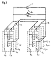
- FIG. 3 shows a section from a third exemplary embodiment of the quartz oscillator according to the invention.
- the elements with the same reference numerals as in Fig. 2 correspond to the same elements.
- the control signal source, operating voltage source, and test signal source and the corresponding supply lines are not shown. They are implemented in the same way as in FIG. 2.
- Fig. 3 several basic cells Z 1 , Z 2 ... Z i are combined into a group in which a resistor R 1 is connected behind the common output of the inverter stages of the group of basic cells.
- the basic cells Z j ... Z j + n form a second group of basic cells, behind the output of which a resistor R j is connected.
- the complexity and area of the IC are reduced, since a common resistor R 1 , R j is used for a certain number of basic cells.
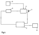
- the quartz oscillator according to the invention is operated in a control loop.
- the quartz crystal 1 is located outside the IC, all other elements are integrated on the IC.
- the output signal of the oscillator circuit 2 is fed to a comparison device 7 for frequency comparison with a reference signal from a reference frequency source 8.
- the output signal of the comparison device 7 is dependent on the difference between the frequencies of the output signal of the oscillator circuit and the reference frequency source 8.
- a digital signal is generated in the control signal source and is supplied to the oscillator circuit 2. This signal determines which of the capacitances C 1i , C 2i are switched on or off. As a result, the frequency of the oscillator circuit 2 is changed accordingly.
Landscapes
- Oscillators With Electromechanical Resonators (AREA)
Abstract
Description
- Die Erfindung betrifft einen digital einstellbaren Quarzoszillator mit einer monolithisch integrierten Oszillatorschaltung, die eine zu dem Schwingquarz parallel geschaltete Serienschaltung mit einer ersten und einer zweiten Frequenzeinstellkapazität C1, C2, von denen zumindest eine digital schaltbar ist, und eine zu dem Schwingquarz parallelgeschaltete Inverterschaltung mit einem parallelgeschalteten Rückkopplungswiderstand RK und einem hinter den Ausgang der Inverterschaltung geschalteten Widerstand R enthält.
- Ein derartiger Quarzoszillator, der in einer Parallelresonanzschaltung betrieben wird, ist aus "Entwurf von Quarzoszillatoren", Bernd Neubig, UKW-Berichte 19 (1979), Heft 2 und 3 bekannt. Es handelt sich dabei um einen Pierce-Oszillator. Dieser kann dazu verwendet werden, für eine integrierte Schaltung eine stabile Frequenz zur Verfügung zu stellen, die durch die schaltbare Frequenzeinstellkapazität in einem geringen Bereich veränderbar ist. Hierbei wird die hohe Güte des Quarzes, seine geringe Alterung und Temperaturdrift und die hohe Herstellungsgenauigkeit dazu ausgenutzt, stabile Frequenzen zu erzeugen. Über eine Regelschleife (PLL-phase locked loop) kann durch Schalten der Kapazitäten eine Synchronisierung des Quarzoszillators mit einer vorgegebenen Frequenz durchgeführt werden. Der Rückkopplungswiderstand RK ist hochohmig und dient dazu, den Arbeitspunkt der Inverterschaltung einzustellen. Der Widerstand R hinter dem Ausgang der Inverterschaltung wird so dimensioniert, daß er für eine konstante Amplitude des Oszillators sorgt. Er ist von der Transkonduktanz der Inverterschaltung und der Größe der Frequenzeinstellkapazitäten C1, C2 abhängig.
- Nachteilig an dieser Oszillatorschaltung ist, daß Frequenzänderungen nur in geringem Maße möglich sind. Denn mit der Frequenzänderung, d.h. mit der Änderung der Frequenzeinstellkapazitäten C1, C2 ändern sich die Bedingungen für eine stabile Schwingung des Quarzoszillators, insbesondere für stabile Frequenz und stabile Amplitude. Es ändern sich sowohl die Anforderungen an die Transkonduktanz der Inverterschaltung als auch an den hinter ihren Ausgang geschalteten Widerstand R.
- Der Erfindung liegt die Aufgabe zugrunde, eine Oszillatorschaltung zu schaffen, mit der eine Frequenzänderung in einem größeren Bereich möglich ist.
- Diese Aufgabe wird durch einen gattungsgemäßen Quarzoszillator gelöst, bei dem die Inverterschaltung zueinander parallelgeschaltete Inverterstufen, die erste Kapazität zueinander parallel geschaltete Kapazitätsstufen und die zweite Kapazität C1, C2 jeweils zueinander parallelgeschaltete zweite Kapazitätsstufen umfaßt, und Schaltelemente derart vorgesehen sind, daß jeweils eine Inverterstufe und eine erste und eine zweite Kapazitätsstufe mit einem Steuersignal gleichzeitig an- bzw. abschaltbar sind.
- Da bei dem erfindungsgemäßen Oszillator mit dem Hinzunehmen bzw. Wegschalten der Kapazitätsstufen, welche die Frequenzänderung bedingen, gleichzeitig eine Inverterstufe hinzugefügt bzw. weggeschaltet wird, wird mit der Frequenzänderung die Transkonduktanz an die geänderte Frequenz angepaßt. Somit ist eine stabile Schwingung des Quarzoszillators über einen weiteren Frequenzbereich möglich.
- Gemäß einer vorteilhaften Weiterbildung der Erfindung enthält eine Inverterstufe jeweils zwei in Reihe geschalte, jeweils mit einem festen Potential verbundene Verstärkertransistoren von entgegengesetztem Leitfähigkeitstyp, mit denen jeweils ein als Schaltelement wirkender Schalttransistor des gleichen Leitfähigkeitstyps in Reihe geschaltet ist. Die erste Kapazitätsstufe ist jeweils über ein Schaltelement mit den Gate-Elektroden der Verstärkertransistoren verbunden. Die zweite Kapazitätsstufe ist jeweils über ein zweites Schaltelement mit dem Widerstand R verbunden. Der Widerstand R ist dabei abhängig von der Größe der Transkonduktanz der Inverterstufe so gewählt, daß eine konstante Amplitude der Oszillatorschwingung erreicht wird. Die Transkonduktanz der Inverterstufe wird durch die Dimensionierung der Verstärkertransistoren bestimmt. Es ist vorteilhaft, die Verstärkertransistoren und die Schalttransistoren als CMOS-Transistoren auszubilden.
- Gemäß einer vorteilhaften Weiterbildung der Erfindung ist in den Inverterstufen jeweils in Reihe mit dem Verstärkertransistor und dem Schalttransistor eines Leitfähigkeitstyps ein weiterer Testschalttransistor des gleichen Leitfähigkeitstyps geschaltet, und eine Testsignalquelle ist derart angeordnet, daß mit einem von dieser gelieferten Testsignal die Schalttransistoren in den leitenden oder nichtleitenden Zustand schaltbar sind, und gleichzeitig der Rückkopplungswiderstand RK über Testschältmittel zu- oder abschaltbar ist. Hierdurch wird erreicht, daß der Quarzoszillator mit dem Testsignal wahlweise in einen Normalzustand, in dem der Quarzoszillator schwingt, und in einen Testzustand geschaltet werden kann. Für den Normalzustand werden die Testchalttransistoren von dem Testsignal in den leitenden Zustand geschaltet, und der Rückkopplungswiderstand wird hinzugeschaltet, so daß der Quarzoszillator auf seiner Resonanzfrequenz schwingt. Für den Testzustand werden die Schalttransistoren mit dem Testsignal in den nichtleitenden Zustand geschaltet, und der Rückkopplungswiderstand wird abgeschaltet. Hierdurch wird die jeweilige Inverterstufe stromlos, und die Rückkopplung wird unterbrochen. In diesem Zustand können die Kapazitäten der verschiedenen Inverterstufen über die dazugehörigen Schaltelemente eingeschaltet werden. In dem Testzustand ist es möglich, die Leckströme der Kapazitäten der Inverterstufen zu messen. Dies ist nur im Testzustand möglich, da die Kapazitäten im Normalzustand jeweils über den Widerstand R an den Ausgang der Kaskodenstufen der jeweiligen Inverterstufe angeschlossen sind. Zudem erfolgt diese Verbindung über den Rückkopplungszweig mit dem Kopplungswiderstand RK, so daß der Strom in der gesamten Oszillatorschaltung fließen würde. Dadurch, daß getestet werden kann, ob die Kondensatoren Leckströme aufweisen oder nicht, wird es möglich, in dem Testzustand festzustellen, ob der Quarzoszillator den von Anwender und Hersteller vorgegebenen Anforderungen genügt. Für viele Anwendungen ist eine Leckstromfreiheit auf Dauer erforderlich. Somit können aufgrund der Untersuchungen im Testzustand die den Anforderungen genügenden bzw. nicht genügenden Oszillatorschaltungen bestimmt und aussortiert werden. Die Leckströme können insbesondere durch schlechte Oxideigenschaften des Oxids zwischen den Kondensatorplatten zustande kommen. Die Leckstromfreiheit kann bei einer bestimmten Spannung und bei einer bestimmten Temperatur überprüft werden, woraus auf eine Leckstromfreiheit für eine lange Zeit unter Normalbedingungen geschlossen werden kann.
- Günstigerweise kann der Rückkopplungswiderstand RK komplementäre, als Testschaltmittel wirkende Transistoren umfassen, deren Gate-Elektroden mit der Testsignalquelle verbunden sind. Dadurch ist der Rückkopplungswiderstand durch Schalten der Transistoren mit dem von der Testsignalquelle gelieferten Testsignal einfach an- und abschaltbar.
- Ferner ist es vorteilhaft, wenn die Testschalttransistoren jeweils zwischen den Verstärkertransistor und den Schalttransistor geschaltet sind. Dann bilden die Schalttransistoren am Ausgang der jeweiligen Inverterstufe in ihrem ausgeschalteten Zustand einen hochohmigen Widerstand, so daß die Gatekapazität der Testschalttransistoren nicht in die parallelgeschaltete Frequenzeinstellkapazität C1, C2 eingeht. Die Gatekapazität wird im leitenden Zustand durch die Kapazität zwischen der Gate-Elektrode und dem vorhandenen Kanal zwischen Drain- und Source-Zone gebildet. Da die Testschalttransistoren im Normalzutsand des Quarzoszillators immer leitend sind, weisen sie im Normalzustand auch immer eine Gatekapazität auf.
- Auch ist es günstig, wenn der Widerstand R Teilwiderstände umfaßt, von denen jeweils einer hinter den Ausgang einer oder mehrerer Inverterstufen geschaltet ist. Da der Widerstand R für eine konstante Amplitude der Schwingung sorgt, muß dieser bei einer starken Frequenzänderung, welche durch Hinzuschalten verschiedener Kapazitäten entsteht, entsprechend angepaßt werden. Abhängig davon, wie stark die Kapazität durch Hinzuschalten von einzelnen Stufen geändert wird, kann hinter dem Ausgang einer jeden Inverterstufe oder hinter dem Ausgang einer Gruppe von Inverterstufen ein Teilwiderstand Ri geschaltet werden.
- Gemäß einem weiteren Ausführungsbeispiel der Erfindung ist die Anzahl der ersten und die Anzahl der zweiten Kapazitätsstufen jeweils größer, als die Anzahl der Inverterstufen, und es sind Schaltelemente derart vorgesehen, daß eine erste und eine zweite Kapazitätsstufe mit einem Steuersignal an- bzw. abschaltbar sind. Somit kann eine geeignete Anzahl von Kapazitätsstufen auch ohne Inverterstufen an- bzw. abgeschaltet werden. Dies ist für die Frequenzbereiche sinnvoll, in denen die Stabilität der Oszillatorschwingung durch eine Kapazitätsänderung nicht ungewünscht beeinträchtigt wird. Es können abwechselnd Kapazitätsstufen mit und ohne Inverterstufe an- bzw. abgeschaltet werden.
- Im folgenden wird die Erfindung anhand der Zeichnung näher erläutert.
- Es zeigen:
- Fig. 1 ein erstes Ausführungsbeispiel des erfindungsgemäßen Quarzoszillators,
- Fig. 2 ein zweites Ausführungsbeispiel des erfindungsgemäßen Quarzoszillators,
- Fig. 3 ein drittes Ausführungsbeispiel des erfindungsgemäßen Quarzoszillators und
- Fig. 4 ein Blockschaltbild, das eine den erfindungsgemäßen Quarzoszillator enthaltende Regelschleife darstellt.
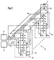
- Die Fig. 1 zeigt einen Quarzoszillator mit einem Schwingquarz 1 und einer Oszillatorschaltung 2. Die Oszillatorschaltung 2 ist auf einem Halbleiterchip in CMOS-Technologie integriert. Der Schwingquarz 1 befindet sich außerhalb des Halbleiterchips. Parallelgeschaltet zu dem Schwingquarz 1 sind n Grundzellen Z1 ... Zn, zu denen wiederum ein Rückkopplungswiderstand RK parallelgeschaltet ist.
- Jede der Grundzellen Zi umfaßt zwei Kapazitäten C1i, C2i, welche zu dem Quarz 1 parallelgeschaltet sind, wobei jeweils ein Anschluß an das Massepotential angeschlossen ist. Zudem enthält jede Grundzelle Zi eine zu dem Quarz 1 parallelgeschaltete Inverterstufe, zwei in Reihe geschaltete, mit einem festen Potential, der Betriebsspannung VDD bzw. Masse, verbundene Verstärkertransistoren p1i, n1i. Mit diesen ist jeweils ein Schalttransistor p2i, n2i des gleichen Leitfähigkeitstyps in Reihe geschaltet. Am Ausgang der Inverterstufe ist ein Widerstand Ri angeschlossen. Die erste Kapazität C1i ist über einen Schalter S1i an die miteinander verbundenen Gate-Elektroden der Verstärkertransistoren p1i und n1i angeschlossen. Die zweite Kapazität C2i ist über einen zweiten Schalter S2i mit dem Widerstand Ri verbunden. Eine Steuersignalquelle 3 liefert Steuersignale I1 ... In. Mit dem Steuersignal Ii werden jeweils die Schalter S1i, S2i der jeweiligen Grundzelle Zi eingeschaltet. Gleichzeitig wird mit dem Steuersignal Ii der Transistor n2i und mit dem dazu inversen Signal IQi der Transistor p2i eingeschaltet. Dabei wird das Steuersignal Ii durch einen Inverter 5 zu dem Signal IQi invertiert.
- Durch die Anzahl der geschlossenen Schalter S1i, S2i in den Grundzellen Zi wird die wirksame Lastkapazität des Schwingquarzes 1 und damit die Resonanzfrequenz des Quarzoszillators bestimmt. Damit ein stabiles Schwingen bei einer bestimmten Resonanzfrequenz erreicht wird, muß die Transkonduktanz an die jeweilige Resonanzfrequenz angepaßt werden. Dies erfolgt dadurch, daß mit Hinzuschalten der Kapazitäten C1i, C2i gleichzeitig die Schalttransistoren p2i, n2i mit dem gemeinsamen Steuersignal Ii bzw. IQi eingeschaltet werden. Somit wird die jeweilige Inverterstufe und der dieser nachgeschaltete Widerstand Ri gleichzeitig mit den Kapazitäten hinzugeschaltet. Die Inverterstufe sorgt für eine geeignete Verstärkung bei der geänderten Resonanzfrequenz, der Widerstand Ri sorgt für eine konstante Amplitude der Schwingung. Die Größe des Widerstandes Ri wird abhängig von der Größe der Verstärkung der Inverterstufe und somit abhängig von den Kapazitätsstufen und der Dimensionierung der Verstärkertransistoren n1i, p1i gewählt.
- Der Rückkopplungswiderstand RK enthält zwei komplementäre Rückkopplungstransistoren prK und nrK. Der Rückkopplungswiderstand RK stellt den Arbeitspunkt der Grundzellen Vi ein. Die Schalter S1i, S2i können aus komplementären Transistoren bestehen, denen das Steuersignal Ii und das inverse Steuersignal IQi zugeführt wird.
- Fig. 2 zeigt ein zweites Ausführungsbeispiel des erfindungsgemäßen Quarzoszillators. Gleiche Bezugszeichen, wie die in Fig. 1 verwendeten, beziehen sich auf die gleichen Teile des Quarzoszillators. Es werden daher im folgenden nur die Änderungen beschrieben. Die Inverterstufen der Grundzellen Zi enthalten zwei weitere Testtransistoren von entgegengesetztem Leitungstyp pti, nti. Diese sind jeweils zwischen den Verstärkertransistor p1i , n1i und den Schalttransistor p2i , n2i vom gleichen Leitfähigkeitstyp in Reihe geschaltet. Die Gate-Elektroden der Testtransistoren pti, nti werden mit einem Signal T bzw. TQ, das von einer Testsignalquelle 6 geliefert wird, angesteuert. Die Testsignalquelle 6 ist ebenfalls mit dem Rückkopplungswiderstand RK verbunden. Die Testsignale T, TQ steuern die Gate-Elektroden der Rückkopplungstransistoren prk und nrk des Rückkopplungswiderstands RK. Im Normalzustand liefert die Testsignalquelle 6 die Testsignale T und TQ so, daß die Testtransistoren pti, nti und die Rückkopplungstransistoren prk , nrk leitend sind. Die Funktion des Oszillators in dem Normalzustand entspricht der Funktion des Oszillators aus Fig. 1. Im Testzustand liefert die Testsignalquelle 6 die Testsignale T und TQ so, daß die Testtransistoren pti, nni und die Rückkopplungstransistoren prk, nrk nicht leitend sind. In diesem Fall sind die jeweiligen Inverterstufen stromlos und die Rückkopplung ist unterbrochen. Wenn die Kapazitäten C1i und C2i über die Schalter S1i, S2i eingeschaltet werden, können die Leckströme der Kapazitäten C1i, C2i ohne Einfluß der übrigen Schaltungselemente gemessen werden. Alternativ kann dieser Testzustand auch dadurch realisiert werden, daß die Leitungen mit dem Steuersignal Ii über eine Logikschaltung, z. B. einer OR-Schaltung, mit dem Testsignal T verbunden werden.
- Die Widerstände Ri dieses Ausführungsbeispiels sind so dimensioniert, daß die Widerstände der Testtransistoren nti, pti in ihrem An-Zustand mitberücksichtigt sind. Die Widerstände Ri sind in Fig. 2 daher niederohmiger als in der Figur 1.
- Fig. 3 zeigt einen Ausschnitt aus einem dritten Ausführungsbeispiel des erfindungsgemäßen Quarzoszillators. Die Elemente mit dem gleichen Bezugszeichen wie in Fig. 2 entsprechen den gleichen Elementen. Zur Vereinfachung und Übersichtlichkeit sind Steuersignalquelle, Betriebsspannungsquelle, Testsignalquelle und die entsprechenden Zuleitungen nicht dargestellt. Sie werden analog wie in Fig. 2 realisiert. In Fig. 3 sind mehrere Grundzellen Z1, Z2 ... Zi zu einer Gruppe zusammengefaßt, bei denen ein Widerstand R1 hinter den gemeinsamen Ausgang der Inverterstufen der Gruppe der Grundzellen geschaltet ist. Die Grundzellen Zj ... Zj + n bilden eine zweite Gruppe von Grundzellen, hinter deren Ausgang ein Widerstand Rj geschaltet ist. Bei diesem Ausführungsbeispiel werden Aufwand und Fläche des IC's reduziert, da für eine bestimmte Anzahl von Grundzellen ein gemeinsamer Widerstand R1, Rj verwendet wird.
- Fig. 4 zeigt ein Blockschaltbild in dem der erfindungsgemäße Quarzoszillator in einer Regelschleife betrieben wird. Der Schwingquarz 1 befindet sich außerhalb des IC's, alle anderen Elemente sind auf dem IC integriert. Das Ausgangssignal der Oszillatorschaltung 2 wird einer Vergleichseinrichtung 7 zum Frequenzvergleich mit einem Referenzsignal aus einer Referenzfrequenzquelle 8 zugeführt. Das Ausgangssignal der Vergleichseinrichtung 7 ist abhängig von dem Unterschied der Frequenzen des Ausgangssignals der Oszillatorschaltung und der Referenzfrequenzquelle 8. Abhängig von dem Ausgangssignal der Vergleichseinrichtung 7 wird in der Steuersignalquelle ein digitales Signal erzeugt, das der Oszillatorschaltung 2 zugeführt wird. Dieses Signal bestimmt, welche der Kapazitäten C1i, C2i zu- oder abgeschaltet werden. Dadurch wird entsprechend die Frequenz der Oszillatorschaltung 2 geändert. Diese Regelung erfolgt so lange, bis die Vergleichseinrichtung 7 Frequenzübereinstimmung von dem Ausgangssignal der Oszillatorschaltung 2 und dem Ausgangssignal der Referenzfrequenzquelle 8 mißt. Ist dieser Wert erreicht, wird die Frequenz der Oszillatorschaltung festgehalten. Die Testsignalquelle 6 ist in diesem Fall in den Normalzustand geschaltet. Sie wird lediglich zum Testen der Leckstromfreiheit der Kapazitäten in den Testzustand umgeschaltet.
Claims (7)
- Digital einstellbarer Quarzoszillator mit einer monolithisch integrierten Oszillatorschaltung (2),die eine zu dem Schwingquarz parallel geschaltete Serienschaltung mit einer ersten und einer zweiten Frequenzeinstellkapazität C1, C2, von denen zumindest eine digital schaltbar ist, undeine zu dem Schwingquarz (1) parallel geschaltete Inverterschaltung mit einem parallel geschalteten Rückkopplungswiderstand RK und einem hinter den Ausgang der Inverterschaltung geschalteten Widerstand R enthält,
dadurch gekennzeichnet,daß die Inverterschaltung zueinander parallel geschaltete Inverterstufen, die erste Kapazität zueinander parallel geschaltete Kapazitätsstufen (C1i) und die zweite Kapazität C2 zueinander parallel geschaltete zweite Kapazitätsstufen C2i umfaßt, und Schaltelemente (S1i, S2i, p2i, n2i) derart vorgesehen sind, daß jeweils eine Inverterstufe und eine erste und zweite Kapazitätsstufe (C1i, C2i) mit einem Steuersignal (Ii) gleichzeitig an- bzw. abschaltbar sind. - Quarzoszillator nach Anspruch 1, dadurch gekennzeichnet, daß eine Inverterstufe jeweils zwei in Reihe geschaltete, jeweils mit einem festen Potential verbundene Verstärkertransistoren (p1i, n1i) von entgegengesetztem Leitfähigkeitstyp enthält, mit denen jeweils ein als Schaltelement wirkender Schalttransistor (p2i, n2i) des gleichen Leitfähigkeitstyps in Reihe geschaltet ist.
- Quarzoszillator nach Anspruch 2, dadurch gekennzeichnet, daß in den Inverterstufen jeweils in Reihe mit dem Verstärkertransistor (p1i, n1i) und dem Schalttransistor (p2i, n2i) eines Leitfähigkeitstyps ein weiterer Testschalttransistor (pti, nti) des gleichen Leitfähigkeitstyps geschaltet ist, und eine Testsignalquelle derart angeordnet ist, daß mit einem von dieser gelieferten Testsignal die Schalttransistoren (p2i, n2i) in den leitenden oder nichtleitenden Zustand schaltbar sind, und gleichzeitig der Rückkopplungswiderstand RK über Testschaltmittel zu- oder abschaltbar ist.
- Quarzoszillator nach Anspruch 3, dadurch gekennzeichnet, daß der Rückkopplungswiderstand RK ein Paar komplementärer, als Testschaltmittel wirkender Transistoren (prK, nrK) umfaßt, deren Gateelektroden mit der Testsignalquelle (6) verbunden sind.
- Quarzoszillator nach Anspruch 3 oder 4, dadurch gekennzeichnet, daß die Testschalttransistoren (pti, nti) jeweils zwischen Verstärkertransistor (p1i, n1i) und den Schalttransistor (p2i, n2i) geschaltet sind.
- Quarzoszillator nach einem der vorangehenden Ansprüche, dadurch gekennzeichnet, daß der Widerstand R Teilwiderstände (Ri) umfaßt, von denen jeweils einer hinter den Ausgang einer oder mehrerer Inverterstufen geschaltet ist.
- Quarzoszillator nach einem der vorangehenden Ansprüche, dadurch gekennzeichnet, daß die Anzahl der ersten und die Anzahl der zweiten Kapazitätsstufen (C1i, C2i) jeweils größer ist als die Anzahl der Inverterstufen, und daß Schaltelemente (S1K, S2K) derart vorgesehen sind, daß eine erste und eine zweite Kapazitätsstufe (C1K, C2K) mit einem Steuersignal (IK) an- bzw. abschaltbar sind.
Applications Claiming Priority (2)
| Application Number | Priority Date | Filing Date | Title |
|---|---|---|---|
| DE19621228 | 1996-05-25 | ||
| DE19621228A DE19621228A1 (de) | 1996-05-25 | 1996-05-25 | Digital einstellbarer Quarzoszillator mit monolithisch integrierter Oszillatorschaltung |
Publications (2)
| Publication Number | Publication Date |
|---|---|
| EP0809350A1 true EP0809350A1 (de) | 1997-11-26 |
| EP0809350B1 EP0809350B1 (de) | 2002-03-20 |
Family
ID=7795392
Family Applications (1)
| Application Number | Title | Priority Date | Filing Date |
|---|---|---|---|
| EP97107250A Expired - Lifetime EP0809350B1 (de) | 1996-05-25 | 1997-05-02 | Digital einstellbarer Quarzoszillator mit monolithisch integrierter Oszillatorschaltung |
Country Status (4)
| Country | Link |
|---|---|
| US (1) | US5805029A (de) |
| EP (1) | EP0809350B1 (de) |
| KR (1) | KR100441470B1 (de) |
| DE (2) | DE19621228A1 (de) |
Families Citing this family (15)
| Publication number | Priority date | Publication date | Assignee | Title |
|---|---|---|---|---|
| DE19812391B4 (de) * | 1998-03-20 | 2006-02-02 | Infineon Technologies Ag | Oszillatorschaltung |
| GB2349995A (en) | 1999-05-14 | 2000-11-15 | Ericsson Telefon Ab L M | An oscillator in which when the frequency is adjusted the level is also adjusted |
| KR100407193B1 (ko) * | 1999-05-14 | 2003-11-28 | 신성전자공업 주식회사 | 온도 적응형 커패시터 블록 및 이를 이용한 온도 보상 수정발진기 |
| US8363757B1 (en) | 1999-10-12 | 2013-01-29 | Qualcomm Incorporated | Method and apparatus for eliminating the effects of frequency offsets in a digital communication system |
| JP3593963B2 (ja) | 2000-08-29 | 2004-11-24 | セイコーエプソン株式会社 | 電圧制御発振器、電圧制御発振器用icチップ、抵抗調整装置及び抵抗調整方法 |
| US20030132809A1 (en) * | 2002-01-17 | 2003-07-17 | Chinnugounder Senthilkumar | Oscillator with tunable capacitor |
| GB2384927A (en) * | 2002-02-05 | 2003-08-06 | Zarlink Semiconductor Ltd | Voltage controlled oscillators |
| US6628175B1 (en) | 2002-03-27 | 2003-09-30 | Pericom Semiconductor Corp. | Voltage-controlled crystal oscillator (VCXO) using MOS varactors coupled to an adjustable frequency-tuning voltage |
| KR100760196B1 (ko) * | 2005-12-08 | 2007-09-20 | 한국전자통신연구원 | 적응성 부성 저항셀을 장착한 멀티밴드용 lc 공조전압제어발진기 |
| US7961060B1 (en) * | 2007-06-19 | 2011-06-14 | Cypress Semiconductor Corporation | Amplitude regulated resonant oscillator with sampled feedback |
| US20110096864A1 (en) * | 2009-10-28 | 2011-04-28 | Maxlinear, Inc. | Programmable digital clock control scheme to minimize spur effect on a receiver |
| CN102118131B (zh) * | 2009-12-31 | 2016-06-15 | 意法-爱立信公司 | 缩短晶体振荡器的启动时间的方法 |
| US8686798B2 (en) * | 2011-05-19 | 2014-04-01 | Freescale Semiconductor, Inc. | Method and system for testing oscillator circuit |
| TWI566517B (zh) * | 2015-06-16 | 2017-01-11 | 智原科技股份有限公司 | 晶體振盪電路、此晶體振盪電路的增益級及其設計方法 |
| US12531513B2 (en) * | 2024-04-15 | 2026-01-20 | Nxp B.V. | Crystal oscillator with on-chip negative resistance margin measurement circuit |
Citations (5)
| Publication number | Priority date | Publication date | Assignee | Title |
|---|---|---|---|---|
| JPS5528632A (en) * | 1978-08-22 | 1980-02-29 | Seiko Instr & Electronics Ltd | Crystal oscillator circuit unit |
| US4814640A (en) * | 1986-02-27 | 1989-03-21 | Ricoh Company, Ltd. | Electrically trimmable semiconductor device |
| EP0398331A2 (de) * | 1989-05-17 | 1990-11-22 | Kabushiki Kaisha Toshiba | Oszillatorschaltkreis innerhalb eines Halbleiterschaltkreises |
| JPH05136707A (ja) * | 1991-11-12 | 1993-06-01 | Kokusai Electric Co Ltd | クロツク発振回路 |
| EP0641080A2 (de) * | 1993-08-25 | 1995-03-01 | Motorola, Inc. | Verfahren und Vorrichtung zur Verringerung des Jitters und Verbesserung der Testbarkeit eines Oszillators |
Family Cites Families (3)
| Publication number | Priority date | Publication date | Assignee | Title |
|---|---|---|---|---|
| US5077529A (en) * | 1989-07-19 | 1991-12-31 | Level One Communications, Inc. | Wide bandwidth digital phase locked loop with reduced low frequency intrinsic jitter |
| JP3019340B2 (ja) * | 1989-12-05 | 2000-03-13 | セイコーエプソン株式会社 | 可変容量装置 |
| US5142251A (en) * | 1991-10-03 | 1992-08-25 | National Semiconductor Corporation | Wide band selectable gain and operating frequency CMOS oscillator circuit |
-
1996
- 1996-05-25 DE DE19621228A patent/DE19621228A1/de not_active Withdrawn
-
1997
- 1997-05-02 DE DE59706648T patent/DE59706648D1/de not_active Expired - Lifetime
- 1997-05-02 EP EP97107250A patent/EP0809350B1/de not_active Expired - Lifetime
- 1997-05-22 US US08/861,605 patent/US5805029A/en not_active Expired - Lifetime
- 1997-05-23 KR KR1019970020181A patent/KR100441470B1/ko not_active Expired - Fee Related
Patent Citations (5)
| Publication number | Priority date | Publication date | Assignee | Title |
|---|---|---|---|---|
| JPS5528632A (en) * | 1978-08-22 | 1980-02-29 | Seiko Instr & Electronics Ltd | Crystal oscillator circuit unit |
| US4814640A (en) * | 1986-02-27 | 1989-03-21 | Ricoh Company, Ltd. | Electrically trimmable semiconductor device |
| EP0398331A2 (de) * | 1989-05-17 | 1990-11-22 | Kabushiki Kaisha Toshiba | Oszillatorschaltkreis innerhalb eines Halbleiterschaltkreises |
| JPH05136707A (ja) * | 1991-11-12 | 1993-06-01 | Kokusai Electric Co Ltd | クロツク発振回路 |
| EP0641080A2 (de) * | 1993-08-25 | 1995-03-01 | Motorola, Inc. | Verfahren und Vorrichtung zur Verringerung des Jitters und Verbesserung der Testbarkeit eines Oszillators |
Non-Patent Citations (3)
| Title |
|---|
| PATENT ABSTRACTS OF JAPAN vol. 004, no. 059 (E - 009) 2 May 1980 (1980-05-02) * |
| PATENT ABSTRACTS OF JAPAN vol. 017, no. 518 (E - 1434) 17 September 1993 (1993-09-17) * |
| SHIGEO KUBOKI ET AL: "DESIGN CONSIDERATIONS FOR LOW-VOLTAGE CRYSTAL OSCIL-LATOR CIRCUIT IN A 1.8-V SINGLE CHIP MICROPROCESSOR", IEICE TRANSACTIONS ON ELECTRONICS, vol. E76-C, no. 5, 1 May 1993 (1993-05-01), pages 701 - 707, XP000381111 * |
Also Published As
| Publication number | Publication date |
|---|---|
| EP0809350B1 (de) | 2002-03-20 |
| KR970077955A (ko) | 1997-12-12 |
| DE19621228A1 (de) | 1997-11-27 |
| US5805029A (en) | 1998-09-08 |
| DE59706648D1 (de) | 2002-04-25 |
| KR100441470B1 (ko) | 2004-11-03 |
Similar Documents
| Publication | Publication Date | Title |
|---|---|---|
| DE68921532T2 (de) | Transresistanzvorrichtung mit Drain-Vorspannung. | |
| EP0809350B1 (de) | Digital einstellbarer Quarzoszillator mit monolithisch integrierter Oszillatorschaltung | |
| EP0236525B1 (de) | Integrierte Isolierschicht-Feldeffekttransistor-Verzögerungsleitung für Digitalsignale | |
| DE102015105113A1 (de) | System und Verfahren zum Ansteuern eines Hochfrequenzschalters | |
| DE1812292C3 (de) | Schaltungsanordnung zur Verstärkungsregelung | |
| CH690950A5 (de) | Temperaturstabilisierter Oszillator und Verwendung desselben in einem Näherungsschalter. | |
| DE2427835A1 (de) | Frequenzumsetzer | |
| DE3327488C2 (de) | Zweirichtungs-Verstärker für bidirektionale Datenleitungen | |
| WO2002015394A1 (de) | Differentieller, komplementärer verstärker | |
| EP1553701A1 (de) | Schaltungsanordnung zur Erzeugung eines digitalen Clocksignals | |
| WO2001067594A1 (de) | Schaltungsanordnung zur arbeitspunkteinstellung eines hochfrequenztransistors und verstärkerschaltung | |
| DE4306511C2 (de) | Filterschaltung mit einem in Serienresonanz betriebenen Resonator | |
| DE3436302A1 (de) | Rauschfreie, die bauelementflaeche beeinflussende kaskodenschaltung | |
| DE102004022991B3 (de) | Abtast-Differenzverstärker und Abtast-Verstärker | |
| EP0078084A2 (de) | Schaltungsanordnung mit einem umschaltbaren Glättungsglied | |
| EP1146640A1 (de) | Integrierter Hochfrequenzschwingkreis mit Abgleichkondensatoren | |
| EP1742350A2 (de) | Integrierte Quarzoszillatorschaltung | |
| DE102007063042A1 (de) | Oszillator mit Darlington-Knoten | |
| DE1290193B (de) | Gegengekoppelter Verstaerker mit Stabilisierung | |
| DE3813532A1 (de) | Umschaltbarer differenzverstaerker | |
| EP1293785B1 (de) | Spannungskomparator | |
| DE3327107A1 (de) | Hochfrequenzverstaerkerschaltung | |
| DE2903659A1 (de) | Monolithisch integrierbare logikschaltung | |
| DE3737862C2 (de) | ||
| DE1537606C (de) | Gleichstromverstärker mit Schaltung zur Driftkompensation |
Legal Events
| Date | Code | Title | Description |
|---|---|---|---|
| PUAI | Public reference made under article 153(3) epc to a published international application that has entered the european phase |
Free format text: ORIGINAL CODE: 0009012 |
|
| AK | Designated contracting states |
Kind code of ref document: A1 Designated state(s): DE FR GB IT NL |
|
| RAP1 | Party data changed (applicant data changed or rights of an application transferred) |
Owner name: MICRONAS SEMICONDUCTOR HOLDING AG |
|
| 17P | Request for examination filed |
Effective date: 19980526 |
|
| 17Q | First examination report despatched |
Effective date: 20000510 |
|
| GRAG | Despatch of communication of intention to grant |
Free format text: ORIGINAL CODE: EPIDOS AGRA |
|
| GRAG | Despatch of communication of intention to grant |
Free format text: ORIGINAL CODE: EPIDOS AGRA |
|
| GRAH | Despatch of communication of intention to grant a patent |
Free format text: ORIGINAL CODE: EPIDOS IGRA |
|
| REG | Reference to a national code |
Ref country code: GB Ref legal event code: IF02 |
|
| GRAH | Despatch of communication of intention to grant a patent |
Free format text: ORIGINAL CODE: EPIDOS IGRA |
|
| GRAA | (expected) grant |
Free format text: ORIGINAL CODE: 0009210 |
|
| AK | Designated contracting states |
Kind code of ref document: B1 Designated state(s): DE FR GB IT NL |
|
| REF | Corresponds to: |
Ref document number: 59706648 Country of ref document: DE Date of ref document: 20020425 |
|
| ET | Fr: translation filed | ||
| GBT | Gb: translation of ep patent filed (gb section 77(6)(a)/1977) |
Effective date: 20020625 |
|
| RAP2 | Party data changed (patent owner data changed or rights of a patent transferred) |
Owner name: MICRONAS SEMICONDUCTOR HOLDING AG |
|
| PLBE | No opposition filed within time limit |
Free format text: ORIGINAL CODE: 0009261 |
|
| STAA | Information on the status of an ep patent application or granted ep patent |
Free format text: STATUS: NO OPPOSITION FILED WITHIN TIME LIMIT |
|
| NLT2 | Nl: modifications (of names), taken from the european patent patent bulletin |
Owner name: MICRONAS SEMICONDUCTOR HOLDING AG |
|
| 26N | No opposition filed |
Effective date: 20021223 |
|
| REG | Reference to a national code |
Ref country code: FR Ref legal event code: TP |
|
| PGFP | Annual fee paid to national office [announced via postgrant information from national office to epo] |
Ref country code: FR Payment date: 20100601 Year of fee payment: 14 |
|
| PGFP | Annual fee paid to national office [announced via postgrant information from national office to epo] |
Ref country code: NL Payment date: 20100524 Year of fee payment: 14 Ref country code: IT Payment date: 20100526 Year of fee payment: 14 |
|
| REG | Reference to a national code |
Ref country code: GB Ref legal event code: 732E Free format text: REGISTERED BETWEEN 20101014 AND 20101020 |
|
| REG | Reference to a national code |
Ref country code: NL Ref legal event code: SD Effective date: 20101028 |
|
| PGFP | Annual fee paid to national office [announced via postgrant information from national office to epo] |
Ref country code: GB Payment date: 20100525 Year of fee payment: 14 |
|
| REG | Reference to a national code |
Ref country code: NL Ref legal event code: V1 Effective date: 20111201 |
|
| GBPC | Gb: european patent ceased through non-payment of renewal fee |
Effective date: 20110502 |
|
| PG25 | Lapsed in a contracting state [announced via postgrant information from national office to epo] |
Ref country code: NL Free format text: LAPSE BECAUSE OF NON-PAYMENT OF DUE FEES Effective date: 20111201 |
|
| REG | Reference to a national code |
Ref country code: FR Ref legal event code: ST Effective date: 20120131 |
|
| PG25 | Lapsed in a contracting state [announced via postgrant information from national office to epo] |
Ref country code: IT Free format text: LAPSE BECAUSE OF NON-PAYMENT OF DUE FEES Effective date: 20110502 |
|
| REG | Reference to a national code |
Ref country code: DE Ref legal event code: R084 Ref document number: 59706648 Country of ref document: DE Effective date: 20110426 |
|
| PG25 | Lapsed in a contracting state [announced via postgrant information from national office to epo] |
Ref country code: FR Free format text: LAPSE BECAUSE OF NON-PAYMENT OF DUE FEES Effective date: 20110531 |
|
| PG25 | Lapsed in a contracting state [announced via postgrant information from national office to epo] |
Ref country code: GB Free format text: LAPSE BECAUSE OF NON-PAYMENT OF DUE FEES Effective date: 20110502 |
|
| PGFP | Annual fee paid to national office [announced via postgrant information from national office to epo] |
Ref country code: DE Payment date: 20120529 Year of fee payment: 16 |
|
| REG | Reference to a national code |
Ref country code: DE Ref legal event code: R082 Ref document number: 59706648 Country of ref document: DE Representative=s name: EPPING HERMANN FISCHER, PATENTANWALTSGESELLSCH, DE |
|
| REG | Reference to a national code |
Ref country code: DE Ref legal event code: R082 Ref document number: 59706648 Country of ref document: DE Representative=s name: EPPING HERMANN FISCHER, PATENTANWALTSGESELLSCH, DE Effective date: 20121023 Ref country code: DE Ref legal event code: R081 Ref document number: 59706648 Country of ref document: DE Owner name: ENTROPIC COMMUNICATIONS, INC., US Free format text: FORMER OWNER: TRIDENT MICROSYSTEMS (FAR EAST) LTD., GRAND CAYMAN, KY Effective date: 20121023 |
|
| PG25 | Lapsed in a contracting state [announced via postgrant information from national office to epo] |
Ref country code: DE Free format text: LAPSE BECAUSE OF NON-PAYMENT OF DUE FEES Effective date: 20131203 |
|
| REG | Reference to a national code |
Ref country code: DE Ref legal event code: R119 Ref document number: 59706648 Country of ref document: DE Effective date: 20131203 |