EP0808988B1 - Piston creux avec un fond soudé radialement - Google Patents
Piston creux avec un fond soudé radialement Download PDFInfo
- Publication number
- EP0808988B1 EP0808988B1 EP97106176A EP97106176A EP0808988B1 EP 0808988 B1 EP0808988 B1 EP 0808988B1 EP 97106176 A EP97106176 A EP 97106176A EP 97106176 A EP97106176 A EP 97106176A EP 0808988 B1 EP0808988 B1 EP 0808988B1
- Authority
- EP
- European Patent Office
- Prior art keywords
- main body
- cover
- mandrel
- hollow piston
- jacket
- Prior art date
- Legal status (The legal status is an assumption and is not a legal conclusion. Google has not performed a legal analysis and makes no representation as to the accuracy of the status listed.)
- Expired - Lifetime
Links
- 238000003466 welding Methods 0.000 claims description 48
- 238000000034 method Methods 0.000 claims description 25
- 238000010894 electron beam technology Methods 0.000 claims description 13
- 238000004519 manufacturing process Methods 0.000 claims description 8
- 230000002093 peripheral effect Effects 0.000 claims description 3
- 238000010438 heat treatment Methods 0.000 claims description 2
- 230000001105 regulatory effect Effects 0.000 claims description 2
- 238000001746 injection moulding Methods 0.000 claims 2
- 238000005304 joining Methods 0.000 claims 1
- 230000001360 synchronised effect Effects 0.000 claims 1
- 238000000137 annealing Methods 0.000 description 7
- 238000013461 design Methods 0.000 description 6
- 239000000463 material Substances 0.000 description 6
- 239000011324 bead Substances 0.000 description 4
- 238000011161 development Methods 0.000 description 2
- 230000018109 developmental process Effects 0.000 description 2
- 239000007787 solid Substances 0.000 description 2
- 238000012549 training Methods 0.000 description 2
- 208000008454 Hyperhidrosis Diseases 0.000 description 1
- 238000010276 construction Methods 0.000 description 1
- 230000006866 deterioration Effects 0.000 description 1
- 238000006073 displacement reaction Methods 0.000 description 1
- 238000005553 drilling Methods 0.000 description 1
- 239000012530 fluid Substances 0.000 description 1
- 238000003780 insertion Methods 0.000 description 1
- 230000037431 insertion Effects 0.000 description 1
- 238000003754 machining Methods 0.000 description 1
- 230000000149 penetrating effect Effects 0.000 description 1
- 238000003825 pressing Methods 0.000 description 1
- 238000011112 process operation Methods 0.000 description 1
- 238000012545 processing Methods 0.000 description 1
- 230000005855 radiation Effects 0.000 description 1
- 210000004243 sweat Anatomy 0.000 description 1
- 208000013460 sweaty Diseases 0.000 description 1
Images


Classifications
-
- B—PERFORMING OPERATIONS; TRANSPORTING
- B23—MACHINE TOOLS; METAL-WORKING NOT OTHERWISE PROVIDED FOR
- B23P—METAL-WORKING NOT OTHERWISE PROVIDED FOR; COMBINED OPERATIONS; UNIVERSAL MACHINE TOOLS
- B23P15/00—Making specific metal objects by operations not covered by a single other subclass or a group in this subclass
- B23P15/10—Making specific metal objects by operations not covered by a single other subclass or a group in this subclass pistons
-
- F—MECHANICAL ENGINEERING; LIGHTING; HEATING; WEAPONS; BLASTING
- F01—MACHINES OR ENGINES IN GENERAL; ENGINE PLANTS IN GENERAL; STEAM ENGINES
- F01B—MACHINES OR ENGINES, IN GENERAL OR OF POSITIVE-DISPLACEMENT TYPE, e.g. STEAM ENGINES
- F01B3/00—Reciprocating-piston machines or engines with cylinder axes coaxial with, or parallel or inclined to, main shaft axis
- F01B3/0082—Details
- F01B3/0085—Pistons
-
- F—MECHANICAL ENGINEERING; LIGHTING; HEATING; WEAPONS; BLASTING
- F04—POSITIVE - DISPLACEMENT MACHINES FOR LIQUIDS; PUMPS FOR LIQUIDS OR ELASTIC FLUIDS
- F04B—POSITIVE-DISPLACEMENT MACHINES FOR LIQUIDS; PUMPS
- F04B1/00—Multi-cylinder machines or pumps characterised by number or arrangement of cylinders
- F04B1/12—Multi-cylinder machines or pumps characterised by number or arrangement of cylinders having cylinder axes coaxial with, or parallel or inclined to, main shaft axis
- F04B1/122—Details or component parts, e.g. valves, sealings or lubrication means
- F04B1/124—Pistons
Definitions
- the invention relates to a hollow piston for a piston machine, in particular a Axial piston machine, and a method for producing such a hollow piston.
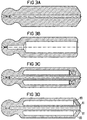
- the Cover can be done by spin welding, as shown in Fig. 3C and e.g. out DE 23 64 725 C2 is known to be applied to the main body.
- the Connection of the lid and the main body by means of rotary friction welding has the Disadvantage that due to the heat generated in the area of the weld Material hardening occurs. In order to retrofit the central hole allow annealing treatment is therefore necessary. Furthermore, removal of the Welding bead required after welding the cover and main body.
- the idea of the invention is based on the fact that the cover is on a plane, perpendicular to Longitudinal axis of the hollow piston aligned surface welded to the main body is that there is a radial weld over the entire area of the jacket, however extends only over such a peripheral region of the mandrel that does not extend to The scope of the central hole to be drilled is sufficient.
- the radial alignment of the weld seam ensures that both the outer Weld seam for connection to the shell of the main body as well as the inner one Weld seam for connection to the mandrel of the main body in one operation can be introduced, which leads to a considerable cost saving compared to leads known axial alignment of the welds.
- the depth of the weld in radial direction is dimensioned so that the area in which the central bore is to be introduced, is not covered by the weld seam. The central hole can therefore immediately after the welding operation without a previous annealing operation be introduced.
- the cover has an annular space of the main body opposite recess to the lateral deflection of the electron beam to prevent.
- FIG Axial piston machine described by way of example, in which the inventive Hollow pistons are used.
- the invention is not based on Axial piston machines limited. Rather, the hollow pistons according to the invention can different piston machines are used.
- the axial piston machine 1 shown in FIG. 2 is of swash plate construction adjustable displacement and executed in a known manner as essential components a hollow cylindrical housing 2, one attached to the housing 1 Terminal block 3, a swash plate 4, a control body 5, a drive shaft 6, a Cylinder drum 7 in which the cylinder bores 8, 9 are radially evenly distributed are arranged.
- the hollow pistons 10, 11 are displaceable in the cylinder bores 8, 9 arranged, which are formed in the embodiment as ball heads 12, 13 Rod ends of the hollow pistons 10, 11 on the swash plate 4 via sliding shoes 14, 15 support.
- An actuating device 17 accommodated in a bulge 16 of the housing 2 engages via an arm 18 extending in the direction of the connection block 3 on the Swashplate 4 and serves to pivot the same by one to the pivoting direction vertical swivel axis.
- the control body 5 is on the inner surface of the housing facing the Terminal blocks 3 attached and with two through openings in the form of kidney-shaped control slots 19, 20 provided via a pressure channel 21 or Suction channel 22 in the connection block 3 to a pressure or suction line, not shown are connected.
- the spherical one facing the housing interior Control surface of the control body 5 serves as a bearing surface for the cylinder drum 7.
- the drive shaft 6 protrudes through a through hole in the housing end wall 23 in the Housing 2 and is by means of a bearing 24 in this through hole and mounted rotatably in the connection block 3 by means of a further bearing 25.
- the Cylinder drum 7 is non-rotatably connected to drive shaft 6 by means of a keyway connection 26 connected.
- the cylinder bores are provided with orifices 27, 28 on the same Pitch circle as the control slots 19, 20 of the control body 5 open out.
- Cylinder bores 8, 9 each have a bushing 29, 30 inserted.
- Each slide shoe 14, 15 is on the sliding plate 31 of the swash plate 4 facing sliding surface with one each Not shown pressure bag provided, each via a through hole 32, 33 in Slide shoe 14, 15 on a stepped, axial through channel 34, 35 in the associated Pistons 10, 11 connected and in this way with the piston 10, 11 in the Cylinder bore 8, 9 delimited working space of the cylinder is connected.
- In each axial through channel 34, 35 is in the area of the associated ball head 12, 13 Choke trained.
- the present invention relates to a further development on the hollow pistons 10, 11.
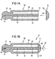
- the hollow piston 10 consists of a Main body 40 and a cover 41 which can be welded to the main body 40
- Main body 40 has a spherical head 12 in the exemplary embodiment Rod end open with a ball head bore 42 and throttle point 43.
- the ball head 12 is integrally formed on an end wall 44. From the side remote from the ball head 12 the end wall 44 extends with a central mandrel 45 and a central mandrel 45 Distance enclosing jacket 46.
- the between the cylindrical mandrel 45 and The annular space 47 which is formed in the hollow cylindrical jacket 46 is covered by the cover 41 closed, as shown in Fig. 1B.
- the cover 41 has a from FIG Detail better recognizable ring-shaped recess 48, which after placing the Cover 41 on the main body 40 opposite the annular space 47.
- the cover 41 and the main body 40 each have a plane End face 50, 51, which in the assembled state of cover 41 and main body 40 lie together.
- the flat surfaces 50 and 51 are perpendicular to the longitudinal axis 52 of the hollow piston 10 aligned.
- cover 41 and the main body 40 are preferred welded together in the radial direction by means of electron beam welding.
- To main body 40 and cover 41 are synchronously at the same rotational speed around the Longitudinal axis 52 of hollow piston 10 is set in rotation, as indicated by arrow 53 in 1B is indicated.
- the interface between the cover 41 and the main body 40 1B does not become an electron beam indicated by arrow 54 in FIG. 1B exposed electron beam welding system exposed.
- the intensity of the electron beam is regulated in such a way that the weld seam is a predetermined distance from the central longitudinal axis 52 of the Hollow piston 10 reached, which is larger than the diameter of another Operation to be introduced central bore 49.
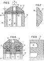
- This ensures that the Weld seam recesses that central area of the mandrel 45 through which in one further operation, the central bore 49 must be drilled through. This is essential, because with the heating during the welding process a hardening of the Material goes hand in hand, which is undone by an additional annealing operation should be. Since according to the procedure of the present invention However, the intensity and duration of the electron radiation is chosen so that that for the Central bore 49 required central area is not covered by the weld seam 82, this additional annealing operation is saved.
- Fig. 4B The state after welding is shown in Fig. 4B.
- the welding process creates massive, relatively hard welding beads that are removed on the outside Need to become. Only now can the contour of the hollow piston 10 be removed from each other welded blanks are worked out. Before introducing the Central bore 49, however, an additional annealing operation is required in order to Rotary friction welding soften hardened material areas for machining.
- the procedure according to the invention has several advantages. So can both the annealing operation and the reworking of the welding beads are eliminated. Furthermore, the cover 41 and the main body 40 can already have their final contour be processed before the welding operation. A support disc 71 for centering the Mandrel 45 during the welding operation is not required, which is the cost significantly reduced.
- the inner diameter D of the weld 82 is indeed smaller than the diameter of the mandrel 45, but larger than the diameter d that in the Mandrel 45 is to be introduced central bore 49.
- the periphery of the Mandrel 45, but not the area of the central bore 49, from the weld seam 82 detected.
- FIGS. 7 and 8 show this the lid 41 in an enlarged view
- Fig. 8 the blank for production of the lid 41 for the rotary friction welding process.
- the lid 41 of the Hollow piston according to the invention only an annular recess 48 of shallow depth is to be incorporated, which may even be omitted
- the blank cover for the Rotary friction welding methods have a relatively deep ring bore 72.
- the depth of the ring bore 72 is both the material removal during the Rotary friction welding process as well as the expansion of the resulting Sweaty fat to be considered.
- the structure of the lid 41 for the In contrast, hollow piston 10 according to the invention is much simpler.
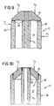
- FIGS trained hollow piston compared to a hollow piston with axially designed Electron beam welds described in Fig. 3D.
- Fig. 9 shows a section through the hollow piston according to the invention.
- the pair of forces F 2 shows that the compressive forces acting on the hollow piston 10 of the working medium located in the working cylinders 8, 9 act in a vertical direction on the weld seam 82.
- the pressure load F 2 of the piston acts parallel to the direction of the weld seams, which results in shear stress on the weld seams 60, 61. Compared to the design according to the invention, this leads to greater stress on the weld seams and can cause the weld seams to break prematurely.
- FIG. 9 also shows that the force pair F 1 acting on the running surface 83 of the hollow piston 10 does not act on the cover 41, since this is set back in the radial direction with respect to the running surfaces 83.
- the weld seams 82 are therefore not subjected to shear forces during operation.
- the invention is not limited to the illustrated embodiment. Rather are a variety of hollow piston configurations conceivable in which the invention Radial welding process can be applied.
Landscapes
- Engineering & Computer Science (AREA)
- Mechanical Engineering (AREA)
- General Engineering & Computer Science (AREA)
- Pistons, Piston Rings, And Cylinders (AREA)
Claims (8)
- Piston creux (10) pour une machine à piston (1) ayant un corps principal (40) qui comprend une broche centrale (45) avec un perçage central (49) traversant centralement la broche (45), la broche s'étendant à partir d'une paroi frontale (44) portant une tête d'articulation (12) du côté opposé de la paroi frontale (44) par rapport à la tête d'articulation, le corps principal comprenant en outre une enveloppe (46) entourant avec un espace la broche centrale (45) sur toute sa longueur, l'espace annulaire (47) ainsi formé entre la broche (45) et l'enveloppe (46) du corps principal (40) étant fermé par un couvercle (41) soudé avec la broche (45) et l'enveloppe (46), caractérisé en ce que le couvercle (41) est soudé au corps principal (40) selon une surface (50, 51) plane orientée perpendiculairement à l'axe longitudinal (52) du piston creux, de telle sorte qu'une soudure radiale (82) s'étend sur toute la zone de l'enveloppe (46) et uniquement sur une zone périphérique de la broche (45) qui n'atteint pas le pourtour du perçage central (49).
- Piston creux (10) pour une machine à piston (1) ayant un corps principal (40) qui comprend une broche centrale (45) formant une seule pièce avec une tête d'articulation, avec un perçage central (49) traversant centralement la broche (45), la broche s'étendant à partir d'une paroi frontale (44) portant la tête d'articulation (12) du côté opposé de la paroi frontale (44) par rapport à la tête d'articulation, le corps principal comprenant en outre une enveloppe (46) entourant avec un espace la broche centrale (45), l'espace annulaire (47) ainsi formé entre la broche (45) et l'enveloppe (46) du corps principal (40) étant fermé par un couvercle (41) soudé avec la broche (45) et l'enveloppe (46), caractérisé en ce que le couvercle (41) est soudé au corps principal (40) selon une surface (50, 51) plane orientée perpendiculairement à l'axe longitudinal (52) du piston creux, de telle sorte que une soudure radiale (82) s'étend sur toute la zone de l'enveloppe (46) et uniquement sur une zone périphérique de la broche (45) qui n'atteint pas le pourtour du perçage central (49).
- Piston creux selon la revendication 1 ou 2, caractérisé en ce que la soudure (82) est décalée vers l'axe longitudinal (52) central du piston par rapport à la périphérie externe de l'enveloppe (46), de façon à ce que le couvercle (41) présente un diamètre plus petit que la périphérie extérieure de l'enveloppe (46) du corps principal (40).
- Piston creux selon l'une des revendications 1 à 3, caractérisé en ce que le couvercle (41) comprend un évidement (48) s'étendant en face de l'espace annulaire (47) du corps principal (40).
- Piston creux selon l'une des revendications 1 à 4, caractérisé en ce que le couvercle (41) et le corps principal (40) sont soudés entre eux par soudage par bombardement électronique.
- Piston creux selon l'une des revendications 1 à 5, caractérisé en ce que le perçage central (49) traverse au moins en partie le disque frontal (44) et la tête d'articulation (12).
- Procédé de fabrication d'un piston creux (10) selon l'une des revendications 1 à 6 avec les étapes de procédé suivantes :fabrication du corps principal (40) et du couvercle (41),alignement axial du couvercle (41) par rapport à l'axe longitudinal (52) du corps principal (40) et assemblage du corps principal (40) et du couvercle (41),rotation synchrone du corps principal (40) et du couvercle (41),soudage du couvercle et du corps principal, dans lequel la surface de séparation (50, 51) du couvercle (41) et du corps principal (40), pendant la rotation, est exposée à un bombardement électronique radial orienté perpendiculairement à l'axe longitudinal (52) du piston creux (10),réglage de l'intensité du bombardement électronique, de façon à ce que la soudure (82) arrive à une distance (D/2) radiale prédéterminée de l'axe longitudinal (49) du piston creux (10), qui est plus petite que le rayon de la broche (45) et plus grande que le rayon (d/2) du perçage central (49) à réaliser, etréalisation, dans la broche (47) du corps principal (40), d'un perçage central traversant le couvercle (41).
- Procédé selon la revendication 7, caractérisé en ce que l'intensité et la durée du bombardement électronique sont choisies de telle sorte qu'aucun échauffement durcissant la matière ne se produise dans la zone du perçage central (49) à réaliser.
Applications Claiming Priority (2)
| Application Number | Priority Date | Filing Date | Title |
|---|---|---|---|
| DE19620167A DE19620167C2 (de) | 1996-05-20 | 1996-05-20 | Hohlkolben mit radial verschweißtem Deckel |
| DE19620167 | 1996-05-20 |
Publications (2)
| Publication Number | Publication Date |
|---|---|
| EP0808988A1 EP0808988A1 (fr) | 1997-11-26 |
| EP0808988B1 true EP0808988B1 (fr) | 2001-12-19 |
Family
ID=7794738
Family Applications (1)
| Application Number | Title | Priority Date | Filing Date |
|---|---|---|---|
| EP97106176A Expired - Lifetime EP0808988B1 (fr) | 1996-05-20 | 1997-04-15 | Piston creux avec un fond soudé radialement |
Country Status (2)
| Country | Link |
|---|---|
| EP (1) | EP0808988B1 (fr) |
| DE (2) | DE19620167C2 (fr) |
Cited By (1)
| Publication number | Priority date | Publication date | Assignee | Title |
|---|---|---|---|---|
| CN102814629A (zh) * | 2011-06-10 | 2012-12-12 | 罗伯特·博世有限公司 | 用于制造活塞的方法和用于活塞机的活塞 |
Families Citing this family (20)
| Publication number | Priority date | Publication date | Assignee | Title |
|---|---|---|---|---|
| JP2000038987A (ja) * | 1998-05-20 | 2000-02-08 | Toyota Autom Loom Works Ltd | 圧縮機のピストンの製造方法 |
| US6266878B1 (en) * | 1999-02-02 | 2001-07-31 | Amcast Industrial Corporation | Process for producing variable displacement compressor pistons having hollow piston bodies and integral actuator rods |
| DE19934217A1 (de) * | 1999-07-21 | 2001-02-01 | Brueninghaus Hydromatik Gmbh | Kolbenanordnung für eine Kolbenmaschine |
| DE19934216A1 (de) * | 1999-07-21 | 2001-02-01 | Brueninghaus Hydromatik Gmbh | Hohlkolben für eine Kolbenmaschine und Verfahren zum Herstellen eines Hohlkolbens |
| DE19938046A1 (de) * | 1999-08-12 | 2001-03-08 | Brueninghaus Hydromatik Gmbh | Hohlkolben für eine Kolbenmaschine und Verfahren zum Herstellen eines Hohlkolbens |
| JP3777942B2 (ja) * | 2000-03-15 | 2006-05-24 | 株式会社豊田自動織機 | 圧縮機用中空ピストンの製造方法 |
| DE10206728B4 (de) * | 2002-02-18 | 2006-08-24 | Brueninghaus Hydromatik Gmbh | Hohlkolben und Verfahren zu dessen Herstellung durch Sintern |
| US6703577B2 (en) * | 2002-06-10 | 2004-03-09 | Sauer-Danfoss Inc. | Method of making closed cavity pistons |
| DE10306792B4 (de) * | 2003-01-23 | 2007-03-22 | Valeo Compressor Europe Gmbh | Kolben, insbesondere für einen Axialkolben-Verdichter, und Verfahren zur Herstellung desselben |
| DE102005023367A1 (de) | 2005-05-20 | 2006-11-23 | Robert Bosch Gmbh | Zyklusbasiertes zeitgesteuertes Kommunikationssystem, Teilnehmer des Kommunikationssystems und Verfahren zur Datenübertragung zwischen Teilnehmern des Kommunikationssystems |
| DE102006060015B4 (de) * | 2006-12-19 | 2025-07-10 | Robert Bosch Gmbh | Hohlkolben für eine Axialkolbenmaschine |
| CN102865221A (zh) * | 2012-10-07 | 2013-01-09 | 四川省宜宾普什驱动有限责任公司 | 一种空心柱塞 |
| JP5981877B2 (ja) * | 2013-04-26 | 2016-08-31 | 川崎重工業株式会社 | 液圧回転機が備えるピストン及び液圧回転機 |
| DE102013208439A1 (de) | 2013-05-08 | 2014-11-13 | Robert Bosch Gmbh | Hohlkolben für eine hydrostatische Kolbenmaschine |
| DE102013008677A1 (de) * | 2013-05-22 | 2014-11-27 | Hydac Drive Center Gmbh | Hydropumpe und Kolben für eine solche Hydropumpe |
| WO2014187512A1 (fr) | 2013-05-22 | 2014-11-27 | Hydac Drive Center Gmbh | Pompe à pistons axiaux de type à plateau inclinable |
| DE102013211888A1 (de) | 2013-06-24 | 2014-12-24 | Robert Bosch Gmbh | Hohlkolben für eine Schrägscheibenmaschine und Schrägscheibenmaschine |
| DE102013211893A1 (de) | 2013-06-24 | 2014-12-24 | Robert Bosch Gmbh | Hohlkolben für eine Schrägscheibenmaschine und Schrägscheibenmaschine |
| CN105889059B (zh) * | 2016-05-31 | 2018-07-03 | 宁波派锐森液压有限公司 | 一种中空柱塞加工工艺 |
| JP7228994B2 (ja) * | 2018-11-15 | 2023-02-27 | 株式会社小松製作所 | ピストン及び油圧ポンプ・モータ |
Family Cites Families (9)
| Publication number | Priority date | Publication date | Assignee | Title |
|---|---|---|---|---|
| US3319575A (en) * | 1965-06-14 | 1967-05-16 | Sundstrand Corp | Piston |
| FR2148685A5 (fr) * | 1971-07-30 | 1973-03-23 | Coussinets Ste Indle | |
| DE2364725C2 (de) * | 1973-12-27 | 1985-12-12 | Sundstrand Corp., 61101 Rockford, Ill. | Verfahren zur Herstellung eines Kolbens |
| DE2653868A1 (de) * | 1976-11-26 | 1978-06-01 | Linde Ag | Hohlkolben fuer eine hydrostatische kolbenmaschine und verfahren zu dessen herstellung |
| DE2653867A1 (de) * | 1976-11-26 | 1978-06-01 | Linde Ag | Hohlkolben und verfahren zu dessen herstellung |
| DE3304903A1 (de) * | 1983-02-12 | 1984-08-16 | Alfred Teves Gmbh, 6000 Frankfurt | Kolben zur hydraulischen und/oder mechanischen kraftuebertragung auf ein zu beaufschlagendes bauteil, insbesondere auf die bremsbacken einer scheibenbremse |
| DE3602651C2 (de) * | 1986-01-29 | 1995-03-30 | Linde Ag | Hohlkolben für eine Axialkolbenmaschine und Verfahren zu dessen Herstellung |
| US5265331A (en) * | 1992-01-16 | 1993-11-30 | Caterpillar Inc. | Method of manufacturing a piston for an axial piston fluid translating device |
| DE4423023C2 (de) * | 1994-06-30 | 1998-07-09 | Brueninghaus Hydromatik Gmbh | Axialkolbenmaschine mit einem Kühlkreislauf für die Zylinder und Kolben |
-
1996
- 1996-05-20 DE DE19620167A patent/DE19620167C2/de not_active Expired - Fee Related
-
1997
- 1997-04-15 EP EP97106176A patent/EP0808988B1/fr not_active Expired - Lifetime
- 1997-04-15 DE DE59705843T patent/DE59705843D1/de not_active Expired - Fee Related
Cited By (1)
| Publication number | Priority date | Publication date | Assignee | Title |
|---|---|---|---|---|
| CN102814629A (zh) * | 2011-06-10 | 2012-12-12 | 罗伯特·博世有限公司 | 用于制造活塞的方法和用于活塞机的活塞 |
Also Published As
| Publication number | Publication date |
|---|---|
| EP0808988A1 (fr) | 1997-11-26 |
| DE59705843D1 (de) | 2002-01-31 |
| DE19620167C1 (de) | 1997-03-13 |
| DE19620167C2 (de) | 1998-11-12 |
Similar Documents
| Publication | Publication Date | Title |
|---|---|---|
| EP0808988B1 (fr) | Piston creux avec un fond soudé radialement | |
| DE2756878A1 (de) | Kolben, insbesondere fuer brennkraftmaschinen, wie hochgeschwindigkeits-dieselmotoren sowie verfahren zu seiner herstellung | |
| DE10300070A1 (de) | Axialkolbenmaschine, Rückzugplatte und Verfahren zum Herstellen einer Rückzugplatte | |
| EP1664488B1 (fr) | Piston creux destine a une machine a pistons et procede de fabrication d'un piston creux | |
| EP0963506B1 (fr) | Piston pour machine hydrostatique | |
| DE19934218C2 (de) | Verfahren zum Herstellen einer Kugelgelenkverbindung zwischen einem Gleitschuh und einem Kolben und Axialkolbenmaschine mit einer Kugelgelenkverbindung | |
| DE4301126C2 (de) | Verfahren zum Montieren einer Laufbuchse in einem Grundkörper einer hydraulischen Maschine und hydraulische Maschine | |
| DE3828131C2 (fr) | ||
| EP1378628B1 (fr) | Piston creux pour machine à piston et procédé pour fabriquer un piston creux | |
| EP1248906A2 (fr) | Ensemble a piston pour machine a piston | |
| EP1427914A1 (fr) | Machine hydrostatique chemises de cylindres compens es | |
| EP1590568B1 (fr) | Piston creux pour une machine a piston et procede de production d'un piston creux | |
| EP3676495B1 (fr) | Procédé de fabrication, ébauche de piston, piston et machine à pistons axiaux ayant ce piston | |
| DE10102989C2 (de) | Fügeverfahren für eine Kugelgelenkverbindung | |
| DE19859199A1 (de) | Gelenkverbindung zwischen einem Schaft und einem Gleitschuh einer Kolbenmaschine und Verfahren zum Herstellen der Gelenkverbindung | |
| EP1561031B1 (fr) | Moteur a pistons axiaux, plateau oscillant et procede de fabrication d'un plateau oscillant | |
| DE3822329C2 (fr) | ||
| DE10157248A1 (de) | Hydrostatische Maschine mit kompensierten Laufbuchsen | |
| EP0943798A2 (fr) | Machine axiale à pistons avec compensation hydrostatique des alésages des cylindres | |
| DE19815614A1 (de) | Axialkolbenmaschine mit hydrostatischer Entlastung der Zylinderbohrungen | |
| DE102015222386A1 (de) | Verfahren zur Fertigung einer kalottenförmigen Ausnehmung in einer Triebwelle, Triebwelle mit der Ausnehmung, und hydrostatische Axialkolbenmaschine mit der Triebwelle | |
| DE19641733C2 (de) | Hydrodynamischer Wandler mit Vertiefungen für Schaufeln | |
| DE10246699A1 (de) | Gleitschuh mit formschlüssig verbundenem Gleitteil und Stützkörper | |
| DE102018131768A1 (de) | Verfahren zur Herstellung einer Trommel einer Axialkolbenmaschine | |
| DE102010052561A1 (de) | Verfahren zur Anbindung von Kolben an eine Rotorplatte, Triebwelle und Hydraulikmaschine |
Legal Events
| Date | Code | Title | Description |
|---|---|---|---|
| PUAI | Public reference made under article 153(3) epc to a published international application that has entered the european phase |
Free format text: ORIGINAL CODE: 0009012 |
|
| AK | Designated contracting states |
Kind code of ref document: A1 Designated state(s): DE FR GB IT SE |
|
| 17P | Request for examination filed |
Effective date: 19971104 |
|
| 17Q | First examination report despatched |
Effective date: 20000817 |
|
| GRAG | Despatch of communication of intention to grant |
Free format text: ORIGINAL CODE: EPIDOS AGRA |
|
| GRAG | Despatch of communication of intention to grant |
Free format text: ORIGINAL CODE: EPIDOS AGRA |
|
| GRAH | Despatch of communication of intention to grant a patent |
Free format text: ORIGINAL CODE: EPIDOS IGRA |
|
| GRAH | Despatch of communication of intention to grant a patent |
Free format text: ORIGINAL CODE: EPIDOS IGRA |
|
| GRAA | (expected) grant |
Free format text: ORIGINAL CODE: 0009210 |
|
| AK | Designated contracting states |
Kind code of ref document: B1 Designated state(s): DE FR GB IT SE |
|
| REG | Reference to a national code |
Ref country code: GB Ref legal event code: IF02 |
|
| REF | Corresponds to: |
Ref document number: 59705843 Country of ref document: DE Date of ref document: 20020131 |
|
| GBT | Gb: translation of ep patent filed (gb section 77(6)(a)/1977) |
Effective date: 20020315 |
|
| ET | Fr: translation filed | ||
| PLBE | No opposition filed within time limit |
Free format text: ORIGINAL CODE: 0009261 |
|
| STAA | Information on the status of an ep patent application or granted ep patent |
Free format text: STATUS: NO OPPOSITION FILED WITHIN TIME LIMIT |
|
| 26N | No opposition filed | ||
| PGFP | Annual fee paid to national office [announced via postgrant information from national office to epo] |
Ref country code: DE Payment date: 20080418 Year of fee payment: 12 |
|
| PGFP | Annual fee paid to national office [announced via postgrant information from national office to epo] |
Ref country code: SE Payment date: 20090427 Year of fee payment: 13 Ref country code: IT Payment date: 20090427 Year of fee payment: 13 Ref country code: FR Payment date: 20090420 Year of fee payment: 13 |
|
| PGFP | Annual fee paid to national office [announced via postgrant information from national office to epo] |
Ref country code: GB Payment date: 20090424 Year of fee payment: 13 |
|
| PG25 | Lapsed in a contracting state [announced via postgrant information from national office to epo] |
Ref country code: DE Free format text: LAPSE BECAUSE OF NON-PAYMENT OF DUE FEES Effective date: 20091103 |
|
| EUG | Se: european patent has lapsed | ||
| GBPC | Gb: european patent ceased through non-payment of renewal fee |
Effective date: 20100415 |
|
| REG | Reference to a national code |
Ref country code: FR Ref legal event code: ST Effective date: 20101230 |
|
| PG25 | Lapsed in a contracting state [announced via postgrant information from national office to epo] |
Ref country code: GB Free format text: LAPSE BECAUSE OF NON-PAYMENT OF DUE FEES Effective date: 20100415 Ref country code: IT Free format text: LAPSE BECAUSE OF NON-PAYMENT OF DUE FEES Effective date: 20100415 |
|
| PG25 | Lapsed in a contracting state [announced via postgrant information from national office to epo] |
Ref country code: FR Free format text: LAPSE BECAUSE OF NON-PAYMENT OF DUE FEES Effective date: 20100430 |
|
| PG25 | Lapsed in a contracting state [announced via postgrant information from national office to epo] |
Ref country code: SE Free format text: LAPSE BECAUSE OF NON-PAYMENT OF DUE FEES Effective date: 20100416 |