EP0808988A1 - Piston creux avec un fond soudé radialement - Google Patents
Piston creux avec un fond soudé radialement Download PDFInfo
- Publication number
- EP0808988A1 EP0808988A1 EP97106176A EP97106176A EP0808988A1 EP 0808988 A1 EP0808988 A1 EP 0808988A1 EP 97106176 A EP97106176 A EP 97106176A EP 97106176 A EP97106176 A EP 97106176A EP 0808988 A1 EP0808988 A1 EP 0808988A1
- Authority
- EP
- European Patent Office
- Prior art keywords
- main body
- cover
- hollow piston
- mandrel
- central bore
- Prior art date
- Legal status (The legal status is an assumption and is not a legal conclusion. Google has not performed a legal analysis and makes no representation as to the accuracy of the status listed.)
- Granted
Links
- 238000000034 method Methods 0.000 claims abstract description 28
- 238000004519 manufacturing process Methods 0.000 claims abstract description 8
- 230000002093 peripheral effect Effects 0.000 claims abstract description 3
- 241000309551 Arthraxon hispidus Species 0.000 claims abstract 5
- 238000003466 welding Methods 0.000 claims description 50
- 238000010894 electron beam technology Methods 0.000 claims description 11
- 230000000149 penetrating effect Effects 0.000 claims description 3
- 238000010438 heat treatment Methods 0.000 claims description 2
- 230000005855 radiation Effects 0.000 claims description 2
- 230000001105 regulatory effect Effects 0.000 claims description 2
- 238000005304 joining Methods 0.000 claims 1
- 230000001360 synchronised effect Effects 0.000 claims 1
- 238000011161 development Methods 0.000 abstract description 3
- 238000000137 annealing Methods 0.000 description 7
- 239000000463 material Substances 0.000 description 6
- 239000011324 bead Substances 0.000 description 4
- 230000018109 developmental process Effects 0.000 description 2
- 239000007787 solid Substances 0.000 description 2
- 229910000831 Steel Inorganic materials 0.000 description 1
- 230000006866 deterioration Effects 0.000 description 1
- 238000006073 displacement reaction Methods 0.000 description 1
- 239000012530 fluid Substances 0.000 description 1
- 238000003754 machining Methods 0.000 description 1
- 238000003825 pressing Methods 0.000 description 1
- 239000010959 steel Substances 0.000 description 1
Images


Classifications
-
- B—PERFORMING OPERATIONS; TRANSPORTING
- B23—MACHINE TOOLS; METAL-WORKING NOT OTHERWISE PROVIDED FOR
- B23P—METAL-WORKING NOT OTHERWISE PROVIDED FOR; COMBINED OPERATIONS; UNIVERSAL MACHINE TOOLS
- B23P15/00—Making specific metal objects by operations not covered by a single other subclass or a group in this subclass
- B23P15/10—Making specific metal objects by operations not covered by a single other subclass or a group in this subclass pistons
-
- F—MECHANICAL ENGINEERING; LIGHTING; HEATING; WEAPONS; BLASTING
- F01—MACHINES OR ENGINES IN GENERAL; ENGINE PLANTS IN GENERAL; STEAM ENGINES
- F01B—MACHINES OR ENGINES, IN GENERAL OR OF POSITIVE-DISPLACEMENT TYPE, e.g. STEAM ENGINES
- F01B3/00—Reciprocating-piston machines or engines with cylinder axes coaxial with, or parallel or inclined to, main shaft axis
- F01B3/0082—Details
- F01B3/0085—Pistons
-
- F—MECHANICAL ENGINEERING; LIGHTING; HEATING; WEAPONS; BLASTING
- F04—POSITIVE - DISPLACEMENT MACHINES FOR LIQUIDS; PUMPS FOR LIQUIDS OR ELASTIC FLUIDS
- F04B—POSITIVE-DISPLACEMENT MACHINES FOR LIQUIDS; PUMPS
- F04B1/00—Multi-cylinder machines or pumps characterised by number or arrangement of cylinders
- F04B1/12—Multi-cylinder machines or pumps characterised by number or arrangement of cylinders having cylinder axes coaxial with, or parallel or inclined to, main shaft axis
- F04B1/122—Details or component parts, e.g. valves, sealings or lubrication means
- F04B1/124—Pistons
Definitions
- the invention relates to a hollow piston for a piston machine, in particular an axial piston machine, and a method for producing such a hollow piston.
- the solid pistons usually used in axial piston machines set limits to operation at higher speeds. At higher speeds, strength problems arise for the cylinders due to the large centrifugal forces and for the piston restraint device due to the large inertial forces, as well as thermal problems on the contact surfaces between the pistons and cylinders due to the frictional forces resulting from the centrifugal forces. Hollow pistons are therefore used to operate axial piston machines at increased speed.
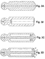
- Hollow pistons are already known in various designs. The known designs are briefly described below with reference to Figures 3B to 3D.
- the design of the hollow-bore pistons (FIG. 3B) has the disadvantage that the cavity created in the piston is filled with fluid. As a result, this volume range is compressed and relaxed again with each piston stroke, which leads to a deterioration in the efficiency.
- the cover can be applied to the main body by rotary friction welding, as is shown in FIG. 3C and is known, for example, from DE 23 64 725 C2.
- the connection of the cover and the main body by means of rotary welding has the disadvantage, however, that material hardening occurs in the area of the weld due to the heat generated. An annealing treatment is therefore necessary to enable the central bore to be drilled subsequently. Furthermore, removal of the welding bead after welding the cover and main body is necessary.
- the idea of the invention is based on the fact that the cover is welded to the main body on a planar surface oriented perpendicular to the longitudinal axis of the hollow piston so that a radial weld seam extends over the entire area of the casing but only over such a peripheral area of the mandrel that does not extends to the extent of the central bore to be drilled.
- the radial alignment of the weld seam ensures that both the outer weld seam for connection to the jacket of the main body and the inner weld seam for connection to the mandrel of the main body can be introduced in one operation, which results in a considerable cost saving compared to leads known axial alignment of the welds.
- the depth of the weld seam in the radial direction is dimensioned such that the area in which the central bore is to be drilled is not covered by the weld seam. The central bore can therefore be drilled immediately after the welding operation without a previous annealing operation.
- Claims 2 to 5 contain advantageous developments of the hollow piston according to the invention.
- the cover is formed with a smaller diameter than the outer circumference of the casing of the main body, it is achieved according to claim 2 that the weld seam is set back with respect to the outer circumference of the casing. This has the advantage that the weld seam does not touch the running surface of the cylinder and therefore there is no need to rework the weld seam.
- the cover has a recess opposite the annular space of the main body in order to prevent the lateral deflection of the electron beam.
- Electron beam welding is particularly suitable for connecting the cover and main body according to the invention.
- the weld seam is only made so deep that the area of the central bore to be subsequently drilled into the cover and the mandrel of the main body is not covered.
- the central bore can therefore be introduced without prior annealing, since the material in the area of the central bore is not hardened by the welding process.
- an axial piston machine in which the hollow pistons according to the invention are used will first be described by way of example with reference to FIG. 2.
- the invention is not limited to axial piston machines. Rather, the hollow pistons according to the invention can be used in different piston machines.
- the axial piston machine 1 shown in FIG. 2 is designed in a swashplate design with an adjustable displacement volume and comprises, in a known manner, as essential components a hollow cylindrical housing 2, a connection block 3 fastened to the housing 1, a swashplate 4, a control body 5, a drive shaft 6, and a cylinder drum 7, in which the cylinder bores 8, 9 are arranged radially evenly distributed.
- the hollow pistons 10, 11 are arranged displaceably in the cylinder bores 8, 9, the articulated heads of the hollow pistons 10, 11, which are designed as ball heads 12, 13 in the exemplary embodiment, being supported on the swash plate 4 via sliding shoes 14, 15.
- the control body 5 is fastened to the inner surface of the connection block 3 facing the housing interior and is provided with two through openings in the form of kidney-shaped control slots 19, 20, which are connected via a pressure channel 21 or suction channel 22 in the connection block 3 to a pressure or not shown Suction line are connected.
- the spherical control surface of the control body 5 facing the housing interior serves as a bearing surface for the cylinder drum 7.
- the drive shaft 6 projects through a through hole in the housing end wall 23 into the housing 2 and is rotatably supported by means of a bearing 24 in this through hole and by means of a further bearing 25 in the connection block 3.
- the cylinder drum 7 is non-rotatably connected to the drive shaft 6 by means of a keyway connection 26.
- the cylinder bores are provided with outlet channels 27, 28 which open out on the same pitch circle as the control slots 19, 20 of the control body 5.
- a bushing 29, 30 is inserted into each of the cylinder bores 8, 9.
- Each slide shoe 14, 15 is provided on its slide surface facing the slide plate 31 of the swash plate 4, each with a pressure pocket, not shown, which has a through bore 32, 33 in the slide shoe 14, 15 on a stepped, axial through-channel 34, 35 in the associated piston 10 , 11 and is connected in this way to the working space of the cylinder defined by the piston 10, 11 in the cylinder bore 8, 9.
- a throttle is formed in each axial through-channel 34, 35 in the area of the associated ball head 12, 13.
- the present invention relates to a further development on the hollow pistons 10, 11.
- FIGS. 1A and 1B A section through a hollow piston 10 designed according to the invention is shown in FIGS. 1A and 1B.
- the hollow piston 10 according to the invention consists of a Main body 40 and a cover 41 which can be welded to the main body 40.
- the main body 40 has an articulated head, which in the exemplary embodiment is designed as a ball head 12, with a ball head bore 42 and throttle point 43.
- the ball head 12 is integrally formed on an end wall 44.
- a central mandrel 45 and a jacket 46 enclosing the central mandrel 45 at a distance extends from the side of the end wall 44 remote from the spherical head 12.
- the annular space 47 formed between the cylindrical mandrel 45 and the hollow cylindrical jacket 46 is closed by the cover 41, as shown in Fig. 1B.
- the cover 41 has an annular recess 48 which can be seen better in detail in FIG. 7 and which, after the cover 41 has been placed on the main body 40, lies opposite the annular
- a central bore 49 penetrating the cover 41 and the mandrel 45 of the main body 40 is introduced into the hollow piston 10 and extends to the throttle point 43 in the ball head 12. In this way, a connection is created between the working volume of the cylinder bores 8, 9 and the through bores 32, 33 in the sliding blocks 14, 15.
- the cover 41 and the main body 40 each have a flat end face 50, 51, which in the assembled state of the cover 41 and main body 40 abut one another.
- the flat surfaces 50 and 51 are aligned perpendicular to the longitudinal axis 52 of the hollow piston 10.
- cover 41 and main body 40 After the cover 41 and main body 40 have been joined together, they are preferably welded to one another in the radial direction by means of electron steel welding.
- main body 40 and cover 41 are set in rotation synchronously at the same rotational speed about the longitudinal axis 52 of the hollow piston 10, as is indicated by the arrow 53 in FIG. 1B.
- the interface between the cover 41 and the main body 40 is exposed to an electron beam, indicated by the arrow 54 in FIG. 1B, of an electron beam welding system, not shown.
- a weld seam 82 which grows radially from the circumference in the direction of the central longitudinal axis 52, is formed at the interface between the cover 41 and the main body 40 and is formed uniformly over the entire circumference due to the rotation of the hollow piston 10.
- the intensity of the electron beam is regulated so that the weld seam reaches a predetermined distance from the central longitudinal axis 52 of the hollow piston 10, which is larger than the diameter of the central bore 49 to be made in a further operation.
- This ensures that the weld seam recesses that central area of the mandrel 45 through which the central bore 49 must be drilled in a further operation.
- This is essential since the heating during the welding process is accompanied by hardening of the material, which would have to be reversed by an additional annealing operation. Since, according to the procedure of the present invention, the intensity and duration of the electron radiation is selected such that the central area required for the central bore 49 is not covered by the weld seam 82, this additional annealing operation is saved.
- the two weld seams 60 and 61 in FIG. 3D have to be introduced in two separate work steps.
- Fig. 4B The state after welding is shown in Fig. 4B.
- the welding process creates massive, relatively hard welding beads that must be removed on the outside. Only now can the contour of the hollow piston 10 be worked out from the blanks welded together. Before the central bore 49 is introduced, however, an additional annealing operation is required in order to soften the material areas hardened during the rotary friction welding for the machining.
- the procedure according to the invention has several advantages. This means that both the annealing process and the reworking of the welding beads can be omitted. Furthermore, the cover 41 and the main body 40 can already be machined in their final contour before the welding operation. A support disk 71 for centering the mandrel 45 during the welding operation is not required, which considerably reduces the costs.
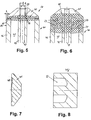
- FIGS. 5 and 6 the area of the heat affected zone, which can cause the material to harden, is compared for the welding method according to the invention (FIG. 5) and the known rotary friction welding method (FIG. 6). It is immediately apparent from the comparison that the heat-affected zone 80 of the radial welding method according to the invention shown in FIG. 5 has a much smaller expansion than the heat-affected zone 81 of the rotary friction welding method shown in FIG. 6.
- the inner diameter D of the weld seam 82 is smaller than the diameter of the mandrel 45, but larger than the diameter d of the central bore 49 to be made in the mandrel 45.
- the periphery of the mandrel 45, but not the region of the central bore 49, is covered by the weld seam 82.
- the weld seam 82 is set back in relation to the running zone 83 of the hollow piston 10 in the direction of the center of the hollow piston and thus does not touch the running surface of the associated cylinder bore 8, 9.
- the weld seam 82 therefore does not have to be reworked. Since the weld seam 82 lies outside the running zone 83 of the hollow piston 10, there are no different properties on the running surface 83, in particular no differences in hardness or shape deviations, as in the case of the rotary friction-welded design.
- FIG. 7 shows the cover 41 in an enlarged representation
- FIG. 8 shows the blank for producing the cover 41 for the rotary friction welding process.
- the cover 41 of the hollow piston according to the invention While in the cover 41 of the hollow piston according to the invention only an annular recess 48 of shallow depth has to be machined, which may even be omitted, the cover blank for the rotary friction welding process must have a relatively deep ring bore 72. When dimensioning the depth of the ring bore 72, both the material removal during the rotary friction welding process and the expansion of the welding bulge which arises in the process must be taken into account.
- the structure of the cover 41 for the hollow piston 10 according to the invention is, however, much simpler.
- Fig. 9 shows a section through the hollow piston according to the invention.
- the pair of forces F 2 illustrates that the compressive forces acting on the hollow piston 10 of the working medium located in the working cylinders 8, 9 act in a vertical direction on the weld seam 82.
- the pressure load F 2 of the piston acts parallel to the direction of the weld seams, which results in shear stress on the weld seams 60, 61. Compared to the design according to the invention, this leads to greater stress on the weld seams and can cause the weld seams to break prematurely.
- FIG. 9 also shows that the force pair F 1 acting on the running surface 83 of the hollow piston 10 does not act on the cover 41, since this is set back in the radial direction with respect to the running surfaces 83.
- the weld seams 82 are therefore not subjected to shear forces during operation.
- the invention is not limited to the illustrated embodiment. Rather, a large number of hollow piston configurations are conceivable, in which the radial welding method according to the invention can be used.
Landscapes
- Engineering & Computer Science (AREA)
- Mechanical Engineering (AREA)
- General Engineering & Computer Science (AREA)
- Pistons, Piston Rings, And Cylinders (AREA)
Applications Claiming Priority (2)
| Application Number | Priority Date | Filing Date | Title |
|---|---|---|---|
| DE19620167A DE19620167C2 (de) | 1996-05-20 | 1996-05-20 | Hohlkolben mit radial verschweißtem Deckel |
| DE19620167 | 1996-05-20 |
Publications (2)
| Publication Number | Publication Date |
|---|---|
| EP0808988A1 true EP0808988A1 (fr) | 1997-11-26 |
| EP0808988B1 EP0808988B1 (fr) | 2001-12-19 |
Family
ID=7794738
Family Applications (1)
| Application Number | Title | Priority Date | Filing Date |
|---|---|---|---|
| EP97106176A Expired - Lifetime EP0808988B1 (fr) | 1996-05-20 | 1997-04-15 | Piston creux avec un fond soudé radialement |
Country Status (2)
| Country | Link |
|---|---|
| EP (1) | EP0808988B1 (fr) |
| DE (2) | DE19620167C2 (fr) |
Cited By (2)
| Publication number | Priority date | Publication date | Assignee | Title |
|---|---|---|---|---|
| CN102865221A (zh) * | 2012-10-07 | 2013-01-09 | 四川省宜宾普什驱动有限责任公司 | 一种空心柱塞 |
| CN105889059A (zh) * | 2016-05-31 | 2016-08-24 | 宁波派锐森液压有限公司 | 一种中空柱塞及其加工工艺 |
Families Citing this family (19)
| Publication number | Priority date | Publication date | Assignee | Title |
|---|---|---|---|---|
| JP2000038987A (ja) * | 1998-05-20 | 2000-02-08 | Toyota Autom Loom Works Ltd | 圧縮機のピストンの製造方法 |
| US6266878B1 (en) * | 1999-02-02 | 2001-07-31 | Amcast Industrial Corporation | Process for producing variable displacement compressor pistons having hollow piston bodies and integral actuator rods |
| DE19934217A1 (de) * | 1999-07-21 | 2001-02-01 | Brueninghaus Hydromatik Gmbh | Kolbenanordnung für eine Kolbenmaschine |
| DE19934216A1 (de) * | 1999-07-21 | 2001-02-01 | Brueninghaus Hydromatik Gmbh | Hohlkolben für eine Kolbenmaschine und Verfahren zum Herstellen eines Hohlkolbens |
| DE19938046A1 (de) * | 1999-08-12 | 2001-03-08 | Brueninghaus Hydromatik Gmbh | Hohlkolben für eine Kolbenmaschine und Verfahren zum Herstellen eines Hohlkolbens |
| JP3777942B2 (ja) * | 2000-03-15 | 2006-05-24 | 株式会社豊田自動織機 | 圧縮機用中空ピストンの製造方法 |
| DE10206728B4 (de) * | 2002-02-18 | 2006-08-24 | Brueninghaus Hydromatik Gmbh | Hohlkolben und Verfahren zu dessen Herstellung durch Sintern |
| US6703577B2 (en) * | 2002-06-10 | 2004-03-09 | Sauer-Danfoss Inc. | Method of making closed cavity pistons |
| DE10306792B4 (de) * | 2003-01-23 | 2007-03-22 | Valeo Compressor Europe Gmbh | Kolben, insbesondere für einen Axialkolben-Verdichter, und Verfahren zur Herstellung desselben |
| DE102005023367A1 (de) | 2005-05-20 | 2006-11-23 | Robert Bosch Gmbh | Zyklusbasiertes zeitgesteuertes Kommunikationssystem, Teilnehmer des Kommunikationssystems und Verfahren zur Datenübertragung zwischen Teilnehmern des Kommunikationssystems |
| DE102006060015B4 (de) * | 2006-12-19 | 2025-07-10 | Robert Bosch Gmbh | Hohlkolben für eine Axialkolbenmaschine |
| DE102011103883A1 (de) * | 2011-06-10 | 2012-12-13 | Robert Bosch Gmbh | Verfahren zur Herstellung eines Kolbens und Kolben für eine Kolbenmaschine |
| JP5981877B2 (ja) * | 2013-04-26 | 2016-08-31 | 川崎重工業株式会社 | 液圧回転機が備えるピストン及び液圧回転機 |
| DE102013208439A1 (de) | 2013-05-08 | 2014-11-13 | Robert Bosch Gmbh | Hohlkolben für eine hydrostatische Kolbenmaschine |
| DE102013008677A1 (de) * | 2013-05-22 | 2014-11-27 | Hydac Drive Center Gmbh | Hydropumpe und Kolben für eine solche Hydropumpe |
| EP2999885B1 (fr) | 2013-05-22 | 2017-12-06 | Hydac Drive Center GmbH | Machine à piston axial du type à plateau en biais |
| DE102013211893A1 (de) | 2013-06-24 | 2014-12-24 | Robert Bosch Gmbh | Hohlkolben für eine Schrägscheibenmaschine und Schrägscheibenmaschine |
| DE102013211888A1 (de) | 2013-06-24 | 2014-12-24 | Robert Bosch Gmbh | Hohlkolben für eine Schrägscheibenmaschine und Schrägscheibenmaschine |
| JP7228994B2 (ja) | 2018-11-15 | 2023-02-27 | 株式会社小松製作所 | ピストン及び油圧ポンプ・モータ |
Citations (5)
| Publication number | Priority date | Publication date | Assignee | Title |
|---|---|---|---|---|
| US3319575A (en) * | 1965-06-14 | 1967-05-16 | Sundstrand Corp | Piston |
| GB1363347A (en) * | 1971-07-30 | 1974-08-14 | Ind Des Coussinets Soc | Pump barrels and methods of manufacturing the same |
| DE2653867A1 (de) * | 1976-11-26 | 1978-06-01 | Linde Ag | Hohlkolben und verfahren zu dessen herstellung |
| DE3602651A1 (de) * | 1986-01-29 | 1987-07-30 | Linde Ag | Hohlkolben fuer eine axialkolbenmaschine und verfahren zu dessen herstellung |
| US5265331A (en) * | 1992-01-16 | 1993-11-30 | Caterpillar Inc. | Method of manufacturing a piston for an axial piston fluid translating device |
Family Cites Families (4)
| Publication number | Priority date | Publication date | Assignee | Title |
|---|---|---|---|---|
| DE2364725C2 (de) * | 1973-12-27 | 1985-12-12 | Sundstrand Corp., 61101 Rockford, Ill. | Verfahren zur Herstellung eines Kolbens |
| DE2653868A1 (de) * | 1976-11-26 | 1978-06-01 | Linde Ag | Hohlkolben fuer eine hydrostatische kolbenmaschine und verfahren zu dessen herstellung |
| DE3304903A1 (de) * | 1983-02-12 | 1984-08-16 | Alfred Teves Gmbh, 6000 Frankfurt | Kolben zur hydraulischen und/oder mechanischen kraftuebertragung auf ein zu beaufschlagendes bauteil, insbesondere auf die bremsbacken einer scheibenbremse |
| DE4423023C2 (de) * | 1994-06-30 | 1998-07-09 | Brueninghaus Hydromatik Gmbh | Axialkolbenmaschine mit einem Kühlkreislauf für die Zylinder und Kolben |
-
1996
- 1996-05-20 DE DE19620167A patent/DE19620167C2/de not_active Expired - Fee Related
-
1997
- 1997-04-15 EP EP97106176A patent/EP0808988B1/fr not_active Expired - Lifetime
- 1997-04-15 DE DE59705843T patent/DE59705843D1/de not_active Expired - Fee Related
Patent Citations (5)
| Publication number | Priority date | Publication date | Assignee | Title |
|---|---|---|---|---|
| US3319575A (en) * | 1965-06-14 | 1967-05-16 | Sundstrand Corp | Piston |
| GB1363347A (en) * | 1971-07-30 | 1974-08-14 | Ind Des Coussinets Soc | Pump barrels and methods of manufacturing the same |
| DE2653867A1 (de) * | 1976-11-26 | 1978-06-01 | Linde Ag | Hohlkolben und verfahren zu dessen herstellung |
| DE3602651A1 (de) * | 1986-01-29 | 1987-07-30 | Linde Ag | Hohlkolben fuer eine axialkolbenmaschine und verfahren zu dessen herstellung |
| US5265331A (en) * | 1992-01-16 | 1993-11-30 | Caterpillar Inc. | Method of manufacturing a piston for an axial piston fluid translating device |
Cited By (3)
| Publication number | Priority date | Publication date | Assignee | Title |
|---|---|---|---|---|
| CN102865221A (zh) * | 2012-10-07 | 2013-01-09 | 四川省宜宾普什驱动有限责任公司 | 一种空心柱塞 |
| CN105889059A (zh) * | 2016-05-31 | 2016-08-24 | 宁波派锐森液压有限公司 | 一种中空柱塞及其加工工艺 |
| CN105889059B (zh) * | 2016-05-31 | 2018-07-03 | 宁波派锐森液压有限公司 | 一种中空柱塞加工工艺 |
Also Published As
| Publication number | Publication date |
|---|---|
| DE59705843D1 (de) | 2002-01-31 |
| EP0808988B1 (fr) | 2001-12-19 |
| DE19620167C2 (de) | 1998-11-12 |
| DE19620167C1 (de) | 1997-03-13 |
Similar Documents
| Publication | Publication Date | Title |
|---|---|---|
| DE19620167C1 (de) | Hohlkolben mit radial verschweißtem Deckel | |
| DE3886614T2 (de) | Torsionsschwingungsdämpfer mit einem gewalzten Gehäuse und anderen Verbesserungen. | |
| DE4311997A1 (de) | Hydraulikmotor | |
| DE10300070A1 (de) | Axialkolbenmaschine, Rückzugplatte und Verfahren zum Herstellen einer Rückzugplatte | |
| EP1664488B1 (fr) | Piston creux destine a une machine a pistons et procede de fabrication d'un piston creux | |
| DE19934218C2 (de) | Verfahren zum Herstellen einer Kugelgelenkverbindung zwischen einem Gleitschuh und einem Kolben und Axialkolbenmaschine mit einer Kugelgelenkverbindung | |
| EP0963506B1 (fr) | Piston pour machine hydrostatique | |
| DE3828131C2 (fr) | ||
| DE10251552B3 (de) | Axialkolbenmaschine und Steuerplatte für eine Axialkolbenmaschine | |
| DE19934217A1 (de) | Kolbenanordnung für eine Kolbenmaschine | |
| EP1427914A1 (fr) | Machine hydrostatique chemises de cylindres compens es | |
| EP1015162B1 (fr) | Procede et dispositif pour joindre des composants | |
| EP1336449A2 (fr) | Piston creux et procédé de sa fabrication par soudage, diffusion ou frittage | |
| DE10102989C2 (de) | Fügeverfahren für eine Kugelgelenkverbindung | |
| EP0252105B1 (fr) | Machine a piston axial | |
| EP3676495B1 (fr) | Procédé de fabrication, ébauche de piston, piston et machine à pistons axiaux ayant ce piston | |
| DE2005080A1 (de) | Drehschwingungsdämpfer und Verfahren zu seiner Herstellung | |
| DE102006030492B4 (de) | Verfahren zum Schleifen einer Kompressor-Kurbelwelle | |
| EP3928903A1 (fr) | Procédé de fabrication d'un segment de traitement doté d'une projection de particules de matériau dur sur les surfaces latérales du segment de traitement | |
| EP1336756A2 (fr) | Piston de pompe rempli de sphères creuses | |
| DE3822329C2 (fr) | ||
| DE2237418C2 (de) | Zylinderblock für Pumpen | |
| EP1561031A1 (fr) | Moteur a pistons axiaux, plateau oscillant et procede de fabrication d'un plateau oscillant | |
| DE2712568A1 (de) | Verfahren zur herstellung eines elektromotor-grundbauteils | |
| AT391104B (de) | Dichtsystem fuer ein hochdruckgefaess |
Legal Events
| Date | Code | Title | Description |
|---|---|---|---|
| PUAI | Public reference made under article 153(3) epc to a published international application that has entered the european phase |
Free format text: ORIGINAL CODE: 0009012 |
|
| AK | Designated contracting states |
Kind code of ref document: A1 Designated state(s): DE FR GB IT SE |
|
| 17P | Request for examination filed |
Effective date: 19971104 |
|
| 17Q | First examination report despatched |
Effective date: 20000817 |
|
| GRAG | Despatch of communication of intention to grant |
Free format text: ORIGINAL CODE: EPIDOS AGRA |
|
| GRAG | Despatch of communication of intention to grant |
Free format text: ORIGINAL CODE: EPIDOS AGRA |
|
| GRAH | Despatch of communication of intention to grant a patent |
Free format text: ORIGINAL CODE: EPIDOS IGRA |
|
| GRAH | Despatch of communication of intention to grant a patent |
Free format text: ORIGINAL CODE: EPIDOS IGRA |
|
| GRAA | (expected) grant |
Free format text: ORIGINAL CODE: 0009210 |
|
| AK | Designated contracting states |
Kind code of ref document: B1 Designated state(s): DE FR GB IT SE |
|
| REG | Reference to a national code |
Ref country code: GB Ref legal event code: IF02 |
|
| REF | Corresponds to: |
Ref document number: 59705843 Country of ref document: DE Date of ref document: 20020131 |
|
| GBT | Gb: translation of ep patent filed (gb section 77(6)(a)/1977) |
Effective date: 20020315 |
|
| ET | Fr: translation filed | ||
| PLBE | No opposition filed within time limit |
Free format text: ORIGINAL CODE: 0009261 |
|
| STAA | Information on the status of an ep patent application or granted ep patent |
Free format text: STATUS: NO OPPOSITION FILED WITHIN TIME LIMIT |
|
| 26N | No opposition filed | ||
| PGFP | Annual fee paid to national office [announced via postgrant information from national office to epo] |
Ref country code: DE Payment date: 20080418 Year of fee payment: 12 |
|
| PGFP | Annual fee paid to national office [announced via postgrant information from national office to epo] |
Ref country code: SE Payment date: 20090427 Year of fee payment: 13 Ref country code: IT Payment date: 20090427 Year of fee payment: 13 Ref country code: FR Payment date: 20090420 Year of fee payment: 13 |
|
| PGFP | Annual fee paid to national office [announced via postgrant information from national office to epo] |
Ref country code: GB Payment date: 20090424 Year of fee payment: 13 |
|
| PG25 | Lapsed in a contracting state [announced via postgrant information from national office to epo] |
Ref country code: DE Free format text: LAPSE BECAUSE OF NON-PAYMENT OF DUE FEES Effective date: 20091103 |
|
| EUG | Se: european patent has lapsed | ||
| GBPC | Gb: european patent ceased through non-payment of renewal fee |
Effective date: 20100415 |
|
| REG | Reference to a national code |
Ref country code: FR Ref legal event code: ST Effective date: 20101230 |
|
| PG25 | Lapsed in a contracting state [announced via postgrant information from national office to epo] |
Ref country code: GB Free format text: LAPSE BECAUSE OF NON-PAYMENT OF DUE FEES Effective date: 20100415 Ref country code: IT Free format text: LAPSE BECAUSE OF NON-PAYMENT OF DUE FEES Effective date: 20100415 |
|
| PG25 | Lapsed in a contracting state [announced via postgrant information from national office to epo] |
Ref country code: FR Free format text: LAPSE BECAUSE OF NON-PAYMENT OF DUE FEES Effective date: 20100430 |
|
| PG25 | Lapsed in a contracting state [announced via postgrant information from national office to epo] |
Ref country code: SE Free format text: LAPSE BECAUSE OF NON-PAYMENT OF DUE FEES Effective date: 20100416 |