EP0808588B1 - Rahmenartiges Gestell als Unterbau für Tische und dergleichen - Google Patents
Rahmenartiges Gestell als Unterbau für Tische und dergleichen Download PDFInfo
- Publication number
- EP0808588B1 EP0808588B1 EP97107980A EP97107980A EP0808588B1 EP 0808588 B1 EP0808588 B1 EP 0808588B1 EP 97107980 A EP97107980 A EP 97107980A EP 97107980 A EP97107980 A EP 97107980A EP 0808588 B1 EP0808588 B1 EP 0808588B1
- Authority
- EP
- European Patent Office
- Prior art keywords
- groove
- stand according
- profile
- leg
- pin
- Prior art date
- Legal status (The legal status is an assumption and is not a legal conclusion. Google has not performed a legal analysis and makes no representation as to the accuracy of the status listed.)
- Expired - Lifetime
Links
- 239000002184 metal Substances 0.000 claims abstract description 7
- 210000001503 joint Anatomy 0.000 claims description 7
- 229920003023 plastic Polymers 0.000 claims description 4
- 239000004033 plastic Substances 0.000 claims description 4
- 238000010079 rubber tapping Methods 0.000 claims description 4
- 239000000463 material Substances 0.000 claims 2
- 229910001234 light alloy Inorganic materials 0.000 abstract 1
- 238000013459 approach Methods 0.000 description 3
- 238000005553 drilling Methods 0.000 description 3
- 238000004519 manufacturing process Methods 0.000 description 2
- 210000001364 upper extremity Anatomy 0.000 description 2
- 230000015572 biosynthetic process Effects 0.000 description 1
- 238000006073 displacement reaction Methods 0.000 description 1
- 238000001125 extrusion Methods 0.000 description 1
- 210000003746 feather Anatomy 0.000 description 1
- 210000001061 forehead Anatomy 0.000 description 1
- 238000003780 insertion Methods 0.000 description 1
- 230000037431 insertion Effects 0.000 description 1
- 239000012858 resilient material Substances 0.000 description 1
Images


Classifications
-
- A—HUMAN NECESSITIES
- A47—FURNITURE; DOMESTIC ARTICLES OR APPLIANCES; COFFEE MILLS; SPICE MILLS; SUCTION CLEANERS IN GENERAL
- A47B—TABLES; DESKS; OFFICE FURNITURE; CABINETS; DRAWERS; GENERAL DETAILS OF FURNITURE
- A47B13/00—Details of tables or desks
- A47B13/02—Underframes
- A47B13/06—Underframes of metal
-
- A—HUMAN NECESSITIES
- A47—FURNITURE; DOMESTIC ARTICLES OR APPLIANCES; COFFEE MILLS; SPICE MILLS; SUCTION CLEANERS IN GENERAL
- A47B—TABLES; DESKS; OFFICE FURNITURE; CABINETS; DRAWERS; GENERAL DETAILS OF FURNITURE
- A47B9/00—Tables with tops of variable height
- A47B9/14—Tables with tops of variable height with pins coacting with holes
Definitions
- the invention relates to a frame-like frame as a base for tables, desks, furniture or the like, according to the preamble of claim 1.
- an im Cross section square Light metal extruded hollow profile as a component for Formation of frames or the like to use.
- This Profile has a continuous in the central area Screw channel in the form of a tube, which with the corners of the Hollow profile is connected via webs. If you have such Profiles want to connect with each other are in the area matching hollow cubes used in corners Walls holes for passing screws through located in the screw channel of the hollow profile intervene self-tapping.
- the object of the invention is that mentioned State of the art to develop further and solutions propose to frame-like frames for tall Stresses are precise and stable To be able to produce light metal hollow profiles without to have to take special formal measures.
- this object is achieved in that the longitudinal and transverse bars one have a rectangular cross-section, on the narrow Sides of two webs with a continuous one between them Form screw channel, protrude inwards, and that the legs of the frame consist of a tubular profile, on the Outer surface of a extending along a surface line first groove is provided in which the narrow side of the free spar end is guided.
- the invention only requires two Extrusion tools, namely one for the spars and one other for the legs.
- the fitter then only needs cut the profiles to the desired length and on some holes to make a whole stable framework for forming the frames as a substructure for Form tables, desks, furniture or the like.
- the stability here is also special brought about that the free spar ends in elongated and cross-sectional grooves on the outer surface of the Legs are guided.
- This butt joint of the spar and leg is secured on the one hand by two screws, which in the two screw channels of the spar self-tapping intervention.
- a turnstile is provided by the Guide of the spar end created in the first groove.
- such a cap can be used for To carry foot parts, which is expediently a Platen in combination with one in the cap have guided spigot. Should these foot parts be adjustable in height, the pin as a threaded spindle and the bore of the cap is designed as a threaded bore become.
- An identical cap can also be on the top of the leg be inserted into the tube profile.
- the pin of another fitting insert for example with a flange plate a table top or the lower part of a piece of furniture or the like is screwed.
- This measure has at the same time the advantage that you can by different heights Adjust the pin in the hole in the cap one Oblique position of the table top to be screwed on or can achieve the same, which is advantageous, for example is when the frame according to the invention for the manufacture of drawing tables, consoles or the like shall be.
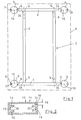
- FIG. 1 is the basic view of the frame (2) according to the invention shown in Connection with, for example, a slab of the substructure for a table (1), desk, furniture or the like can represent.
- the frame (2) has one H-shape, after which two longitudinal bars (4) on the front two cross bars (3) through a butt screw connection (9) are connected.
- the tubular profiles (5) have on them Outer surface along a surface line each a first groove (6) whose width corresponds to the width of the cross member (3) equivalent.
- the free spar end (24) is in this first Groove (6) guided and thus secured against rotation.
- the tubular profile (5) On the side opposite the first groove (6) the tubular profile (5) has a second groove (7) through a Cover profile (8) is covered.
- This second groove (7) is used on the one hand to accommodate the screw heads for the Screws (10) and on the other hand forms one Cable duct (25) (see FIG. 6).
- the longitudinal spar (4) or transverse spar (3) is one in Cross section of rectangular hollow profile (11) made of light metal, in particular from an extruded hollow profile (11) educated.
- On the inside of the narrow sides of the Hollow profile (11) are two in the distance mutually arranged webs (12) extending in the direction extend to the interior and one between them Form screw channel (13).
- This screw channel (13) takes the individual screw connection (9,10), whose Screw shanks have self-tapping properties.
- the Web outer surface (15) parallel to the outer surface (17) of the Hollow profile (11) should be.
- the outer surface of the bridge serves (15) as a support for the screw head (18) Screw connection (9). Accordingly, the profile wall a through hole (19), the size of the Screw head (18) corresponds. If the distance (16) between the outer surface of the web (15) and the Profile outer surface (17) of the height of the screw head (18) corresponds, then the screw (10) with your Screw head (18) flush with the outer surface (17) of the Hollow profile (11).
- a second groove (7) lies opposite this first groove (6), which forms a channel (25) which leads to the outside through a Cover profile (8) is completed.
- This cover profile (8) becomes snap-lock-like with the help of its webs (27) inserted into the groove (7).
- the webs are accordingly (27) of the cover profile (8) and the side walls (28) of the second groove (7) curved or set back, to bring about the snap lock connection.
- Figures 5 and 10 describe the connection of a Plate (38) with the legs (5), shown at the same time as the plate (38) using the below described fittings in one or more inclined positions can be adjusted.
- the leg shown in Figure 5 (5) is in this example with the back of the plate (38) and the leg (5) shown in Figure 10 with the Front of the plate (38) connected.
- leg becomes one z.
- B plastic cap (30) used the has a central through bore (31) therein to guide the pin (32) of a fitting (36).
- This Cap (30) has an outer disc (55) which has the same diameter as the tubular profile (5).
- the hub (33) of the cap (30) is, as in FIG. 4, already has been described, between the webs (22) and the Groove bottom (20) of the hollow profile (5) out.
- Two bar-like extensions extend from the hub (33) Lugs (34) to the outside, their circumference in the tubular profile (5) is led.
- the pin (32) guided in the hub (33) of the cap (30) has a series of bores (40) transverse to the longitudinal axis that have the same distance from each other.
- a radial in the bolt-like approach (34) Threaded hole for receiving a locking element (41), that in the example of Figure 6 as grub screws is trained.
- This locking element (41) has a protruding locking ball (42) on the front, the is rotatably guided in the locking element (41) and below the action of a spring (43).
- the locking ball (42) protrudes slightly over the locking element (41) on the front out and engages in a bore (40) of the pin (32) on. Positional centering is thereby brought about.
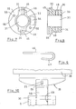
- pin hook (46) inserted penetrates the associated bore (40) of the pin (32) and merges into a hook part (47).
- This hook part (47) is dimensioned so that it is from the outside in another Bore (40) of the pin (32) can engage.
- the hook part (47) is slightly V-shaped.
- the Pen hook (46) consists of a resilient material, so that when inserting the hook part (47) into the hole (40) to overcome a pretension of the hook part (47) is. As a result, the pin hook (46) is automatically activated Loosened from the pin (32) prevented.
- the diameter of the hub (33) is to be dimensioned such that between the outer circumference of the Hub (33) and the groove bottom (26) created enough space to insert the screw head (18) for the To accommodate screw (10).
- the cap (30) is in Figures 7 and 8 as a single part shown again, whereby it can be seen that in the End plate of the cap (30) has a recess (54) is which to the channel (25) of the tubular profile (5) of the leg should be congruent. This is supposed to be the opportunity be created, cables also through the front Completion of the pipe profile (5) to be able to pass.
- Figure 10 shows the arrangement of the cap (30) at the upper end of the front tubular profile (5) of the leg, with a Spindle pin (50) of a fitting (35) in the bore the cap (30) engages as a threaded hole can be trained. You can therefore the fitting (35) in adjust the height compared to the tubular profile (5) and a Inclination of the plate (38) in the desired Fix inclination.
- This Fitting (36) has a flange plate (37) on which for example a plate (38), e.g. B. a table top or screwed the bottom of a piece of furniture.
- the Flange plate (37) is rotatable on the joint (39) Journals (32) stored. This will give you the opportunity created to adjust the plate (38) at an angle.
- the Arrangement with pin (51) and slot (52) on the fitting (35) of the front leg (5) is provided.
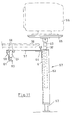
- Add-on unit for example in the form of a PC support (57).
- the plate (38) and a spar (3 or 4) are hinted at.
- the spar (3, 4) is supported a mounting plate (57) in the manner of a sliding guide (58) from the side acting on the spar (3,4) Has guide rollers (59).
- a locking screw (60) on one of the spar (3,4) encompassing bearing block (61) is guided.
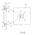
- FIG. 12 shows the mounting plate (57) in Embodiment designed triangular. Accordingly, it points two sliding guides (58) and a holder (62) for the Connection with one leg (63).
- This bracket (62) can contain, for example, an angle (64), the upright leg is dimensioned so that it fits into the groove (6) intervenes, as shown specifically in Fig. 4. This creates a torsionally rigid connection.
- a pin (32) is adjustable in height, which on upper end a plate (65) for receiving a PC (66) wearing.
- This design has the advantage that the PC (66) does not take up space on the worktop (38) of the frame-like frame (2).
- the leg (63) is supported with a foot (67) or a roller against the floor.
- the cap (30) axially parallel bores (56) to provide through which screws, not shown, for direct attachment of the disc (55) to the lower surface the plate (38) are guided.
- the cap so attached (30) after insertion into the tubular profile (5) of the Leg secured by radial screwing.
- the cap (30) can also be attached to the lower end of the leg (5) can be connected to, for example, uneven floors compensate.
- a continuous thread (49) (such as shown in Figure 10) and in it the threaded pin of a footplate is adjustable in height to screw.
Landscapes
- Furniture Connections (AREA)
- Mutual Connection Of Rods And Tubes (AREA)
- Laminated Bodies (AREA)
Description
- Figur 1:
- eine Draufsicht auf H-förmiges Gestell mit Längs- und Querholmen sowie Beinen,
- Figur 2:
- einen Querschnitt durch ein rechteckiges Hohlprofil zur Verwendung als Längs- oder/und Querholm,
- Figur 3:
- einen Querschnitt durch das Hohlprofil gemäß Figur 2 in Verbindung mit einer Stoßverschraubung zu einem anderen Hohlprofil,
- Figur 4:
- einen Querschnitt durch eine Stoßverbindung zwischen dem Hohlprofil eines Holmes und dem Rohrprofil eines Beines,
- Figur 5:
- einen Querschnitt durch den oberen Bereich eines hinteren Beines mit einem eingesetzten Beschlag zur Schrägstellung einer Tischplatte,
- Figur 6:
- einen Querschnitt durch das Bein längs der Linie VI-VI in Figur 5,
- Figuren 7 und 8:
- Stirnansicht und Querschnitt durch eine in das Rohrprofil des Beines einsetzbare Kappe,
- Figur 9:
- eine Ansicht eines Stifthakens,
- Figur 10:
- eine Seitenansicht auf einen in das obere Ende eines vorderen Beines einsetzbaren Beschlag zur Schrägstellung einer Tischplatte,
- Figur 11:
- Seitenansicht eines an das rahmenartige Gestell anschließbaren PC-Supports und
- Figur 12:
- eine Draufsicht auf den PC-Support gemäß Figur 11.
Das Bein (63) ist mit einem Fuß (67) oder einer Rolle gegenüber dem Boden abgestützt.
- 1
- Tisch, Pult oder dergleichen
- 2
- Gestell aus Leichtmetall
- 3
- Querholm
- 4
- Längsholm
- 5
- Bein, Rohrprofil
- 6
- erste Nut
- 7
- zweite Nut
- 8
- Abdeckprofil
- 9
- Verschraubung
- 10
- Verschraubung
- 11
- Hohlprofil aus Leichtmetall
- 12
- Steg
- 13
- Schraubkanal
- 14
- Zwischenraum
- 15
- Stegaußenfläche
- 16
- Abstand
- 17
- Profilaußenfläche
- 18
- Schraubenkopf
- 19
- Durchgangsbohrung
- 20
- Nutboden
- 21
- Durchgangsbohrung
- 22
- Führungssteg
- 23
- Kreisbogen
- 24
- freies Holmende
- 25
- Kanal
- 26
- Nutboden
- 27
- Steg
- 28
- Seitenwand
- 29
- Zapfen
- 30
- Kappe
- 31
- Bohrung
- 32
- Zapfen
- 33
- Nabe
- 34
- riegelartiger Ansatz
- 35
- Beschlag (Fußteil)
- 36
- Beschlag
- 37
- Flanschplatte
- 38
- Platte
- 39
- Gelenk
- 40
- Bohrung
- 41
- Arretierelement (Madenschraube)
- 42
- Arretierbügel
- 43
- Feder
- 44
- Außenfläche
- 45
- hohlkehlenförmige Rinne
- 46
- Stifthaken
- 47
- Hakenteil
- 48
- Gewindebohrung
- 49
- Gewindebohrung
- 50
- Spindelzapfen
- 51
- Stift
- 52
- Langloch
- 53
- Durchgangsbohrung
- 54
- Aussparung
- 55
- Scheibe
- 56
- Bohrung
- 57
- Befestigungsblech
- 58
- Gleitführung
- 59
- Führungsrolle
- 60
- Feststellschraube
- 61
- Lagerbock
- 62
- Halterung
- 63
- Bein
- 64
- Winkel
- 65
- Platte
- 66
- PC
- 67
- Fuß
Claims (20)
- Rahmenartiges Gestell (2) als Unterbau für Tische (1), Pulte, Möbel oder dergleichen, bestehend aus miteinander verschraubten metallischen Hohlprofilen (3, 4, 5), insbesondere Leichtmetall-Strangpreßprofilen, wobei Längs- und Querholme (4,3) des Gestells (2) einen H-förmigen Rahmen bilden, an dessen freien Holmenden (24) die Beine (5) des Gestells (2) befestigt sind, dadurch gekennzeichnet, daß die Längs- und Querholme (4,3) einen rechteckigen Querschnitt aufweisen, an dessen schmalen Seiten zwei Stege (12), die zwischen sich einen durchlaufenden Schraubkanal (13) bilden, nach innen ragen, und daß die Beine (5) des Gestells (2) aus einem Rohrprofil bestehen, an dessen Außenfläche eine längs einer Mantellinie sich erstreckende erste Nut (6) vorgesehen ist, in der die schmale Seite des freien Holmendes (24) geführt ist.
- Gestell nach Anspruch 1, dadurch gekennzeichnet, daß an die Stirnseiten von zwei zueinander parallelen Längsholmen (4) die kürzeren Querholme (3) unter Bildung einer T-förmigen Stoßverbindung angeschraubt sind und daß die Querholme (3) die freien Holmenden (24) aufweisen.
- Gestell nach Anspruch 1 oder 2, dadurch gekennzeichnet, daß die Außenflächen (15) der Stege (12) sich parallel zu den breiteren Außenflächen (17) der Holmprofile (3,4) erstrecken und als Stützfläche für quer zur Profillängsachse angeordnete, die Außenfläche (17) durchsetzende Schraubenköpfe (53) dienen.
- Gestell nach Anspruch 3, dadurch gekennzeichnet, daß der Abstand (16) der Stegaußenfläche (15) zur Profilaußenfläche (17) der Höhe eines Schraubenkopfes (53) entspricht, der eine entsprechende Durchgangsbohrung (19) in der Profilwand bündig ausfüllt.
- Gestell nach Anspruch 1 oder einem der folgenden, dadurch gekennzeichnet, daß das Rohrprofil (5) eine zweite, längs einer Mantellinie sich erstreckende, außenliegende Nut (7) aufweist, die der ersten Nut (6) für die Aufnahme des freien Holmendes (24) gegenüberliegt und durch ein U-förmiges Abdeckprofil (8) unter Belassung eines durchlaufenden Kanals (25) verschließbar ist.
- Gestell nach Anspruch 5, dadurch gekennzeichnet, daß im Boden der zweiten Nut (7) zwei Durchgangsbohrungen (21) für die Köpfe (53) von Schrauben (10) vorgesehen sind, welche sich an der Innenfläche des Bodens (26) der ersten Nut (6) abstützen und deren Gewindeschäfte selbstschneidend in die Schraubkanäle (13) der freien Holmenden (24) eingreifen.
- Gestell nach Anspruch 5 oder 6, dadurch gekennzeichnet, daß die Stege (27) des Abdeckprofils (8) schnappverschlußartig in Hinterschneidungen der Seitenwände (28) der zweiten Nut (7) eingreifen.
- Gestell nach einem der Ansprüche 5 bis 7, dadurch gekennzeichnet, daß der vom Abdeckprofil (8) umschlossene Kanal (25) für die Aufnahme von Kabeln bestimmt ist.
- Gestell nach Anspruch 1 oder einem der folgenden, dadurch gekennzeichnet, daß im Rohrprofil des Beins (5) radial sich erstreckende Stege (22) mit ihren Enden im Zusammenwirken mit dem Boden (20) der zweiten Nut (7) eine Führung für eine in das Bein (5) einschiebbare Nabe (33) bilden.
- Gestell nach Anspruch 9, dadurch gekennzeichnet, daß der Boden (20) der zweiten Nut (7) entsprechend der Krümmung (23) der Nabe (33) gewölbt ausgebildet ist.
- Gestell nach Anspruch 1 oder einem der folgenden, dadurch gekennzeichnet, daß in das einzelne Beinende (5) eine insbesondere aus Kunststoff bestehende Kappe (30) eingesetzt ist, die eine axiale durchgehende Bohrung (31) für die Aufnahme eines Zapfens (32) aufweist, wobei die Nabe (33) der Kappe (30) an den Stegen (22) und dem Boden (20) der zweiten Nut (7) des Beinprofils (5) geführt ist und mit riegelartigen Ansätzen (34) in den Raum zwischen den Stegen (22) und dem Boden (20) der zweiten Nut (7) ragt.
- Gestell nach Anspruch 11, dadurch gekennzeichnet, daß der Zapfen (32) Bestandteil eines Beschlages (35,36) ist, der als Fußteil (35) oder Flansch (36) zur Befestigung an einer Platte (38) bestimmt ist.
- Gestell nach Anspruch 12, dadurch gekennzeichnet, daß eine Flanschplatte (37) gelenkig (39) mit dem Zapfen (34) verbunden ist.
- Gestell nach Anspruch 12 oder 13, dadurch gekennzeichnet, daß im Zapfen (32) eine Reihe radialer Bohrungen (40) und in einem riegelartigen Ansatz (34) der Kunststoff kappe (30) ein radiales Arretierelement (41) angeordnet ist, das in eine der Bohrungen (40) eingreift.
- Gestell nach Anspruch 14, dadurch gekennzeichnet, daß das Arretierelement (41) als Madenschraube mit einer darin federnd geführten Arretierkugel (42) ausgebildet ist, die in die Bohrung (40) eingreift.
- Gestell nach Anspruch 11 oder einem der folgenden, dadurch gekennzeichnet, daß in der stirnseitigen Außenfläche (44) der Kappe (30) eine radial sich erstreckende hohlkehlenförmige Rinne (45) vorgesehen ist, in der ein U-förmiger Stifthaken (46) geführt ist, der eine der Bohrungen (40) durchsetzt und mit seinem gekrümmten Hakenteil (47) in eine andere Bohrung (40) sichernd eingreift.
- Gestell nach Anspruch 16, dadurch gekennzeichnet, daß der Hakenteil (47) federnde Eigenschaft hat und leicht V-förmig geformt ist.
- Gestell nach Anspruch 11 oder einem der folgenden, dadurch gekennzeichnet, daß die Kappe (30) eine durchgehende Gewindebohrung (49) aufweist, in der ein Spindelzapfen (50) eines als Fußteil ausgebildeten Beschlages (35) höhenverstellbar geführt ist.
- Gestell nach Anspruch 1 oder einem der folgenden, dadurch gekennzeichnet, daß an einem Längs- oder Querholm (4,3) des rahmenartigen Gestells (2) eine Gleitführung (58). längsverschieblich und feststellbar angeordnet ist, die über ein Befestigungsblech (57) oder dergleichen mit einem außerhalb des Tisches (1) vorgesehenen Bein (63) verbunden ist, das sich am Boden abstützt und beispielsweise einen PC trägt.
- Gestell nach Anspruch 19, dadurch gekennzeichnet, daß das Befestigungsblech (57) über einen Winkel (64) nit dem Bein (63) verbunden ist, wobei der aufrechte Schenkel des Winkels (64) in eine außenliegende Längsnut (6) des Beines (63) drehstarr eingreift.
Applications Claiming Priority (2)
| Application Number | Priority Date | Filing Date | Title |
|---|---|---|---|
| DE29609291U DE29609291U1 (de) | 1996-05-24 | 1996-05-24 | Rahmenartiges Gestell als Unterbau für Tische u.dgl. |
| DE29609291U | 1996-05-24 |
Publications (3)
| Publication Number | Publication Date |
|---|---|
| EP0808588A2 EP0808588A2 (de) | 1997-11-26 |
| EP0808588A3 EP0808588A3 (de) | 1998-10-14 |
| EP0808588B1 true EP0808588B1 (de) | 2002-04-03 |
Family
ID=8024350
Family Applications (1)
| Application Number | Title | Priority Date | Filing Date |
|---|---|---|---|
| EP97107980A Expired - Lifetime EP0808588B1 (de) | 1996-05-24 | 1997-05-16 | Rahmenartiges Gestell als Unterbau für Tische und dergleichen |
Country Status (3)
| Country | Link |
|---|---|
| EP (1) | EP0808588B1 (de) |
| AT (1) | ATE215329T1 (de) |
| DE (2) | DE29609291U1 (de) |
Families Citing this family (2)
| Publication number | Priority date | Publication date | Assignee | Title |
|---|---|---|---|---|
| DE29809994U1 (de) * | 1998-06-04 | 1999-10-07 | Oelschläger Metalltechnik GmbH, 27318 Hoya | Modular aufgebautes Tischgestell |
| JP7110523B2 (ja) * | 2017-10-23 | 2022-08-02 | コクヨ株式会社 | 天板付き家具 |
Family Cites Families (13)
| Publication number | Priority date | Publication date | Assignee | Title |
|---|---|---|---|---|
| DE1747921U (de) * | 1957-04-23 | 1957-07-04 | Konrad Hall O H G Tischfabrik | Hoehenverstellbarer tisch. |
| DE1862186U (de) * | 1962-09-18 | 1962-11-15 | Haslocher Ausziehtisch Und Moe | Tisch oder stuhl mit zerlegbarem aus miteinander verschraubbaren rund- oder vierkantrohren bestehendem untergestell. |
| FR2358127A1 (fr) * | 1976-07-12 | 1978-02-10 | Marcadet Mobilier Ateliers | Structure porteuse pour assemblage d'elements modulaires constitutifs de bureaux, de configurations diverses |
| DE8137388U1 (de) * | 1981-12-22 | 1982-04-22 | Waiko Möbelwerke GmbH & Co KG, 7071 Durlangen | Hohlprofil |
| DE3232766C1 (de) * | 1982-09-03 | 1984-03-22 | 3K-Büromöbel GmbH, 6143 Lorsch | Aus Profilteilen bestehendes Gestell |
| DE8705611U1 (de) * | 1987-04-15 | 1987-06-25 | ceka - Büromöbel Werke C. Krause und Sohn GmbH u. Co KG, 6320 Alsfeld | Rahmen für Tisch-, Geräte- od. dgl. Arbeitsplatten, insbesondere für Büroarbeitsplätze |
| DE8811309U1 (de) * | 1988-09-07 | 1988-10-27 | Faulenbach, Neithard, 5653 Leichlingen | Bauteil für Rahmen- und/oder Tragkonstruktionen |
| FR2665512B1 (fr) * | 1990-07-11 | 1992-12-24 | Technal Sa | Dispositif pour la liaison de trois profiles metalliques. |
| DE4142273C2 (de) * | 1991-12-20 | 1996-04-18 | Bosch Gmbh Robert | Vorrichtung zum lösbaren Verbinden von zwei in einer Ebene senkrecht aufeinanderstehenden Strebenprofilen |
| DE9203100U1 (de) * | 1992-03-09 | 1993-07-08 | Böwe Systec AG, 8900 Augsburg | Grundgestell für Maschinen u.dgl. |
| DE4220178A1 (de) * | 1992-06-19 | 1993-12-23 | Ernst Moeckl | Tragstrukturelement für Traggestelle von Tischmöbeln und dergleichen Möbelstücken sowie Verfahren zur Herstellung eines solchen Tragstrukturelements |
| DE4323488A1 (de) * | 1993-07-14 | 1995-01-19 | Heinz Zerfas | Montage-Elemente |
| DE9319206U1 (de) * | 1993-12-16 | 1994-11-10 | Julius & August Erbslöh GmbH & Co, 42553 Velbert | Profil für die Bildung von Gerüstkonstruktionen |
-
1996
- 1996-05-24 DE DE29609291U patent/DE29609291U1/de not_active Expired - Lifetime
-
1997
- 1997-05-16 DE DE59706825T patent/DE59706825D1/de not_active Expired - Fee Related
- 1997-05-16 AT AT97107980T patent/ATE215329T1/de not_active IP Right Cessation
- 1997-05-16 EP EP97107980A patent/EP0808588B1/de not_active Expired - Lifetime
Also Published As
| Publication number | Publication date |
|---|---|
| EP0808588A2 (de) | 1997-11-26 |
| ATE215329T1 (de) | 2002-04-15 |
| DE59706825D1 (de) | 2002-05-08 |
| DE29609291U1 (de) | 1997-06-26 |
| EP0808588A3 (de) | 1998-10-14 |
Similar Documents
| Publication | Publication Date | Title |
|---|---|---|
| EP0790792B1 (de) | Tisch | |
| EP0940105B1 (de) | Ausziehvorrichtung für Hochschränke | |
| EP0491762B1 (de) | Tisch | |
| DE3420648A1 (de) | Buerotisch, insbesondere fuer computer-peripheriegeraete | |
| DE2514357B2 (de) | Beschlag zum verschwenkbaren Verbinden einer Möbelplatte mit einem feststehenden Möbelteil | |
| DE4337939C2 (de) | Fahrzeugsitz, insbesondere Fluggastsitz | |
| EP2159345B1 (de) | Halterung für Verkleidungselemente | |
| DE29613666U1 (de) | Führungsgestell | |
| DE3629368A1 (de) | Profilstab | |
| EP0913139B1 (de) | Modulares OP-Tischsystem | |
| DE69301708T2 (de) | Gelenkiges Rahmenelement für Hausrat-Baukastensystem und Scharnier für die gelenkige Verbindung zweier Rahmenelemente | |
| DE4332437C2 (de) | Tisch und Tischsystem | |
| DE29605407U1 (de) | Tisch, insbesondere für Büroarbeitsplätze | |
| EP0808588A2 (de) | Rahmenartiges Gestell als Unterbau für Tische und dergleichen | |
| DE4220178A1 (de) | Tragstrukturelement für Traggestelle von Tischmöbeln und dergleichen Möbelstücken sowie Verfahren zur Herstellung eines solchen Tragstrukturelements | |
| EP0322403B1 (de) | Schrank | |
| DE3540015C2 (de) | ||
| DE60000313T2 (de) | Befestigungssystem an einer Säule für ein Trägerelement | |
| DE3109893C2 (de) | ||
| EP1169943B1 (de) | Ausziehrahmen für Hochschränke | |
| DE19921324A1 (de) | Ausziehrahmen für Hochschränke | |
| DE9319660U1 (de) | Trennwandsystem | |
| DE3049841T1 (de) | Process for manufacturing furniture assembled by tubular sections furniture according to said process | |
| DE3535423C2 (de) | Beschlag für eine in der Höhe und in der Neigung einstellbare Platte eines Arbeitstisches oder dergleichen | |
| DE4232871A1 (de) | Profilstütze für Raumteilerkonstruktionen und dergleichen |
Legal Events
| Date | Code | Title | Description |
|---|---|---|---|
| PUAI | Public reference made under article 153(3) epc to a published international application that has entered the european phase |
Free format text: ORIGINAL CODE: 0009012 |
|
| AK | Designated contracting states |
Kind code of ref document: A2 Designated state(s): AT BE CH DE DK ES FR GB IT LI LU NL SE |
|
| PUAL | Search report despatched |
Free format text: ORIGINAL CODE: 0009013 |
|
| AK | Designated contracting states |
Kind code of ref document: A3 Designated state(s): AT BE CH DE DK ES FR GB IT LI LU NL SE |
|
| RAP1 | Party data changed (applicant data changed or rights of an application transferred) |
Owner name: ERICH KELLER AG |
|
| 17P | Request for examination filed |
Effective date: 19990112 |
|
| 17Q | First examination report despatched |
Effective date: 20001205 |
|
| GRAG | Despatch of communication of intention to grant |
Free format text: ORIGINAL CODE: EPIDOS AGRA |
|
| GRAG | Despatch of communication of intention to grant |
Free format text: ORIGINAL CODE: EPIDOS AGRA |
|
| GRAH | Despatch of communication of intention to grant a patent |
Free format text: ORIGINAL CODE: EPIDOS IGRA |
|
| REG | Reference to a national code |
Ref country code: GB Ref legal event code: IF02 |
|
| GRAH | Despatch of communication of intention to grant a patent |
Free format text: ORIGINAL CODE: EPIDOS IGRA |
|
| GRAA | (expected) grant |
Free format text: ORIGINAL CODE: 0009210 |
|
| AK | Designated contracting states |
Kind code of ref document: B1 Designated state(s): AT BE CH DE DK ES FR GB IT LI LU NL SE |
|
| PG25 | Lapsed in a contracting state [announced via postgrant information from national office to epo] |
Ref country code: NL Free format text: LAPSE BECAUSE OF FAILURE TO SUBMIT A TRANSLATION OF THE DESCRIPTION OR TO PAY THE FEE WITHIN THE PRESCRIBED TIME-LIMIT Effective date: 20020403 Ref country code: IT Free format text: LAPSE BECAUSE OF FAILURE TO SUBMIT A TRANSLATION OF THE DESCRIPTION OR TO PAY THE FEE WITHIN THE PRE;WARNING: LAPSES OF ITALIAN PATENTS WITH EFFECTIVE DATE BEFORE 2007 MAY HAVE OCCURRED AT ANY TIME BEFORE 2007. THE CORRECT EFFECTIVE DATE MAY BE DIFFERENT FROM THE ONE RECORDED.SCRIBED TIME-LIMIT Effective date: 20020403 Ref country code: GB Free format text: LAPSE BECAUSE OF FAILURE TO SUBMIT A TRANSLATION OF THE DESCRIPTION OR TO PAY THE FEE WITHIN THE PRESCRIBED TIME-LIMIT Effective date: 20020403 Ref country code: FR Free format text: LAPSE BECAUSE OF FAILURE TO SUBMIT A TRANSLATION OF THE DESCRIPTION OR TO PAY THE FEE WITHIN THE PRESCRIBED TIME-LIMIT Effective date: 20020403 |
|
| REF | Corresponds to: |
Ref document number: 215329 Country of ref document: AT Date of ref document: 20020415 Kind code of ref document: T |
|
| REG | Reference to a national code |
Ref country code: CH Ref legal event code: NV Representative=s name: FREI PATENTANWALTSBUERO Ref country code: CH Ref legal event code: EP |
|
| REF | Corresponds to: |
Ref document number: 59706825 Country of ref document: DE Date of ref document: 20020508 |
|
| PG25 | Lapsed in a contracting state [announced via postgrant information from national office to epo] |
Ref country code: LU Free format text: LAPSE BECAUSE OF NON-PAYMENT OF DUE FEES Effective date: 20020516 |
|
| PG25 | Lapsed in a contracting state [announced via postgrant information from national office to epo] |
Ref country code: BE Free format text: LAPSE BECAUSE OF NON-PAYMENT OF DUE FEES Effective date: 20020531 |
|
| PG25 | Lapsed in a contracting state [announced via postgrant information from national office to epo] |
Ref country code: SE Free format text: LAPSE BECAUSE OF FAILURE TO SUBMIT A TRANSLATION OF THE DESCRIPTION OR TO PAY THE FEE WITHIN THE PRESCRIBED TIME-LIMIT Effective date: 20020703 Ref country code: DK Free format text: LAPSE BECAUSE OF FAILURE TO SUBMIT A TRANSLATION OF THE DESCRIPTION OR TO PAY THE FEE WITHIN THE PRESCRIBED TIME-LIMIT Effective date: 20020703 |
|
| NLV1 | Nl: lapsed or annulled due to failure to fulfill the requirements of art. 29p and 29m of the patents act | ||
| GBV | Gb: ep patent (uk) treated as always having been void in accordance with gb section 77(7)/1977 [no translation filed] |
Effective date: 20020403 |
|
| PG25 | Lapsed in a contracting state [announced via postgrant information from national office to epo] |
Ref country code: ES Free format text: LAPSE BECAUSE OF FAILURE TO SUBMIT A TRANSLATION OF THE DESCRIPTION OR TO PAY THE FEE WITHIN THE PRESCRIBED TIME-LIMIT Effective date: 20021030 |
|
| EN | Fr: translation not filed | ||
| PLBE | No opposition filed within time limit |
Free format text: ORIGINAL CODE: 0009261 |
|
| STAA | Information on the status of an ep patent application or granted ep patent |
Free format text: STATUS: NO OPPOSITION FILED WITHIN TIME LIMIT |
|
| 26N | No opposition filed |
Effective date: 20030106 |
|
| PGFP | Annual fee paid to national office [announced via postgrant information from national office to epo] |
Ref country code: CH Payment date: 20030422 Year of fee payment: 7 |
|
| PGFP | Annual fee paid to national office [announced via postgrant information from national office to epo] |
Ref country code: AT Payment date: 20030506 Year of fee payment: 7 |
|
| PGFP | Annual fee paid to national office [announced via postgrant information from national office to epo] |
Ref country code: DE Payment date: 20030730 Year of fee payment: 7 |
|
| PG25 | Lapsed in a contracting state [announced via postgrant information from national office to epo] |
Ref country code: AT Free format text: LAPSE BECAUSE OF NON-PAYMENT OF DUE FEES Effective date: 20040516 |
|
| PG25 | Lapsed in a contracting state [announced via postgrant information from national office to epo] |
Ref country code: LI Free format text: LAPSE BECAUSE OF NON-PAYMENT OF DUE FEES Effective date: 20040531 Ref country code: CH Free format text: LAPSE BECAUSE OF NON-PAYMENT OF DUE FEES Effective date: 20040531 |
|
| PG25 | Lapsed in a contracting state [announced via postgrant information from national office to epo] |
Ref country code: DE Free format text: LAPSE BECAUSE OF NON-PAYMENT OF DUE FEES Effective date: 20041201 |
|
| REG | Reference to a national code |
Ref country code: CH Ref legal event code: PL |