EP0807899A2 - Procédé et dispositif pour lire un code sur un porteur de code - Google Patents
Procédé et dispositif pour lire un code sur un porteur de code Download PDFInfo
- Publication number
- EP0807899A2 EP0807899A2 EP97107820A EP97107820A EP0807899A2 EP 0807899 A2 EP0807899 A2 EP 0807899A2 EP 97107820 A EP97107820 A EP 97107820A EP 97107820 A EP97107820 A EP 97107820A EP 0807899 A2 EP0807899 A2 EP 0807899A2
- Authority
- EP
- European Patent Office
- Prior art keywords
- light
- code
- reflecting surface
- fields
- scanning area
- Prior art date
- Legal status (The legal status is an assumption and is not a legal conclusion. Google has not performed a legal analysis and makes no representation as to the accuracy of the status listed.)
- Withdrawn
Links
Images

Classifications
-
- G—PHYSICS
- G06—COMPUTING OR CALCULATING; COUNTING
- G06K—GRAPHICAL DATA READING; PRESENTATION OF DATA; RECORD CARRIERS; HANDLING RECORD CARRIERS
- G06K7/00—Methods or arrangements for sensing record carriers, e.g. for reading patterns
- G06K7/10—Methods or arrangements for sensing record carriers, e.g. for reading patterns by electromagnetic radiation, e.g. optical sensing; by corpuscular radiation
- G06K7/10544—Methods or arrangements for sensing record carriers, e.g. for reading patterns by electromagnetic radiation, e.g. optical sensing; by corpuscular radiation by scanning of the records by radiation in the optical part of the electromagnetic spectrum
- G06K7/10712—Fixed beam scanning
- G06K7/10762—Relative movement
-
- G—PHYSICS
- G06—COMPUTING OR CALCULATING; COUNTING
- G06K—GRAPHICAL DATA READING; PRESENTATION OF DATA; RECORD CARRIERS; HANDLING RECORD CARRIERS
- G06K7/00—Methods or arrangements for sensing record carriers, e.g. for reading patterns
- G06K7/10—Methods or arrangements for sensing record carriers, e.g. for reading patterns by electromagnetic radiation, e.g. optical sensing; by corpuscular radiation
- G06K7/10544—Methods or arrangements for sensing record carriers, e.g. for reading patterns by electromagnetic radiation, e.g. optical sensing; by corpuscular radiation by scanning of the records by radiation in the optical part of the electromagnetic spectrum
- G06K7/10554—Moving beam scanning
Definitions
- the invention relates to a method and a device for reading a code provided on a code carrier and consisting of intact and dark fields, in particular a bar code, in which the code is scanned with a light beam generated by a light transmitter, such as in particular a laser beam, and is reflected back to a light receiving arrangement Light is evaluated.
- the known devices of the type mentioned include the so-called bar code reader, which is used for reading codes formed from light and dark bars or lines.
- the dark fields can also be formed by holes, for example, provided that it is ensured that there are no reflective materials behind the holes. It is essential that the incident light is more strongly absorbed by the dark fields and more strongly reflected by the bright fields, which makes it possible to distinguish between the different fields.
- the problem can arise that only a small part of the light striking a respective bright field reaches the light receiving arrangement again if the surface condition of the code carrier is specular or highly reflective. If, for example, the dark code fields are applied to a bare, polished metal surface and the light code fields are formed by this metal surface, then due to the lack of scatter reflectivity, even with a scanning beam hitting a bright code field, very little light can reach the light receiving arrangement reached. It is therefore no longer possible to differentiate between the light-absorbing dark fields on the one hand and the light fields on the other. Methods are known in which different printing inks are used and the background is inversely colored in the reverse manner. However, this requires additional effort.
- the aim of the invention is to provide an improved method and an improved device of the type mentioned at the outset, with which code detection which is as error-free as possible is always ensured in a simple and inexpensive manner.
- the object is achieved in the method according to the invention in that at least some of the light which is differently reflected by the scanned code fields and is no longer reaching the light receiving arrangement is returned to the scanning area by at least one reflecting surface, this light being reflected differently by the code fields and then again the contrast detected by the light receiving arrangement is significantly increased as a function of the code fields.
- the device according to the invention is specified in claim 6.
- the reflecting surface is preferably a diffusely scattering reflecting or retroreflective surface. This ensures that even with a strongly reflecting code carrier surface or with strongly reflecting bright fields, sufficient light is still incident on the light receiving arrangement as soon as the scanning beam is directed onto a respective bright field.
- the light output can be further increased by arranging the additional reflecting surface as close as possible to the scanning area.
- the reflecting surface is advantageously arranged in such a way that, if mirror reflection is assumed in the scanning area, the light beam reflected from the scanning area at the corresponding exit angle strikes the reflecting surface.
- a diffuse in particular becomes preferred scattering reflective or retroreflective surface used.
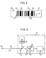
- FIG. 1 shows in a simplified schematic manner a device 10 for reading a code 14 provided on a code carrier 12 (see also FIG. 2).
- the device 10 comprises a transceiver part 16 with a light transmitter 18 and a light receiving arrangement 20 and an evaluation electronics 22 downstream of the light receiving arrangement 20 (see FIG. 3).
- a deflection unit such as a mirror wheel can also be integrated in the transceiver part 16 in order to effect a scanning movement of the light beam in question via the code carrier.
- the light transmitter 18 of the transmitting and receiving unit 16 delivers a light beam, in the present case a laser beam 24, through which a light spot 26 is generated on the code carrier 12, with which the code 14 is scanned in the direction of the arrow F.
- the code 14 in the present case is a bar or bar code, which is provided on a surface 28 of the code carrier 12.
- This code 14 comprises a plurality of dark, bar-like fields 30 applied, for example printed, to the surface 28 of the code carrier 12 concerned, as well as bright bar-like fields 32, which are formed directly by the surface 28 of the code carrier 18.
- the light spot 26 is guided, for example, in the direction designated F (see FIGS. 1 and 2) across the bar-like fields 30, 32 of the code 14.
- the bright fields 32 reflect light to the light receiving arrangement 20, where it is focused onto a photodiode 36 via a lens 34.
- At least one, preferably diffusely scattering, reflecting or retroreflective surface 38 is provided, by means of which at least some of the light reflected by the scanned code fields 30, 32 and not incident on the light receiving arrangement 20 is reflected back into the scanning area having the code 14 thereby increasing the proportion of light detected by the light receiving arrangement 20.
- This surface 38 which is scatteringly reflecting in the present case, is arranged close to the scanning area in which the scanning spot is located 26 mapped on the code 14, ie the code is scanned.
- the scattering reflecting surface 38 can be a white surface, for example, such as a surface formed by white paper or the like.
- a retroreflective surface can also be used.
- retroreflective surfaces are e.g. easy to manufacture with reflective foils. A function similar to that of white paper could be achieved with such a retroreflective surface, even with a greater distance of the surface from the code carrier.
- Such a retroreflective surface would therefore be particularly useful in the case that the depth of field, i.e. the range of the distance of the optical head to the code level can vary in the application.
- the scanning laser beam 24 emanating from the transmitting / receiving part 16 is directed onto the scanning area at a certain angle of incidence ⁇ .
- the scattering reflecting surface 38 is arranged such that a light beam 40 reflected at a corresponding exit angle ⁇ from the scanning range, in particular a respective bright field 32, occurs on the scattering reflecting surface 38 when mirror reflection is assumed in the scanning region.
- the incident light is at least partially scattered back to the scanning area, where it in particular also strikes at least one bright field 32.
- a corresponding proportion of light also reaches the light receiving arrangement 20 again by specular reflection, as a result of which the overall proportion of light detected by the light receiving arrangement 20 is increased.
- the transceiver part 16 comprises a beam splitter 42 or a closely-spaced pupil division (not shown), through which the laser beam 24 originating from the light transmitter 18 is deflected towards the code carrier to generate the light spot 26 scanning the code, and which deflects the reception beam 44 transmits so that it meets the light receiving arrangement 20.
- the transmit and receive beams 24 and 44 run essentially parallel to one another.
- the light receiving arrangement 20 still receives light from the bright fields 32 even if these should be formed by a reflective surface without scattering power.
- the lack of scatter reflectivity is compensated for by the scattering reflecting surface 38, through which light that is otherwise not detected by the light receiving arrangement 20 is reflected back into the scanning area, from where it at least partially reaches the light receiving arrangement 20.
- the device according to the invention thus ensures error-free reading of the code even if it should be provided on a bare, polished metal surface, ie the bright fields are formed by such a mirror surface.
Landscapes
- Physics & Mathematics (AREA)
- Electromagnetism (AREA)
- Engineering & Computer Science (AREA)
- Health & Medical Sciences (AREA)
- General Health & Medical Sciences (AREA)
- Toxicology (AREA)
- Artificial Intelligence (AREA)
- Computer Vision & Pattern Recognition (AREA)
- General Physics & Mathematics (AREA)
- Theoretical Computer Science (AREA)
- Mechanical Optical Scanning Systems (AREA)
- Character Input (AREA)
Applications Claiming Priority (2)
| Application Number | Priority Date | Filing Date | Title |
|---|---|---|---|
| DE19619479 | 1996-05-14 | ||
| DE19619479A DE19619479A1 (de) | 1996-05-14 | 1996-05-14 | Verfahren und Vorrichtung zum Lesen eines auf einem Codeträger vorgesehenen Codes |
Publications (2)
| Publication Number | Publication Date |
|---|---|
| EP0807899A2 true EP0807899A2 (fr) | 1997-11-19 |
| EP0807899A3 EP0807899A3 (fr) | 2000-02-23 |
Family
ID=7794324
Family Applications (1)
| Application Number | Title | Priority Date | Filing Date |
|---|---|---|---|
| EP97107820A Withdrawn EP0807899A3 (fr) | 1996-05-14 | 1997-05-13 | Procédé et dispositif pour lire un code sur un porteur de code |
Country Status (3)
| Country | Link |
|---|---|
| US (1) | US5929424A (fr) |
| EP (1) | EP0807899A3 (fr) |
| DE (1) | DE19619479A1 (fr) |
Families Citing this family (2)
| Publication number | Priority date | Publication date | Assignee | Title |
|---|---|---|---|---|
| US6661521B1 (en) * | 1998-09-11 | 2003-12-09 | Robotic Vision Systems, Inc. | Diffuse surface illumination apparatus and methods |
| US6611318B2 (en) | 2001-03-23 | 2003-08-26 | Automatic Timing & Controls, Inc. | Adjustable mirror for collimated beam laser sensor |
Family Cites Families (12)
| Publication number | Priority date | Publication date | Assignee | Title |
|---|---|---|---|---|
| US4201910A (en) * | 1978-03-27 | 1980-05-06 | Innovation Industries, Inc. | Photosensor assembly |
| US5545889A (en) * | 1985-02-28 | 1996-08-13 | Swartz; Jerome | Portable laser diode scanning head |
| US4766297A (en) * | 1987-01-08 | 1988-08-23 | Recognition Equipment Incorporated | Dual mode stationary and portable scanning system |
| US4960984A (en) * | 1988-02-04 | 1990-10-02 | Westinghouse Electric Corp. | Method and apparatus for reading lased bar codes on shiny-finished fuel rod cladding tubes |
| JPH0786899B2 (ja) * | 1988-04-28 | 1995-09-20 | 日本車輌製造株式会社 | バーコードの読取り方法 |
| US5594228A (en) * | 1988-08-25 | 1997-01-14 | Symbol Technologies, Inc. | Self-checkout, point-of-transaction system including deactivatable electro-optically coded surveillance tags |
| US5216232A (en) * | 1990-09-10 | 1993-06-01 | Metrologic Instruments, Inc. | Projection laser scanner producing a narrow scan volume |
| DE69232291T2 (de) * | 1991-10-29 | 2002-10-31 | Denso Corp., Kariya | Informations-lesegerät |
| JP3483217B2 (ja) * | 1994-02-08 | 2004-01-06 | チノン株式会社 | 画像読取装置 |
| JP3183767B2 (ja) * | 1994-02-21 | 2001-07-09 | 富士通株式会社 | レーザビーム走査装置 |
| NL9401302A (nl) * | 1994-08-11 | 1996-03-01 | Scantech Bv | Barcode scanner. |
| US5610385A (en) * | 1995-02-23 | 1997-03-11 | Ncr Corporation | Optical bar code scanner which produces substantially perpendicular scan lines |
-
1996
- 1996-05-14 DE DE19619479A patent/DE19619479A1/de not_active Withdrawn
-
1997
- 1997-05-13 EP EP97107820A patent/EP0807899A3/fr not_active Withdrawn
- 1997-05-13 US US08/855,177 patent/US5929424A/en not_active Expired - Fee Related
Also Published As
| Publication number | Publication date |
|---|---|
| US5929424A (en) | 1999-07-27 |
| EP0807899A3 (fr) | 2000-02-23 |
| DE19619479A1 (de) | 1997-11-20 |
Similar Documents
| Publication | Publication Date | Title |
|---|---|---|
| EP0354362B1 (fr) | Procédé de marquage et de lecture de codes lisibles optiquement, et bouteilles pourvues de telles marques | |
| DE69304348T2 (de) | Münzdetektor | |
| DE2131467C3 (de) | Lichtablenkvorriehtung zur Parallelverschiebung eines Lichtstrahls | |
| DE10341548A1 (de) | Optoelektronische Erfassungseinrichtung | |
| DE69124052T2 (de) | Laserstrahlstreifencodeleser | |
| DE602004005083T2 (de) | Eine Banknotendetektionseinheit für ein Banknotenerkennungsgerät | |
| EP1287496A1 (fr) | Appareil de verification de documents | |
| EP1207491B1 (fr) | Dispositif optoélectronique | |
| DE3750600T2 (de) | Kodierungsleser. | |
| EP0516927A2 (fr) | Système de code à bâtonnets | |
| EP0807899A2 (fr) | Procédé et dispositif pour lire un code sur un porteur de code | |
| EP3070496A1 (fr) | Dispositif de balayage a polygone et procede de detection d'objets | |
| EP1498747B1 (fr) | Appareil optoélectronique | |
| DE69732565T2 (de) | Vorrichtung und Verfahren zum Lesen eines optischen Codes | |
| DE19700281A1 (de) | Optischer Codeleser mit einer optischen Abtastvorrichtung | |
| CH663285A5 (de) | Optische abtastvorrichtung. | |
| DE69930984T2 (de) | Optische Vorrichtung zur Abtastung und Deckodierung eines Strichckodes | |
| EP0967458B2 (fr) | Capteur opto-électronique | |
| EP0988232A1 (fr) | Capteur pour etiquettes | |
| DE20006317U1 (de) | Vorrichtung zur Erkennung eines Gegenstands | |
| DE2163949C3 (de) | Lesevorrichtung für optisch erkennbare Zeichen | |
| DE19605505C2 (de) | Optische Abtastanordnung | |
| DE2552331C3 (de) | Abtastvorrichtung | |
| DE10101985A1 (de) | Optoelektronische Vorrichtung | |
| DE102004053293A1 (de) | Abtastvorrichtung für Barcodes |
Legal Events
| Date | Code | Title | Description |
|---|---|---|---|
| PUAI | Public reference made under article 153(3) epc to a published international application that has entered the european phase |
Free format text: ORIGINAL CODE: 0009012 |
|
| AK | Designated contracting states |
Kind code of ref document: A2 Designated state(s): DE FR GB |
|
| PUAL | Search report despatched |
Free format text: ORIGINAL CODE: 0009013 |
|
| AK | Designated contracting states |
Kind code of ref document: A3 Designated state(s): DE FR GB |
|
| STAA | Information on the status of an ep patent application or granted ep patent |
Free format text: STATUS: THE APPLICATION IS DEEMED TO BE WITHDRAWN |
|
| 18D | Application deemed to be withdrawn |
Effective date: 20000824 |