EP0807899A2 - Method and apparatus for reading a code on a code carrying means - Google Patents
Method and apparatus for reading a code on a code carrying means Download PDFInfo
- Publication number
- EP0807899A2 EP0807899A2 EP97107820A EP97107820A EP0807899A2 EP 0807899 A2 EP0807899 A2 EP 0807899A2 EP 97107820 A EP97107820 A EP 97107820A EP 97107820 A EP97107820 A EP 97107820A EP 0807899 A2 EP0807899 A2 EP 0807899A2
- Authority
- EP
- European Patent Office
- Prior art keywords
- light
- code
- reflecting surface
- fields
- scanning area
- Prior art date
- Legal status (The legal status is an assumption and is not a legal conclusion. Google has not performed a legal analysis and makes no representation as to the accuracy of the status listed.)
- Withdrawn
Links
Images

Classifications
-
- G—PHYSICS
- G06—COMPUTING OR CALCULATING; COUNTING
- G06K—GRAPHICAL DATA READING; PRESENTATION OF DATA; RECORD CARRIERS; HANDLING RECORD CARRIERS
- G06K7/00—Methods or arrangements for sensing record carriers, e.g. for reading patterns
- G06K7/10—Methods or arrangements for sensing record carriers, e.g. for reading patterns by electromagnetic radiation, e.g. optical sensing; by corpuscular radiation
- G06K7/10544—Methods or arrangements for sensing record carriers, e.g. for reading patterns by electromagnetic radiation, e.g. optical sensing; by corpuscular radiation by scanning of the records by radiation in the optical part of the electromagnetic spectrum
- G06K7/10712—Fixed beam scanning
- G06K7/10762—Relative movement
-
- G—PHYSICS
- G06—COMPUTING OR CALCULATING; COUNTING
- G06K—GRAPHICAL DATA READING; PRESENTATION OF DATA; RECORD CARRIERS; HANDLING RECORD CARRIERS
- G06K7/00—Methods or arrangements for sensing record carriers, e.g. for reading patterns
- G06K7/10—Methods or arrangements for sensing record carriers, e.g. for reading patterns by electromagnetic radiation, e.g. optical sensing; by corpuscular radiation
- G06K7/10544—Methods or arrangements for sensing record carriers, e.g. for reading patterns by electromagnetic radiation, e.g. optical sensing; by corpuscular radiation by scanning of the records by radiation in the optical part of the electromagnetic spectrum
- G06K7/10554—Moving beam scanning
Definitions
- the invention relates to a method and a device for reading a code provided on a code carrier and consisting of intact and dark fields, in particular a bar code, in which the code is scanned with a light beam generated by a light transmitter, such as in particular a laser beam, and is reflected back to a light receiving arrangement Light is evaluated.
- the known devices of the type mentioned include the so-called bar code reader, which is used for reading codes formed from light and dark bars or lines.
- the dark fields can also be formed by holes, for example, provided that it is ensured that there are no reflective materials behind the holes. It is essential that the incident light is more strongly absorbed by the dark fields and more strongly reflected by the bright fields, which makes it possible to distinguish between the different fields.
- the problem can arise that only a small part of the light striking a respective bright field reaches the light receiving arrangement again if the surface condition of the code carrier is specular or highly reflective. If, for example, the dark code fields are applied to a bare, polished metal surface and the light code fields are formed by this metal surface, then due to the lack of scatter reflectivity, even with a scanning beam hitting a bright code field, very little light can reach the light receiving arrangement reached. It is therefore no longer possible to differentiate between the light-absorbing dark fields on the one hand and the light fields on the other. Methods are known in which different printing inks are used and the background is inversely colored in the reverse manner. However, this requires additional effort.
- the aim of the invention is to provide an improved method and an improved device of the type mentioned at the outset, with which code detection which is as error-free as possible is always ensured in a simple and inexpensive manner.
- the object is achieved in the method according to the invention in that at least some of the light which is differently reflected by the scanned code fields and is no longer reaching the light receiving arrangement is returned to the scanning area by at least one reflecting surface, this light being reflected differently by the code fields and then again the contrast detected by the light receiving arrangement is significantly increased as a function of the code fields.
- the device according to the invention is specified in claim 6.
- the reflecting surface is preferably a diffusely scattering reflecting or retroreflective surface. This ensures that even with a strongly reflecting code carrier surface or with strongly reflecting bright fields, sufficient light is still incident on the light receiving arrangement as soon as the scanning beam is directed onto a respective bright field.
- the light output can be further increased by arranging the additional reflecting surface as close as possible to the scanning area.
- the reflecting surface is advantageously arranged in such a way that, if mirror reflection is assumed in the scanning area, the light beam reflected from the scanning area at the corresponding exit angle strikes the reflecting surface.
- a diffuse in particular becomes preferred scattering reflective or retroreflective surface used.
- FIG. 1 shows in a simplified schematic manner a device 10 for reading a code 14 provided on a code carrier 12 (see also FIG. 2).
- the device 10 comprises a transceiver part 16 with a light transmitter 18 and a light receiving arrangement 20 and an evaluation electronics 22 downstream of the light receiving arrangement 20 (see FIG. 3).
- a deflection unit such as a mirror wheel can also be integrated in the transceiver part 16 in order to effect a scanning movement of the light beam in question via the code carrier.
- the light transmitter 18 of the transmitting and receiving unit 16 delivers a light beam, in the present case a laser beam 24, through which a light spot 26 is generated on the code carrier 12, with which the code 14 is scanned in the direction of the arrow F.
- the code 14 in the present case is a bar or bar code, which is provided on a surface 28 of the code carrier 12.
- This code 14 comprises a plurality of dark, bar-like fields 30 applied, for example printed, to the surface 28 of the code carrier 12 concerned, as well as bright bar-like fields 32, which are formed directly by the surface 28 of the code carrier 18.
- the light spot 26 is guided, for example, in the direction designated F (see FIGS. 1 and 2) across the bar-like fields 30, 32 of the code 14.
- the bright fields 32 reflect light to the light receiving arrangement 20, where it is focused onto a photodiode 36 via a lens 34.
- At least one, preferably diffusely scattering, reflecting or retroreflective surface 38 is provided, by means of which at least some of the light reflected by the scanned code fields 30, 32 and not incident on the light receiving arrangement 20 is reflected back into the scanning area having the code 14 thereby increasing the proportion of light detected by the light receiving arrangement 20.
- This surface 38 which is scatteringly reflecting in the present case, is arranged close to the scanning area in which the scanning spot is located 26 mapped on the code 14, ie the code is scanned.
- the scattering reflecting surface 38 can be a white surface, for example, such as a surface formed by white paper or the like.
- a retroreflective surface can also be used.
- retroreflective surfaces are e.g. easy to manufacture with reflective foils. A function similar to that of white paper could be achieved with such a retroreflective surface, even with a greater distance of the surface from the code carrier.
- Such a retroreflective surface would therefore be particularly useful in the case that the depth of field, i.e. the range of the distance of the optical head to the code level can vary in the application.
- the scanning laser beam 24 emanating from the transmitting / receiving part 16 is directed onto the scanning area at a certain angle of incidence ⁇ .
- the scattering reflecting surface 38 is arranged such that a light beam 40 reflected at a corresponding exit angle ⁇ from the scanning range, in particular a respective bright field 32, occurs on the scattering reflecting surface 38 when mirror reflection is assumed in the scanning region.
- the incident light is at least partially scattered back to the scanning area, where it in particular also strikes at least one bright field 32.
- a corresponding proportion of light also reaches the light receiving arrangement 20 again by specular reflection, as a result of which the overall proportion of light detected by the light receiving arrangement 20 is increased.
- the transceiver part 16 comprises a beam splitter 42 or a closely-spaced pupil division (not shown), through which the laser beam 24 originating from the light transmitter 18 is deflected towards the code carrier to generate the light spot 26 scanning the code, and which deflects the reception beam 44 transmits so that it meets the light receiving arrangement 20.
- the transmit and receive beams 24 and 44 run essentially parallel to one another.
- the light receiving arrangement 20 still receives light from the bright fields 32 even if these should be formed by a reflective surface without scattering power.
- the lack of scatter reflectivity is compensated for by the scattering reflecting surface 38, through which light that is otherwise not detected by the light receiving arrangement 20 is reflected back into the scanning area, from where it at least partially reaches the light receiving arrangement 20.
- the device according to the invention thus ensures error-free reading of the code even if it should be provided on a bare, polished metal surface, ie the bright fields are formed by such a mirror surface.
Landscapes
- Physics & Mathematics (AREA)
- Electromagnetism (AREA)
- Engineering & Computer Science (AREA)
- Health & Medical Sciences (AREA)
- General Health & Medical Sciences (AREA)
- Toxicology (AREA)
- Artificial Intelligence (AREA)
- Computer Vision & Pattern Recognition (AREA)
- General Physics & Mathematics (AREA)
- Theoretical Computer Science (AREA)
- Mechanical Optical Scanning Systems (AREA)
- Character Input (AREA)
Abstract
Description
Die Erfindung betrifft ein Verfahren sowie eine Vorrichtung zum Lesen eines auf einem Codeträger vorgesehenen, aus heilen und dunklen Feldern bestehenden Codes, insbesondere eines Barcodes, bei denen der Code mit einem von einem Lichtsender erzeugten Lichtstrahl wie insbesondere einem Laserstrahl abgetastet und das zu einer Lichtempfangsanordnung zurückgeworfene Licht ausgewertet wird.The invention relates to a method and a device for reading a code provided on a code carrier and consisting of intact and dark fields, in particular a bar code, in which the code is scanned with a light beam generated by a light transmitter, such as in particular a laser beam, and is reflected back to a light receiving arrangement Light is evaluated.
Verfahren und Vorrichtungen dieser Art werden auf verschiedenen Gebieten angewendet bzw. eingesetzt. Zu den bekannten Vorrichtungen der genannten Art zählt der sogenannte Barcodeleser, der zum Lesen von aus hellen und dunklen Balken oder Strichen gebildeten Codes verwendet wird. Die dunklen Felder können jedoch beispielsweise auch durch Löcher gebildet sein, sofern sichergestellt ist, daß hinter den Löchern keine reflektierenden Materialien vorhanden sind. Wesentlich ist, daß das einfallende Licht durch die dunklen Felder stärker absorbiert und durch die hellen Felder stärker reflektiert wird, wodurch eine Unterscheidung zwischen den unterschiedlichen Feldern möglich ist.Methods and devices of this type are used in various fields. The known devices of the type mentioned include the so-called bar code reader, which is used for reading codes formed from light and dark bars or lines. However, the dark fields can also be formed by holes, for example, provided that it is ensured that there are no reflective materials behind the holes. It is essential that the incident light is more strongly absorbed by the dark fields and more strongly reflected by the bright fields, which makes it possible to distinguish between the different fields.
Bei den bisher üblichen Codelesern kann sich jedoch das Problem ergeben, daß nur ein geringer Teil des auf ein jeweiliges helles Feld auftreffenden Lichtes wieder zur Lichtempfangsanordnung gelangt, wenn die Oberflächenbeschaffenheit des Codeträgers spiegelnd oder stark reflektierend ist. Sind beispielsweise die dunklen Codefelder auf eine blanke, polierte Metalloberfläche aufgebracht und die hellen Codefelder durch diese Metalloberfläche gebildet, so kann es aufgrund der fehlenden Streureflektivität auch bei auf ein helles Codefeld auftreffendem Abtaststrahl dazu kommen, daß nur sehr wenig Licht mehr zur Lichtempfangsanordnung gelangt. Eine Unterscheidung zwischen den lichtabsorbierenden dunklen Feldern einerseits und den hellen Feldern andererseits ist somit nicht mehr möglich. Es sind zwar Verfahren bekannt, bei denen unterschiedliche Druckfarben verwendet und in umgekehrter Weise der Hintergrund invers eingefärbt wird. Hierbei ist jedoch zusätzlicher Aufwand zu betreiben.In the case of the code readers customary hitherto, however, the problem can arise that only a small part of the light striking a respective bright field reaches the light receiving arrangement again if the surface condition of the code carrier is specular or highly reflective. If, for example, the dark code fields are applied to a bare, polished metal surface and the light code fields are formed by this metal surface, then due to the lack of scatter reflectivity, even with a scanning beam hitting a bright code field, very little light can reach the light receiving arrangement reached. It is therefore no longer possible to differentiate between the light-absorbing dark fields on the one hand and the light fields on the other. Methods are known in which different printing inks are used and the background is inversely colored in the reverse manner. However, this requires additional effort.
Ziel der Erfindung ist es, ein verbessertes Verfahren sowie eine verbesserte Vorrichtung der eingangs genannten Art zu schaffen, mit denen auf eine einfache und kostengünstige Weise stets eine möglichst fehlerfreie Codeerkennung gewährleistet ist.The aim of the invention is to provide an improved method and an improved device of the type mentioned at the outset, with which code detection which is as error-free as possible is always ensured in a simple and inexpensive manner.
Die Aufgabe wird beim erfindungsgemäßen verfahren dadurch gelöst, daß zumindest ein Teil des von den abgetasteten Codefeldern unterschiedlich reflektierten und nicht mehr zur Lichtempfangsanordnung gelangenden Lichtes durch wenigstens eine reflektierende Fläche in den Abtastbereich zurückgeführt wird, wobei dieses Licht durch die Codefelder erneut unterschiedlich reflektiert wird und danach der von der Lichtempfangsanordnung erfaßte Kontrast in Abhängigkeit von den Codefeldern deutlich erhöht ist. Die erfindungsgemäße Vorrichtung ist im Anspruch 6 angegeben.The object is achieved in the method according to the invention in that at least some of the light which is differently reflected by the scanned code fields and is no longer reaching the light receiving arrangement is returned to the scanning area by at least one reflecting surface, this light being reflected differently by the code fields and then again the contrast detected by the light receiving arrangement is significantly increased as a function of the code fields. The device according to the invention is specified in claim 6.
Aufgrund dieser Ausbildung ist eine zuverlässige Codeerkennung selbst dann gewährleistet, wenn die hellen Felder durch eine spiegelende Oberfläche gebildet werden, bei der es sich beispielsweise um eine blanke, polierte und damit eine geringe Streureflektivität aufweisende Metalloberfläche eines Codeträgers handeln kann. Die fehlende Streureflektivität wird erfindungsgemäß dadurch kompensiert, daß von einem jeweiligen hellen Feld reflektiertes, nicht auf die Lichtempfangsanordnung treffende's Licht von der zusätzlich vorgesehenen reflektierenden Fläche zumindest teilweise wieder so auf den Abtastbereich zurückgeworfen wird, daß es durch die dort vorgesehenen hellen Felder wieder zur Lichtempfangsanordnung zurückreflektiert wird. Bei der Abtastung eines jeweiligen hellen Feldes ergibt sich somit eine deutlich erhöhte Lichtausbeute, so daß selbst unter bisher kritischen Bedingungen stets eine einwandfreie Unterscheidung zwischen den hellen Feldern einerseits und den lichtabsorbierenden Feldern rerseits sichergestellt ist. Es ergibt sich insbesondere auch dann ein erhöhter Kontrast zwischen den hellen und den dunklen Codefeldern, wenn die dunklen Felder nicht völlig lichtabsorbierend sind. Dies ist darauf zurückzuführen, daß erfindungsgemäß das von den hellen Feldern stammende Licht insgesamt stets stärker bzw. das von den dunklen Feldern stammende Licht insgesamt stets schwächer reflektiert wird.Because of this design, reliable code recognition is ensured even if the bright fields are formed by a reflective surface, which can be, for example, a bare, polished metal surface of a code carrier that is therefore less reflective. The lack of scatter reflectivity is compensated according to the invention by the fact that light reflected from a respective bright field and not incident on the light receiving arrangement from the additionally provided reflecting surface is at least partially so again on the Scanned area is thrown back that it is reflected back to the light receiving arrangement by the bright fields provided there. Scanning a respective bright field thus results in a significantly increased light yield, so that even under previously critical conditions, a perfect distinction between the bright fields on the one hand and the light-absorbing fields on the other hand is always ensured. In particular, there is an increased contrast between the light and dark code fields when the dark fields are not completely light-absorbing. This is due to the fact that, according to the invention, the light originating from the bright fields is reflected more strongly overall, and the light originating from the dark fields is reflected increasingly weaker overall.
andeAls reflektierende Fläche wird vorzugsweise eine diffus streuend reflektierende oder retroreflektierende Fläche verwendet. Damit ist selbst bei einer stark spiegelnden Codeträgeroberfläche bzw. bei stark spiegelnden hellen Feldern gewährleistet, daß noch genügend Licht auf die Lichtempfangsanordnung auftrifft, sobald der Abtaststrahl auf ein jeweiliges helles Feld gerichtet wird.The reflecting surface is preferably a diffusely scattering reflecting or retroreflective surface. This ensures that even with a strongly reflecting code carrier surface or with strongly reflecting bright fields, sufficient light is still incident on the light receiving arrangement as soon as the scanning beam is directed onto a respective bright field.
Die Lichtausbeute kann weiter dadurch erhöht werden, daß die zusätzliche reflektierende Fläche möglichst nahe am Abtastbereich angeordnet wird.The light output can be further increased by arranging the additional reflecting surface as close as possible to the scanning area.
Bei unter einem bestimmten Einfallswinkel auf den Abtastbereich gerichtetem Abtastlichtstrahl wird die reflektierende Fläche vorteilhafterweise so angeordnet, daß bei angenommener Spiegelreflexion im Abtastbereich der unter dem entsprechenden Austrittswinkel vom Abtastbereich reflektierte Lichtstrahl auf die reflektierende Fläche auftrifft. Auch in diesem Fall wird vorzugsweise wiederum eine insbesondere diffus streuend reflektierende oder retroreflektierende Fläche verwendet.In the case of a scanning light beam directed at the scanning area at a certain angle of incidence, the reflecting surface is advantageously arranged in such a way that, if mirror reflection is assumed in the scanning area, the light beam reflected from the scanning area at the corresponding exit angle strikes the reflecting surface. In this case, too, a diffuse in particular becomes preferred scattering reflective or retroreflective surface used.
In den Unteransprüchen sind weitere Ausführungsvarianten des erfindungsgemäßen Verfahrens und der erfindungsgemäßen Vorrichtung angegeben.Further embodiments of the method and the device according to the invention are specified in the subclaims.
Die Erfindung wird im folgenden anhand eines Ausführungsbeispiels unter Bezugnahme auf die Zeichnung näher erläutert; in dieser zeigen:
- Figur 1
- eine vereinfachte, rein schematische Darstellung einer erfindungsgemäßen Codelesevorrichtung,
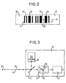
- Figur 2
- ein Beispiel für einen auf einem Codeträger angeordneten Code und
- Figur 3
- ein Blockdiagramm des Sende- und Empfangsteils der Codelesevorrichtung.
- Figure 1
- a simplified, purely schematic representation of a code reading device according to the invention,
- Figure 2
- an example of a code arranged on a code carrier and
- Figure 3
- a block diagram of the transmitting and receiving part of the code reading device.
Figur 1 zeigt in vereinfachter schematischer Weise eine Vorrichtung 10 zum Lesen eines auf einem Codeträger 12 vorgesehenen Codes 14 (siehe auch Figur 2).FIG. 1 shows in a simplified schematic manner a
Die Vorrichtung 10 umfaßt einen Sende-Empfangsteil 16 mit einem Lichtsender 18 und einer Lichtempfangsanordnung 20 sowie einer der Lichtempfangsanordnung 20 nachgeschaltenen Auswertelektronik 22 (siehe Figur 3). In dem Sende-Empfangsteil 16 kann auch eine Ablenkeinheit wie beispielsweise ein Spiegelrad integriert sein, um eine Scanbewegung des betreffenden Lichtstrahles über den Codeträger zu bewirken.The
Der Lichtsender 18 der Sende- und Empfangseinheit 16 liefert einen Lichtstrahl, im vorliegenden Fall einen Laserstrahl 24, durch den auf dem Codeträger 12 ein Lichtfleck 26 erzeugt wird, mit dem der Code 14 in Richtung des Pfeiles F abgetastet wird.The
Wie anhand von Figur 2 zu erkennen ist, handelt es sich bei dem Code 14 im vorliegenden Fall um einen Bar- oder Strichcode, der auf einer Oberfläche 28 des Codeträgers 12 vorgesehen ist.As can be seen from FIG. 2, the
Dieser Code 14 umfaßt mehrere auf die betreffende Oberfläche 28 des Codeträgers 12 aufgebrachte, beispielsweise aufgedruckte dunkle, balkenartige Felder 30 sowie helle balkenartige Felder 32, die unmittelbar durch die Oberfläche 28 des Codeträgers 18 gebildet sind.This
Der Lichtfleck 26 wird beispielsweise in der mit F bezeichneten Richtung (vgl. Fig. 1 und 2) quer über die balkenartigen Felder 30, 32 des Codes 14 geführt.The
Insbesondere die hellen Felder 32 reflektieren Licht zu der Lichtempfangsanordnung 20, wo dieses über eine Linse 34 auf ein Photodiode 36 fokussiert wird.In particular, the
Gemäß Figur 1 ist wenigstens eine, vorzugsweise diffus streuend reflektierende oder retroreflektierende Fläche 38 vorgesehen, durch die zumindest ein Teil des von den abgetasteten Codefeldern 30, 32 reflektierten, nicht auf die Lichtempfangsanordnung 20 treffenden Lichtes in den den Code 14 aufweisenden Abtastbereich zurückgeworfen wird, um dadurch den von der Lichtempfangsanordnung 20 erfaßten Lichtanteil zu erhöhen.According to FIG. 1, at least one, preferably diffusely scattering, reflecting or
Diese im vorliegenden Fall streuend reflektierende Fläche 38 ist nahe am Abtastbereich angeordnet, in dem der Abtastfleck 26 auf dem Code 14 abgebildet, d.h. der Code abgetastet wird.This
Die streuend reflektierende Fläche 38 kann beispielsweise eine weiße Fläche wie insbesondere eine durch weißes Papier oder dergleichen gebildete Fläche sein. Wie bereits erwähnt, kann auch eine retroreflektierende Fläche verwendet werden. Solche retroreflektierenden Flächen sind z.B. mit Reflexionsfolien leicht herstellbar. Mit einer derartigen retroreflektierenden Fläche wäre eine ähnliche Funktion wie mit weißem Papier erzielbar, und zwar auch bei einer größeren Entfernung der Fläche vom Codeträger. Eine solche retroreflektierende Fläche wäre daher insbesondere in dem Fall zweckmäßig, daß die Tiefenschärfe, d.h. der Bereich des Abstands des Optikkopfes zur Codeebene in der Anwendung variieren kann.The scattering reflecting
Wie anhand von Figur 1 zu erkennen ist, ist der vom SendeEmpfangsteil 16 ausgehende Abtastlaserstrahl 24 unter einem bestimmten Einfallswinkel α auf den Abtastbereich gerichtet. Die streuend reflektierende Fläche 38 ist dabei so angeordnet, daß bei angenommener Spiegelreflexion im Abtastbereich ein unter einem entsprechenden Austrittswinkel β vom Abtastbereich, insbesondere einem jeweiligen hellen Feld 32 reflektierte Lichtstrahl 40 auf die streuend reflektierende Fläche 38 auftritt.As can be seen from FIG. 1, the scanning
Durch die streuend reflektierende Fläche 38 wird das auftreffende Licht zumindest teilweise wieder zum Abtastbereich zurückgestreut, wo es insbesondere auch auf wenigstens ein helles Feld 32 auftrifft. Demzufolge gelangt ein entsprechender Lichtanteil ebenfalls durch Spiegelreflexion wiederum zur Lichtempfangsanordnung 20, wodurch der von der Lichtempfangsanordnung 20 erfaßte Lichtanteil insgesamt erhöht wird.Due to the scattering reflecting
Gemäß Fig. 3 umfaßt der Sende-Empfangsteil 16 einen Strahlenteiler 42 oder eine eng zusammenliegende Pupillenteilung (nicht dargestellt), durch den der vom Lichtsender 18 stammende Laserstrahl 24 zur Erzeugung des den Code abtastenden Lichtflecks 26 zum Codeträger hin umgelenkt wird und der den Empfangsstrahl 44 durchläßt, so daß dieser auf die Lichtempfangsanordnung 20 trifft. Im vorliegenden Fall verlaufen der Sende- und der Empfangsstrahl 24 bzw. 44 im wesentlichen zueinander parallel.3, the
Die Lichtempfangsanordnung 20 empfängt selbst dann noch Licht von den hellen Feldern 32, wenn diese durch eine spiegelnde Fläche ohne Streuvermögen gebildet sein sollten. Die fehlende Streureflektivität wird durch die streuend reflektierende Fläche 38 kompensiert, durch die ansonsten von der Lichtempfangsanordnung 20 nicht erfaßtes Licht in den Abtastbereich zurückgeworfen wird, von wo es zumindest teilweise zur Lichtempfangsanordnung 20 gelangt.The
Mit der erfindungsgemäßen Vorrichtung ist somit selbst dann ein fehlerfreies Lesen des Codes gewährleistet, wenn dieser auf einer blanken, polierten Metallfläche vorgesehen sein sollte, d.h. die hellen Felder durch eine solche Spiegelfläche gebildet sind.The device according to the invention thus ensures error-free reading of the code even if it should be provided on a bare, polished metal surface, ie the bright fields are formed by such a mirror surface.
- 1010th
- Vorrichtungcontraption
- 1212th
- CodeträgerCode carrier
- 1414
- Codecode
- 1616
- Sende-EmpfangsteilTransceiver part
- 1818th
- LichtsenderLight transmitter
- 2020th
- LichtempfangsanordnungLight receiving arrangement
- 2222
- AuswertelektronikEvaluation electronics
- 2424th
- Laserstrahllaser beam
- 2626
- LichtfleckSpot of light
- 2828
- Oberflächesurface
- 3030th
- dunkle Felderdark fields
- 3232
- helle Felderbright fields
- 3434
- Linselens
- 3636
- PhotodiodePhotodiode
- 3838
- reflektierende Flächereflective surface
- 4040
- reflektierter Lichtstrahlreflected light beam
- 4242
- StrahlteilerspiegelBeam splitter mirror
- 4444
- EmpfangsstrahlReceiving beam
Claims (12)
dadurch gekennzeichnet,
daß zumindest ein Teil des von den abgetasteten Codefeldern (32, 30) unterschiedlich reflektierten und nicht mehr zur Lichtempfangsanordnung (20) gelangenden Lichtes durch wenigstens eine reflektierende Fläche (38) in den Abtastbereich zurückgeführt wird, wobei dieses Licht durch die Codefelder (32, 30) erneut unterschiedlich reflektiert wird und danach der von der Lichtempfangsanordnung (20) erfaßte Kontrast in Abhängigkeit von den Codefeldern (32, 30) deutlich erhöht ist.Method for reading a code (14) provided on a code carrier (12) and consisting of light and dark fields (32, 30), in particular a bar code, in which the code (14) is generated with a light beam (18) generated by a light transmitter (18) 24) such as, in particular, a laser beam is scanned and the light which is returned to a light receiving arrangement (20) is evaluated,
characterized by
that at least a part of the light which is differently reflected by the scanned code fields (32, 30) and no longer reaches the light receiving arrangement (20) is returned to the scanning area through at least one reflecting surface (38), this light being passed through the code fields (32, 30 ) is reflected differently again and then the contrast detected by the light receiving arrangement (20) is significantly increased depending on the code fields (32, 30).
dadurch gekennzeichnet,
daß als reflektierende Fläche (38) eine streuend reflektierende Fläche verwendet wird.Method according to claim 1,
characterized by
that a scattering reflecting surface is used as the reflecting surface (38).
dadurch gekennzeichnet,
daß die reflektierende Fläche (38) nahe am Abtastbereich angeordnet wird.The method of claim 1 or 2,
characterized by
that the reflecting surface (38) is arranged close to the scanning area.
dadurch gekennzeichnet,
daß als reflektierende Fläche (38) eine weiße Fläche wie insbesondere eine durch weißes Papier oder dergleichen gebildete Fläche verwendet wird.Method according to one of the preceding claims,
characterized by
that a white surface such as in particular a surface formed by white paper or the like is used as the reflecting surface (38).
dadurch gekennzeichne,
daß als reflektierende Fläche (38) eine aus retroreflektierendem Material bestehende Fläche verwendet wird.Method according to one of the preceding claims,
characterized by
that a surface consisting of retroreflective material is used as the reflecting surface (38).
dadurch gekennzeichnet,
daß bei unter einem bestimmten Einfallswinkel (α) auf den Abtastbereich gerichtetem Abtastlichtstrahl (24) die reflektierende Fläche (38) so angeordnet wird, daß bei angenommener Spiegelreflexion im Abtastbereich der unter dem entsprechenden Austrittswinkel (β) vom Abtastbereich reflektierte Lichtstrahl (40) auf die reflektierende Fläche (38) auftrifft.Method according to one of the preceding claims,
characterized by
that at a certain angle of incidence (α) directed to the scanning area scanning light beam (24), the reflecting surface (38) is arranged so that with assumed mirror reflection in the scanning area, the light beam (40) reflected from the scanning area at the corresponding exit angle (β) onto the reflecting surface (38) strikes.
gekennzeichnet
durch wenigstens eine reflektierende Fläche (38), durch die zumindest ein Teil des von den abgetasteten Codefeldern (32, 30) unterschiedlich reflektierten und nicht mehr zur Lichtempfangsanordnung (20) gelangenden Lichtes in den Abtastbereich zurückgeworfen wird, wobei dieses Licht durch die Codefelder (32, 30) erneut unterschiedlich reflektiert wird und danach der von der Lichtempfangsanordnung (20) erfaßte Kontrast in Abhängigkeit von den Codefeldern (32, 30) deutlich erhöht ist.Device for reading a code (14), in particular a bar code, provided on a code carrier (12) consisting of light and dark fields (32, 30), with a light transmitter for generating a light beam (24) scanning the code (14), such as in particular a laser steel and a light receiving arrangement (20) for receiving the returned light, in particular for carrying out the method according to one of the preceding claims,
featured
by at least one reflecting surface (38) through which at least part of the light which is differently reflected by the scanned code fields (32, 30) and no longer reaches the light receiving arrangement (20) is thrown back into the scanning area, this light again being reflected differently by the code fields (32, 30) and then the contrast detected by the light receiving arrangement (20) is significantly increased depending on the code fields (32, 30).
dadurch gekennzeichnet,
daß die reflektierende Fläche (38) eine streuend reflekierende Fläche ist.Device according to claim 7,
characterized by
that the reflecting surface (38) is a scattering reflecting surface.
dadurch gekennzeichnet,
daß die reflektierende Fläche (38) nahe am Abtastbereich angeordnet ist.Device according to claim 7 or 8,
characterized by
that the reflecting surface (38) is arranged close to the scanning area.
dadurch gekennzeichnet,
daß die reflektierende Fläche (38) eine weiße Fläche wie insbesondere eine durch weißes Papier oder dergleichen gebildete Fläche ist.Device according to one of the preceding claims,
characterized by
that the reflecting surface (38) is a white surface, in particular a surface formed by white paper or the like.
dadurch gekennzeichnet,
daß die reflektierende Fläche (38) eine aus retroreflektierendem Material bestehende Fläche ist.Device according to one of the preceding claims,
characterized by
that the reflecting surface (38) is a surface consisting of retroreflective material.
dadurch gekennzeichnet,
daß der Abtastlichtstrahl (24) unter einem bestimmten Einfallswinkel (α) auf den Abtastbereich gerichtet und die reflektierende Fläche (38) so angeordnet ist, daß bei angenommener Spiegelreflexion im Abtastbereich der unter dem entsprechenden Austrittswinkel (β) vom Abtastbereich reflektierte Lichtstrahl (40) auf die reflektierende Fläche (38) auftrifft.Device according to one of the preceding claims,
characterized by
that the scanning light beam (24) is directed at a certain angle of incidence (α) onto the scanning area and the reflecting surface (38) is arranged in such a way that with assumed mirror reflection in the scanning area the light beam (40) reflected from the scanning area at the corresponding exit angle (β) strikes the reflecting surface (38).
Applications Claiming Priority (2)
| Application Number | Priority Date | Filing Date | Title |
|---|---|---|---|
| DE19619479 | 1996-05-14 | ||
| DE19619479A DE19619479A1 (en) | 1996-05-14 | 1996-05-14 | Method and device for reading a code provided on a code carrier |
Publications (2)
| Publication Number | Publication Date |
|---|---|
| EP0807899A2 true EP0807899A2 (en) | 1997-11-19 |
| EP0807899A3 EP0807899A3 (en) | 2000-02-23 |
Family
ID=7794324
Family Applications (1)
| Application Number | Title | Priority Date | Filing Date |
|---|---|---|---|
| EP97107820A Withdrawn EP0807899A3 (en) | 1996-05-14 | 1997-05-13 | Method and apparatus for reading a code on a code carrying means |
Country Status (3)
| Country | Link |
|---|---|
| US (1) | US5929424A (en) |
| EP (1) | EP0807899A3 (en) |
| DE (1) | DE19619479A1 (en) |
Families Citing this family (2)
| Publication number | Priority date | Publication date | Assignee | Title |
|---|---|---|---|---|
| US6661521B1 (en) * | 1998-09-11 | 2003-12-09 | Robotic Vision Systems, Inc. | Diffuse surface illumination apparatus and methods |
| US6611318B2 (en) | 2001-03-23 | 2003-08-26 | Automatic Timing & Controls, Inc. | Adjustable mirror for collimated beam laser sensor |
Family Cites Families (12)
| Publication number | Priority date | Publication date | Assignee | Title |
|---|---|---|---|---|
| US4201910A (en) * | 1978-03-27 | 1980-05-06 | Innovation Industries, Inc. | Photosensor assembly |
| US5545889A (en) * | 1985-02-28 | 1996-08-13 | Swartz; Jerome | Portable laser diode scanning head |
| US4766297A (en) * | 1987-01-08 | 1988-08-23 | Recognition Equipment Incorporated | Dual mode stationary and portable scanning system |
| US4960984A (en) * | 1988-02-04 | 1990-10-02 | Westinghouse Electric Corp. | Method and apparatus for reading lased bar codes on shiny-finished fuel rod cladding tubes |
| JPH0786899B2 (en) * | 1988-04-28 | 1995-09-20 | 日本車輌製造株式会社 | Barcode reading method |
| US5594228A (en) * | 1988-08-25 | 1997-01-14 | Symbol Technologies, Inc. | Self-checkout, point-of-transaction system including deactivatable electro-optically coded surveillance tags |
| US5216232A (en) * | 1990-09-10 | 1993-06-01 | Metrologic Instruments, Inc. | Projection laser scanner producing a narrow scan volume |
| DE69232291T2 (en) * | 1991-10-29 | 2002-10-31 | Denso Corp., Kariya | INFORMATION READER |
| JP3483217B2 (en) * | 1994-02-08 | 2004-01-06 | チノン株式会社 | Image reading device |
| JP3183767B2 (en) * | 1994-02-21 | 2001-07-09 | 富士通株式会社 | Laser beam scanning device |
| NL9401302A (en) * | 1994-08-11 | 1996-03-01 | Scantech Bv | Barcode scanner. |
| US5610385A (en) * | 1995-02-23 | 1997-03-11 | Ncr Corporation | Optical bar code scanner which produces substantially perpendicular scan lines |
-
1996
- 1996-05-14 DE DE19619479A patent/DE19619479A1/en not_active Withdrawn
-
1997
- 1997-05-13 EP EP97107820A patent/EP0807899A3/en not_active Withdrawn
- 1997-05-13 US US08/855,177 patent/US5929424A/en not_active Expired - Fee Related
Also Published As
| Publication number | Publication date |
|---|---|
| US5929424A (en) | 1999-07-27 |
| EP0807899A3 (en) | 2000-02-23 |
| DE19619479A1 (en) | 1997-11-20 |
Similar Documents
| Publication | Publication Date | Title |
|---|---|---|
| EP0354362B1 (en) | Method of marking a bottle with, and optically reading, readable codes | |
| DE69304348T2 (en) | COIN DETECTOR | |
| DE2131467C3 (en) | Lichtablenkvorriehtung for parallel displacement of a light beam | |
| DE10341548A1 (en) | Optoelectronic detection device | |
| DE69124052T2 (en) | Laser beam stripe code reader | |
| DE602004005083T2 (en) | A banknote detection unit for a banknote recognition device | |
| EP1287496A1 (en) | Device for verifying documents | |
| EP1207491B1 (en) | Optoelectronic device | |
| DE3750600T2 (en) | Coding reader. | |
| EP0516927A2 (en) | Barcode system | |
| EP0807899A2 (en) | Method and apparatus for reading a code on a code carrying means | |
| EP3070496A1 (en) | Polygon scanner and method for recording objects | |
| EP1498747B1 (en) | Optoelectronic device | |
| DE69732565T2 (en) | Apparatus and method for reading an optical code | |
| DE19700281A1 (en) | Optical code reader with an optical scanner | |
| CH663285A5 (en) | OPTICAL SCANNER. | |
| DE69930984T2 (en) | Optical device for scanning and encoding a bar code | |
| EP0967458B2 (en) | Opto-electronic sensor | |
| EP0988232A1 (en) | Label sensor | |
| DE20006317U1 (en) | Device for recognizing an object | |
| DE2163949C3 (en) | Reading device for optically recognizable characters | |
| DE19605505C2 (en) | Optical scanning arrangement | |
| DE2552331C3 (en) | Scanning device | |
| DE10101985A1 (en) | Optoelectronic arrangement feeds at least some of light reflected back from outlet window to receiver element whose resulting signal forms deflection synchronizing signal | |
| DE102004053293A1 (en) | Scanning device for barcodes |
Legal Events
| Date | Code | Title | Description |
|---|---|---|---|
| PUAI | Public reference made under article 153(3) epc to a published international application that has entered the european phase |
Free format text: ORIGINAL CODE: 0009012 |
|
| AK | Designated contracting states |
Kind code of ref document: A2 Designated state(s): DE FR GB |
|
| PUAL | Search report despatched |
Free format text: ORIGINAL CODE: 0009013 |
|
| AK | Designated contracting states |
Kind code of ref document: A3 Designated state(s): DE FR GB |
|
| STAA | Information on the status of an ep patent application or granted ep patent |
Free format text: STATUS: THE APPLICATION IS DEEMED TO BE WITHDRAWN |
|
| 18D | Application deemed to be withdrawn |
Effective date: 20000824 |