EP0807727A2 - Pièce de construction - Google Patents
Pièce de construction Download PDFInfo
- Publication number
- EP0807727A2 EP0807727A2 EP97303304A EP97303304A EP0807727A2 EP 0807727 A2 EP0807727 A2 EP 0807727A2 EP 97303304 A EP97303304 A EP 97303304A EP 97303304 A EP97303304 A EP 97303304A EP 0807727 A2 EP0807727 A2 EP 0807727A2
- Authority
- EP
- European Patent Office
- Prior art keywords
- spacer
- building
- batten
- building component
- base element
- Prior art date
- Legal status (The legal status is an assumption and is not a legal conclusion. Google has not performed a legal analysis and makes no representation as to the accuracy of the status listed.)
- Granted
Links
Images


Classifications
-
- E—FIXED CONSTRUCTIONS
- E04—BUILDING
- E04B—GENERAL BUILDING CONSTRUCTIONS; WALLS, e.g. PARTITIONS; ROOFS; FLOORS; CEILINGS; INSULATION OR OTHER PROTECTION OF BUILDINGS
- E04B9/00—Ceilings; Construction of ceilings, e.g. false ceilings; Ceiling construction with regard to insulation
- E04B9/18—Means for suspending the supporting construction
-
- E—FIXED CONSTRUCTIONS
- E04—BUILDING
- E04F—FINISHING WORK ON BUILDINGS, e.g. STAIRS, FLOORS
- E04F15/00—Flooring
- E04F15/02—Flooring or floor layers composed of a number of similar elements
- E04F15/024—Sectional false floors, e.g. computer floors
- E04F15/02447—Supporting structures
- E04F15/02458—Framework supporting the panels
-
- E—FIXED CONSTRUCTIONS
- E04—BUILDING
- E04F—FINISHING WORK ON BUILDINGS, e.g. STAIRS, FLOORS
- E04F15/00—Flooring
- E04F15/22—Resiliently-mounted floors, e.g. sprung floors
-
- E—FIXED CONSTRUCTIONS
- E04—BUILDING
- E04B—GENERAL BUILDING CONSTRUCTIONS; WALLS, e.g. PARTITIONS; ROOFS; FLOORS; CEILINGS; INSULATION OR OTHER PROTECTION OF BUILDINGS
- E04B9/00—Ceilings; Construction of ceilings, e.g. false ceilings; Ceiling construction with regard to insulation
- E04B9/18—Means for suspending the supporting construction
- E04B2009/186—Means for suspending the supporting construction with arrangements for damping vibration
Definitions
- the present invention relates to a building component and in particular to a component for use in the formation of a floor, wall or ceiling, and to floors, walls or ceilings made using the component.
- the present invention also relates to a method of constructing a floor, wall or ceiling.
- the state of the art in so far as it relates to flooring is outlined in GB 2,126,265 in which there is described a flooring component which is intended to be located on the structural member over which the floor is to be laid.
- the flooring component comprises a pair of base elements on the upper surface of which there is mounted a pair of spaced, longitudinally extending support members.
- the base elements and support members together define a cradle which is adapted to accommodate a support batten over which the flooring layer is to be applied.
- a resilient material is mounted on a lower surface of the base element such that in use the resilient material contacts the underlying structural member while levelling of the support batten is effected by interposing spacers between the base element and an underside of the support batten.
- a modification of the above flooring component is disclosed in GB 2,185,048 in which there is described an arrangement in which the pair of support members are each formed with a discontinuity. In this way a channel is provided capable of accommodating a second support batten extending generally at right angles to the first.
- the pair of support members are typically formed of a rigid material such as wood or metal and are therefore incapable of flexing to accommodate support battens of differing widths. Indeed, if the support batten has a width which is greater than the distance between the support members, the batten simply will not fit into the cradle. Likewise, if the support batten has a width which is significantly less than the distance between the side support members, there will be a tendency for the batten to move laterally within the cradle and thereby act as a source of additional noise as people, or objects, move, or are moved, over the overlying flooring layer.
- the only way of adjusting the height of the supporting batten is by inserting spacers between the batten and the cradle in the longitudinal direction of the batten. This means that if the support batten is not at the correct height it must first be lifted out of the cradle to allow a spacer to be inserted before the support batten is then reintroduced into the cradle and the height reassessed. It would be far more convenient if a method could be found of introducing spacers between the base element and the supporting batten which did not require the supporting batten to be continually lifted out of the cradle.
- the supporting cradles have been manufactured with a base of a thickness appropriate to raise the floor the necessary height.
- this is inconvenient as it involves the manufacture of a number of different sized cradles.
- the end user cannot easily alter spacing between the floor and the underlying structural member on site should an alternate spacing be required from that originally envisaged.
- a building component in combination with one or more spacers, the building component comprising a base element adapted to be positioned on a surface of a building structure and a pair of mutually spaced side members which project from the base element to define a longitudinal channel for the receipt of a supporting batten to which a further surface layer may be secured, the building component being adapted to allow the insertion of the or each spacer between the base element and the supporting batten in a direction transverse to the longitudinal channel.
- a building component in combination with a spacer, the building component comprising a base element adapted to be positioned on a surface of a building structure and a pair of mutually spaced side members which project from the base element to define a longitudinal channel, and the spacer comprising a base section and a pair of mutually spaced side walls, the base section of the spacer being adapted to overlie the base element of the building component.
- a building component comprising a base element adapted to be positioned on a surface of a building structure; a pair of mutually spaced side members which project from the base element to define a longitudinal channel for the receipt of a supporting batten to which a further surface layer may be secured; and one or more frangible regions spaced at intervals along the length of the channel.
- one or both of the side members may be formed of resilient material.
- the base element may be provided with a layer of resilient material on a surface of the base element such that, in use, the resilient material is interposed between the base element and the building structure.
- the base element may be provided with a layer of resilient material on a surface of the base element such that, in use, the resilient material is interposed between the base element and the supporting batten.
- the base element is formed of resilient material.
- the building component is integrally formed of resilient material.
- the building component may be formed of rubber.
- the building component is formed of a plurality of rubber crumbs which are bound together in a matrix by adhesive.
- a floor, wall or ceiling comprising a plurality of building components and spacers in accordance with any of claims 1 to 22 or any of claims 25 to 28 when dependent on any of claims 1 to 22, the building components being positioned in a plurality of spaced rows over a surface of a building structure and longitudinally spaced within each row with the channels aligned to define a longitudinal batten path, one or more supporting battens disposed along said batten path with the spacers interposed between said supporting battens and said building components, and one or more elements of a surface layer secured to the supporting batten to form said floor, wall or ceiling.
- a floor, wall or ceiling comprising a plurality of building components in accordance with claim 23 or any of claims 24 to 28 when dependent on claim 23, the building components being positioned in a plurality of spaced rows over a surface of a building structure and longitudinally spaced within each row with the channels aligned to define a longitudinal batten path, one or more supporting battens disposed along said batten path, and one or more elements of a surface layer secured to the supporting battens to form said floor, wall or ceiling.
- a method of constructing a floor, wall or ceiling comprising the steps of positioning in a plurality of spaced rows over a surface of a building structure a plurality of building components in accordance with any of claims 1 to 22 or any of claims 25 to 28 when dependent on any of claims 1 to 22, spacing the building components longitudinally within each of said rows and allowing the channels defined by the building components so as to define a longitudinal batten path; inserting one or more battens along said batten path; inserting one or more spacers between said supporting battens and said building components in a direction transverse to said batten path; and securing one or more elements of a surface layer to the supporting battens to form said floor, wall or ceiling.
- a method of constructing a floor, wall or ceiling comprising the steps of providing a plurality of building components in accordance with claim 23 or any of claims 24 to 28 when dependent on claim 23; reducing one or more of the building components to the desired length by breaking one or more of said frangible regions; positioning said building components in a plurality of spaced rows over a surface of a building structure; spacing the building component longitudinally within each of said rows and aligning the channels defined by the building components so as to define a longitudinal batten path; inserting one or more supporting battens along said batten path; and securing one or more elements of a surface layer to the supporting battens to form said floor, wall or ceiling.
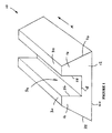
- a building component 10 comprising a base element 12 and two upwardly projecting side members 14 and 16.
- the building component 10 may be of any convenient dimension in the longitudinal direction X however, in cross-section and as shown in Figure 2, the base element 12 can be seen to be bounded by an upper surface 18 and a somewhat larger lower surface 20 as well as by inclined side walls 22 and 24.
- the inclined side walls 22 and 24 subtend an included angle at the lower surface 20 of between 60° and 80° and extend upwardly from the lower surface to merge with, and partially define, a respective one of the upwardly projecting side members 14 or 16.
- the upwardly projecting side members 14 and 16 are each defined by a respective one of a pair of inner side walls 26 and 28 which extend upwardly from opposite ends of the upper surface 18 as well as by a respective top surface 30 or 32.
- the top surfaces 30 and 32 occupy planes which are substantially parallel both to each other and to those occupied by the upper and lower surfaces 18 and 20 while the two inner side walls 26 and 28 occupy planes which extend substantially perpendicularly to that containing the upper surface 18 so as to thereby define a square based channel 34.
- the two inner side walls 26 and 28 are preferably spaced apart by a distance of between 3cm and 5.5cm so as to enable the square based channel 34 to accommodate a variety of supporting battens. However, in a currently preferred embodiment the inner side walls 26 and 28 are spaced apart by a distance of approximately 4cm.
- a plurality of such building components 10 are placed on an underlying structure each with their respective lower surfaces 20 in contact with the structure.
- the building components 10 are positioned in a number of spaced apart rows.
- the building components 10 are again spaced, this time longitudinally, with their respective square based channels 34 aligned so as to define a longitudinal batten path.
- a plurality of supporting battens are then introduced to the longitudinal batten paths and pushed down between the outwardly projecting side members 14 and 16. If, for some reason, the supporting battens are not at a desired height, one or more height adjusting spacers 40 may be introduced into the square based channels 34 between the supporting battens and the upper surface 18 of the base element 12. Once the supporting battens are in place the desired flooring layer is then laid over the top of the supporting battens and secured in place.
- one, but preferably both, of the upwardly projecting side members 14 and 16 are formed of resilient material.
- the side members are able to deform outwardly to accommodate an oversized supporting batten.
- the building component 10 may be dimensioned so that the upwardly projecting side members 14 and 16 deform sufficiently to grip a standard sized supporting batten and thereby hold the batten in place.
- the upwardly projecting side members 14' and 16' are provided on the inner side walls 26' and 28' with one or more laterally extending, resilient projections or ribs 36' specifically designed to engage and grip a supporting batten received within the square based channel 34'.
- the upwardly projecting side members 14 and 16 By forming the upwardly projecting side members 14 and 16 of resilient material, many of the manufacturing problems associated with the components of the prior art may be overcome. For example, it no longer becomes necessary to manufacture the building component 10 to such high tolerances since the ability of the upwardly projecting side members 14 and 16 to deform outwardly enables standard sized supporting battens to be accommodated by square based channels 34 of varying widths. Alternatively, a square based channel 34 of predetermined dimensions may be used to accommodate a variety of different supporting battens.
- the resilient nature of the upwardly projecting side members 14 and 16 enables the building component 10 to grip the supporting batten and thereby hold it securely in place without the need for additional fastening means or adhesives. Furthermore, by providing upwardly projecting side members 14 and 16 that are formed of resilient material, the building component 10 is able to absorb any lateral vibrations that are applied to it via the supporting batten and so serves to reduce the transmission of noise within the cavity defined between the flooring layer and the underlying structure.
- the base element 12 is additionally provided on its lower surface 20 with a layer of resilient material.
- the building component 10 may also absorb vibrations having a component in a vertical plane and may once again serve to reduce the transmission of noise in the cavity defined between the flooring layer and the underlying structure.
- the layer of resilient material may be provided on the upper surface 18. This again has the effect of absorbing vibrations having a component in a vertical plane.
- the entire base element 12 may be formed of resilient material. Once again this provides the building component 10 with improved sound insulating properties.
- the entire building component 10 may be formed of the same material to produce an integral structure. This has the effect of greatly simplifying the manufacturing process which in turn reduces the manufacturing cost.
- the building component 10 is formed of rubber crumbs each having a nominal diameter of between 1mm and 4mm which are bound together by a non-water soluble adhesive to form a matrix.
- a non-water soluble adhesive to form a matrix.
- the building component 10 may be formed in a mould under a nominal closing pressure of, say, 40kg.
- a one piece building component may be formed of resilient material in a number of different ways and furthermore that those building components may have a variety of hardnesses depending on the applications in which they are to find use.
- the building component may equally be formed of cork or polystyrene or indeed a mixture of one or both of these materials and rubber.
- one of the advantages of using a resilient material such as rubber is that, unlike the building components of the prior art which have tended to be made of wood or metal, the building component resists vibration and so does not "squeak" when people, or objects, move, or are moved, over the flooring layer above.
- Another advantage is that building components formed of resilient material are that much more difficult to damage or break either in use or in storage prior to use. Accordingly, the number of building components lost or damaged due to what may be termed "natural wastage" is considerably reduced.
- Yet another advantage of forming the building component entirely of a material such as rubber is that it is unaffected by water. Thus if for whatever reason water should penetrate into the cavity defined between the flooring layer and the underlying structure it at least will not cause any damage to the building components supporting the battens.
- the building component 10 may be of any convenient length in the longitudinal direction X.
- the building component entirely of a material such as rubber it is possible for a preformed building component to be cut to size on site using nothing more than a sharp knife. This again has implications for manufacturing costs since the building components may be formed in standard lengths and only cut to size when details of their specific use are known.
- each building component 10 may again be formed in standard lengths but be provided with an number of frangible regions along that length thereby enabling part of the component to be torn away to leave a remainder which is of a length suited to the application in hand. In this way even the use of standard workman tools, such as sharp knives, can be avoided.
- the building components 10 may be moulded in a grid of x building components by y building components with a frangible region between each building component and its neighbours, thereby enabling any selected building component to be torn away or otherwise removed from the grid.
- Another advantage of forming the building component solely of a material such as rubber is that the shape of the building component may easily be modified to fit individual situations, and may be resized on site simply by the use of a sharp knife or by a tearing action. For example, a portion of one of the upper side members may easily be removed from the building component so as to accommodate pipework laid in close proximity to a support batten.
- the building component 10" is shown to include two apertures 38" in the upwardly projecting side member 16". If desired, similar apertures may also be provided in the other upwardly projecting side member 14" and, although not shown in Figure 4 these apertures can, if so desired, be in line with the first apertures 38".
- a building component 10" having one or more apertures 38" in the upwardly projecting side members 14" and 16" it is possible to insert a height adjusting spacer 40" between the supporting batten and the base element 12" even after the supporting batten has been received within the square based channel 34". This greatly simplifies the task of ensuring that the supporting batten, and hence the flooring layer laid on top of the supporting batten, is spaced at the desired distance from the underlying structure.
- the height adjusting spacer 40" may be provided with one or more barbs 42" to enable the spacer to engage and grip the building component 10" once it has been inserted through the aperture 38". This provides the advantage of avoiding the use of an adhesive or some other means in order to hold the height adjusting spacer 40" in place. Whilst the spacer 40" shown in Figure 5A has barbs 42" which extend in the same plane as the rest of the spacer, it will be apparent to those skilled in the art that the barbs 42" may also extend in other planes.
- the height adjusting spacer 40" may be made slightly oversize for the dimensions of the square based channel 34" so that, having been inserted through one of the apertures 38", it is held in place by virtue of the resilient nature of the upwardly projecting side members 14" and 16".
- the height adjusting spacer 40" may be made slightly oversize for the dimensions of the apertures 38" so that, once again, having been squeezed through an aperture 38" it is held in place by the resilience of the side members 14" and 16".
- the height adjusting spacer 40' is of a width A at both ends, broadening out to a central width B, where A is less than B and B slightly greater than the width of the aperture 38".
- A is less than B and B slightly greater than the width of the aperture 38.
- the spacer is loosely held in place with the central portion of width B resting within the area of the square based channel 34", and the ends of the spacer of width A extending into the apertures 38".
- the change in width of the spacer is not at a perpendicular step, but along chamfered edges 44'.
- One of the advantages of the spacer shown in Figure 5B over that, say, shown in Figure 5A is that it is generally planar and so can be stacked on top of another similar spacer to provide a composite spacer of increased height.
- the spacers themselves may be formed of a resilient material in preference to the building component.
- the building component 10 is provided with upwardly projecting side members 14 and 16 which are shaped so as to define not only a first square based channel 34 but also a second square based channel 44 which extends in a direction transverse to the first square based channel.
- the building component 10 may be used to simultaneously receive two supporting battens which extend transversely of each other.
- the upwardly projecting side members 14 and 16 may be shaped so that the second square based channel 44 extends substantially at right angles to the first.
- either the first or second square base channel may also serve to define apertures through which spacers may be inserted in a direction transverse to the supporting batten to be raised.
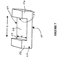
- FIG. 7 there is shown another design of spacer 50 comprising a base section 52 and two upwardly projecting side walls 54 and 56.
- the base section 52 is of generally rectangular cross-section and has a length K, a width M and a height H.
- the two upwardly projecting side walls 54 and 56 define respective opposing surfaces 55 and 57 which are spaced a distance L apart.
- the base section 52 and the two upwardly projecting side walls 54 and 56 together define a substantially U-shaped channel in which the base of the channel 58 (defined by that portion of an upper surface of the base section which extends between the two side walls) has an area of L x M.
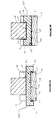
- Figure 8A and 8B show two alternative ways in which spacers of the same general configuration as that shown in Figure 7 but of different specific dimensions may be used to raise a supporting batten above the level of the base element 12. Such an increase in height may be desirable, for example, to accommodate a layer of sound insulating material between the floor and the underlying structural member.
- Figure 8A shows the spacer 50 resting with the base section 52 overlying the base element 12 of the building component with the base of the channel 58 in engagement with the upper surface 18 and with the spacer side 54 and 56 extending downwardly adjacent side walls 22 and 24.
- the supporting batten rests upon what in Figure 7 is the lower surface of the base section 52 and is thus raised by a distance H above the base element 12 equivalent to the thickness of the spacer base section 52.
- the base element 12 is of a resilient character, and the distance L between the spacer side walls 54 and 56 is slightly narrower than the corresponding width of the base element.
- the resilient nature of the base element 12 thus enables the building component to securely gripped by the spacer 50.
- one or both of the spacer side walls 54, 56 could be of a resilient character to achieve the same result.
- the embodiment of Figure 8A provides the advantage of avoiding the use of an adhesive or some other means in order to hold the spacer in place.
- the base section 52 is formed in such a way that the width M is slightly oversized compared to the apertures 38 of the building component.
- the spacer 50 may be held securely in position by the resilient nature of one or both of the spacer and building component side members 14, 16.
- the side walls 54 and 56 are seen to extend substantially perpendicularly away from the base section 52 in order to fit securely around the perpendicular edges of the base element 12.
- the side walls 54 and 56 could, of course, also be appropriately inclined with respect to the base section 52 so as to once more locate the spacer with respect to the building component.
- the spacer base section 52 once again overlies the base element 12 of the building component. However, this time it is the lower surface of the base section 52 which is in engagement with the upper surface 18 and the side walls 54, 56 extending upwardly away from the base element 12 rather than downwardly. As a result the spacer provides a channel for the supporting batten to rest within defined by surfaces 55, 57 and 58.
- the spacer may be made of resilient material and the distance L between the side walls 54, 56 may be slightly undersized compared to the supporting batten so as to ensure that the batten is securely gripped.
- the spacer may be formed with the dimension M slightly oversized with respect to the apertures 38 of the building component. In this way, provided one or both of the spacer and the building component are resilient, the spacer may be held in place by the side members 14 and 16.
- the spacer 50 illustrated in Figure 7 is formed so that the distance L is such as to enable the U-shaped channel defined by the base section 52 and the side walls 54 and 56 to receive a supporting batten.
- the spacer width M is selected so as to equal the distance L thereby rendering the base of the channel 58 square.
- a first spacer may be positioned on the building component as illustrated in either of Figures 8A or Figure 8B, the support batten removed and a second spacer of identical construction placed at right angles on top the first such that the base of the channel 58 of the second spacer either in contact with what in Figure 7 is the lower surface of the base section 52 of the first spacer (if the first spacer is in the orientation shown in figure 8A) or the base of the channel 58 of the first spacer (if the first spacer is in the orientation shown in Figure 8B).
- the supporting batten may then be placed on top of what in Figure 7 is the lower surface of the base section 52 of the second spacer and as a result is raised by a height 2H equivalent to the combined height of the two spacers.
- FIG. 9A the two embodiments of Figures 8A and 8B are effectively combined into a single integral unit.
- This further embodiment 50' comprises a base section 52', two upwardly projecting side walls 54' and 56' spaced a distance L' apart so as to accommodate a supporting batten, and two downwardly projecting side walls 54" and 56" spaced a distance L" apart so as to be capable of being seated on a building component base element 12.
- the spacer is effectively composed of two of the spacers illustrated in Figure 7 placed back-to-back.
- This embodiment thus comprises a base section 52, two upwardly projecting side walls 54' and 56' spaced a distance L apart so as to accommodate a supporting batten, and two downwardly projecting side walls 54" and 56" also spaced a distance L apart.
- the base section is also of width L so that the base of the 2 U-shaped channels 58' and 58" defined by the base section 52 and the two pairs of side walls 54' and 56' and 54" and 56" are both square.
- the spacer of this embodiment may be positioned on top of either of the spacers illustrated in Figures 8A or 8B, in the same manner as has been previously described.
- the surfaces 55', 57' and 58' define an upper U-shaped channel either for receiving a supporting batten or for receiving a further H-shaped spacer of identical construction but oriented at right angles to the first.
- planar or barbed spacers illustrated in Figures 5A and 5B may also be used in conjunction with the H-shaped or U-shaped spacers of Figures 7 to 9B in order to "fine tune" the supporting batten to be the desired distance from the structural member.
- the present building component 10 has been described almost exclusively in conjunction with floors, it will be apparent to those skilled in the art that it may also find use with walls and ceilings in much the same way.
- the lower surface 20 is placed in contact with the underlying structure of the wall or ceiling and secured thereto by any suitable means.
- a supporting batten is then introduced into the square based channel 34 and the distance between the supporting batten and the underlying structure adjusted by inserting one or more spacers between the batten and the base element 12. Once the supporting batten is at the desired distance from the underlying structure one or more surface panels are secured to the supporting batten to define the desired wall or ceiling.
- the building component 10 may incorporate a metal reinforcing member 46 of substantially C-shaped cross-section.
- the reinforcing member 46 is preferably embedded within the building component 10 with the limbs of the reinforcing member 48 and 50 extending on either side of the square based channel 34 and generally parallel to the inner sidewalls 26 and 28.
- the building component 10 may be secured to the underlying ceiling structure by means of a suitable fastener 52 passing through an aperture in the reinforcing member 46 while the supporting batten may be retained within the square based channel 34 by further fasteners 54 and 56 passing through the limbs of the reinforcing member 48 and 50.
- the present building component 10 has been described as being of a particular cross-section, it will be apparent to those skilled in the art that the present invention is not limited to the cross-sectional shape shown in the accompanying drawings.
- the side walls 22 and 24 need not subtend an included angle at the lower surface 20 of between 60° and 80°. Instead they may extend substantially perpendicularly to the lower surface 20 so as to no longer be inclined.
- the side members 14 and 16 have been described as being capable of deforming resiliently by virtue of the material of which they are formed in a direction transverse to that of the square based channel 34, it will again be apparent to those skilled in the art that this need not be the case.
- the side members may be provided with a mechanical construction which enables them to deform resiliently in the same direction whilst they themselves are formed of a non-resilient material.
- the present invention is not limited to a building component comprising solely one pair of mutually spaced side members 14 and 16.
- the building component may be provided with a third side member which extends in a direction parallel to the other two. This third side member may be spaced from the central "side member" so as to define a second square based channel of differing width but which nevertheless extends in the same direction as the first. In this way the one building component may be used to accommodate supporting battens of greatly differing dimensions.
Landscapes
- Engineering & Computer Science (AREA)
- Architecture (AREA)
- Civil Engineering (AREA)
- Structural Engineering (AREA)
- General Engineering & Computer Science (AREA)
- Physics & Mathematics (AREA)
- Electromagnetism (AREA)
- Floor Finish (AREA)
- Transition And Organic Metals Composition Catalysts For Addition Polymerization (AREA)
- Finishing Walls (AREA)
- Building Environments (AREA)
- Prostheses (AREA)
Applications Claiming Priority (2)
| Application Number | Priority Date | Filing Date | Title |
|---|---|---|---|
| GB9610158 | 1996-05-15 | ||
| GB9610158A GB2314351B (en) | 1996-05-15 | 1996-05-15 | Supports for floor, wall or ceiling claddings |
Publications (4)
| Publication Number | Publication Date |
|---|---|
| EP0807727A2 true EP0807727A2 (fr) | 1997-11-19 |
| EP0807727A3 EP0807727A3 (fr) | 1998-04-01 |
| EP0807727B1 EP0807727B1 (fr) | 2003-12-10 |
| EP0807727B8 EP0807727B8 (fr) | 2005-08-17 |
Family
ID=10793745
Family Applications (1)
| Application Number | Title | Priority Date | Filing Date |
|---|---|---|---|
| EP97303304A Expired - Lifetime EP0807727B8 (fr) | 1996-05-15 | 1997-05-15 | Kit comprenant une pièce de construction et au moins une cale |
Country Status (5)
| Country | Link |
|---|---|
| US (1) | US6026623A (fr) |
| EP (1) | EP0807727B8 (fr) |
| AT (1) | ATE256232T1 (fr) |
| DE (1) | DE69726640D1 (fr) |
| GB (2) | GB2314351B (fr) |
Cited By (4)
| Publication number | Priority date | Publication date | Assignee | Title |
|---|---|---|---|---|
| GB2358881A (en) * | 2000-01-18 | 2001-08-08 | Instafibre Ltd | Building component |
| GB2403486A (en) * | 2003-07-04 | 2005-01-05 | Michael Earls | Levelling system for use with floor joists and battens |
| WO2006059058A1 (fr) * | 2004-12-03 | 2006-06-08 | William Charles Ansell | Berceaux de nivellement pour support de latte et procede de support de latte |
| CN1981103B (zh) * | 2004-07-06 | 2010-05-26 | 丹尼斯·雷蒙德·普劳特 | 限位装置 |
Families Citing this family (26)
| Publication number | Priority date | Publication date | Assignee | Title |
|---|---|---|---|---|
| GB9624407D0 (en) * | 1996-11-23 | 1997-01-08 | Danskin Flooring Systems Ltd | Flooring components |
| GB2341403B (en) * | 1998-09-11 | 2003-02-05 | Hillaldam Coburn Ltd | A support |
| GB2354536B (en) * | 1999-03-04 | 2002-04-03 | Danskin Flooring Systems Ltd | Improved building system |
| GB9904840D0 (en) * | 1999-03-04 | 1999-04-28 | Danskin Flooring Systems Ltd | Improved building system |
| US6405507B1 (en) | 1999-04-21 | 2002-06-18 | Milton Edward "L" | Channel members |
| US20020129001A1 (en) * | 2000-12-12 | 2002-09-12 | Levkoff Jonathan S. | Method and system for assimilation, integration and deployment of architectural, engineering and construction information technology |
| GB2390619A (en) * | 2001-03-17 | 2004-01-14 | Danskin Flooring Systems Ltd | Sound-proofed floor |
| GB0106650D0 (en) * | 2001-03-17 | 2001-05-09 | Danskin Flooring Systems Ltd | Improved building system |
| WO2005031080A1 (fr) * | 2003-10-01 | 2005-04-07 | Bluescope Steel Limited | Cloison acoustique et element de fixation utilise dans celle-ci |
| US8272618B2 (en) * | 2004-11-30 | 2012-09-25 | The Boeing Company | Minimum bond thickness assembly feature assurance |
| US20060115320A1 (en) * | 2004-11-30 | 2006-06-01 | The Boeing Company | Determinant assembly features for vehicle structures |
| US7555873B2 (en) * | 2004-11-30 | 2009-07-07 | The Boeing Company | Self-locating feature for a pi-joint assembly |
| DE202006005678U1 (de) * | 2006-04-05 | 2006-06-14 | Richter-System Gmbh & Co Kg | Befestigungseinrichtung für Bauelemente des Trockenbaus |
| US20070246974A1 (en) * | 2006-04-24 | 2007-10-25 | Ralph Bjork | Transfer unit for individuals with partial or total disability |
| US7703252B2 (en) * | 2006-11-03 | 2010-04-27 | Connor Sport Court International, Inc. | Sub-floor assemblies for sports flooring systems |
| GB2463319B (en) * | 2008-09-12 | 2012-08-22 | Simpson Strong Tie Co Inc | Levelling and support system |
| GB2464304B (en) * | 2008-10-10 | 2012-10-03 | Reflex Sports Floors Ltd | Floor levelling system |
| US10024024B2 (en) | 2015-04-28 | 2018-07-17 | Mono Slab Ez Form Llc | Cement form with breakaway portion |
| US10024023B2 (en) * | 2015-04-28 | 2018-07-17 | Mono Slab Ez Form Llc | Cement form apparatus and method |
| US20170020102A1 (en) * | 2015-06-25 | 2017-01-26 | Ronald C. Weingart | Support For A Vertical Panel |
| WO2019056165A1 (fr) * | 2017-09-19 | 2019-03-28 | 陈思翔 | Semelle de guidage de lumière ayant des fonctions d'amortissement et de gonflage d'air |
| BE1025675B1 (nl) * | 2017-10-31 | 2019-05-27 | Cdm Nv | Zwevende vloer |
| GB2582998B (en) * | 2019-08-26 | 2021-12-08 | Sig Trading Ltd | Improved flooring component |
| US11105094B2 (en) | 2019-09-16 | 2021-08-31 | Mono Slab Ez Form Llc | Cement form with extension |
| US11946266B2 (en) | 2020-05-07 | 2024-04-02 | Mono Slab Ez Form Llc | Cement form with brick ledge |
| EP4172426A1 (fr) * | 2020-06-27 | 2023-05-03 | Develog Ab | Agencement de lattes pour des surfaces de bâtiment |
Family Cites Families (30)
| Publication number | Priority date | Publication date | Assignee | Title |
|---|---|---|---|---|
| GB132270A (fr) * | ||||
| GB132271A (fr) * | ||||
| GB340943A (en) * | 1929-10-02 | 1931-01-02 | Russell Harrap Eric | Improvements in and relating to the sound insulation in buildings, ships and other structures |
| GB432362A (en) * | 1934-01-25 | 1935-07-25 | Percival William Hawkins | Improvements relating to ceiling construction for buildings |
| US2115238A (en) * | 1935-12-12 | 1938-04-26 | Walter E Rutledge | Soundproof building construction |
| GB466476A (en) * | 1936-12-21 | 1937-05-28 | Trussed Concrete Steel Co | Improvements in and relating to sound proof floors |
| CH389217A (de) * | 1961-05-13 | 1965-03-15 | Salm Mathias | Distanzhalter für Armierungseisen |
| GB1003931A (en) * | 1962-12-17 | 1965-09-08 | Victor John Oxley | Improvements in or relating to distance pieces for use in the manufacture of reinforced concrete members, method of manufacturing such members and members produced by such methods |
| US3553919A (en) * | 1968-01-31 | 1971-01-12 | Omholt Ray | Flooring systems |
| GB1309231A (en) * | 1968-12-09 | 1973-03-07 | Contiwood Durabella Ltd | Vibration inhibition in building construction |
| GB1478850A (en) * | 1974-02-24 | 1977-07-06 | Contiwood Ltd | Floors for buildings |
| FR2306315A2 (fr) * | 1975-03-21 | 1976-10-29 | Lauzier Rene | Garde-corps |
| GB2002678B (en) * | 1977-05-26 | 1982-02-24 | Contiwood Ltd | Floor or wall units |
| IT8121824U1 (it) * | 1981-05-19 | 1982-11-19 | Migliorini Gianluigi | Struttura di sostegno per cavi e/o fili elettrici per impianti elettrici interni da pavimento |
| GB2126265B (en) * | 1982-08-31 | 1985-09-11 | Contiwood | Adjustable flooring |
| GB2135628B (en) * | 1983-02-22 | 1986-03-12 | Contiwood | Moulding composite articles |
| SE458042B (sv) * | 1984-03-22 | 1989-02-20 | Nyboverken Ab | Anordning foer skapande av ett ventilerbart utrymme |
| GB2185048B (en) * | 1985-05-08 | 1988-07-20 | Contiwood | Adjustable flooring component |
| GB8531558D0 (en) * | 1985-12-21 | 1986-02-05 | Wiggins Teape Group Ltd | Loaded paper |
| US4709517A (en) * | 1986-06-02 | 1987-12-01 | Architectural Wall Systems, Inc. | Floor-to-ceiling wall system |
| IT1246940B (it) * | 1990-04-12 | 1994-11-29 | Antonio Guerrasio | Profilo-guida portante snodabile per strutture portanti di pareti, soffitti e velette curve o rotonde in carton gesso o altro materiale |
| SE469390B (sv) * | 1991-01-10 | 1993-06-28 | Tarkett Ab | Golvregel foer sportgolv |
| GB9109837D0 (en) * | 1991-05-07 | 1991-06-26 | Phoenix Floors Limited | Improvements in and relating to raised flooring systems |
| US5377471A (en) * | 1992-03-25 | 1995-01-03 | Robbins, Inc. | Prefabricated sleeper for anchored and resilient hardwood floor system |
| US5369927A (en) * | 1992-04-20 | 1994-12-06 | Counihan; James | Resilient floor system |
| GB9313018D0 (en) * | 1993-06-23 | 1993-08-11 | Danskin Flooring Systems Ltd | Flooring construction |
| WO1995014137A1 (fr) * | 1993-11-15 | 1995-05-26 | Haven Development Pty Limited | Element de construction composite |
| GB2284835B (en) * | 1993-12-15 | 1997-12-24 | Allscott Contracts And Enginee | A rainscreen cladding system for a building |
| GB2286611A (en) * | 1994-02-17 | 1995-08-23 | David Gunton Leisure Limited | Plinth for supporting flooring battens |
| GB2292396B (en) * | 1994-08-18 | 1997-12-10 | Bird Howard & Co Ltd | Decking system |
-
1996
- 1996-05-15 GB GB9610158A patent/GB2314351B/en not_active Expired - Lifetime
-
1997
- 1997-05-15 US US08/856,688 patent/US6026623A/en not_active Expired - Lifetime
- 1997-05-15 AT AT97303304T patent/ATE256232T1/de not_active IP Right Cessation
- 1997-05-15 DE DE69726640T patent/DE69726640D1/de not_active Expired - Lifetime
- 1997-05-15 GB GB9709932A patent/GB2310227B/en not_active Expired - Lifetime
- 1997-05-15 EP EP97303304A patent/EP0807727B8/fr not_active Expired - Lifetime
Cited By (6)
| Publication number | Priority date | Publication date | Assignee | Title |
|---|---|---|---|---|
| GB2358881A (en) * | 2000-01-18 | 2001-08-08 | Instafibre Ltd | Building component |
| GB2358881B (en) * | 2000-01-18 | 2003-08-20 | Instafibre Ltd | Building component |
| GB2403486A (en) * | 2003-07-04 | 2005-01-05 | Michael Earls | Levelling system for use with floor joists and battens |
| GB2403486B (en) * | 2003-07-04 | 2006-05-31 | Michael Earls | Flooring component |
| CN1981103B (zh) * | 2004-07-06 | 2010-05-26 | 丹尼斯·雷蒙德·普劳特 | 限位装置 |
| WO2006059058A1 (fr) * | 2004-12-03 | 2006-06-08 | William Charles Ansell | Berceaux de nivellement pour support de latte et procede de support de latte |
Also Published As
| Publication number | Publication date |
|---|---|
| GB9709932D0 (en) | 1997-07-09 |
| GB2314351B (en) | 2000-12-13 |
| EP0807727A3 (fr) | 1998-04-01 |
| US6026623A (en) | 2000-02-22 |
| GB2314351A (en) | 1997-12-24 |
| EP0807727B1 (fr) | 2003-12-10 |
| EP0807727B8 (fr) | 2005-08-17 |
| GB2310227A (en) | 1997-08-20 |
| GB9610158D0 (en) | 1996-07-24 |
| DE69726640D1 (de) | 2004-01-22 |
| ATE256232T1 (de) | 2003-12-15 |
| GB2310227B (en) | 1998-10-14 |
Similar Documents
| Publication | Publication Date | Title |
|---|---|---|
| US6026623A (en) | Building component | |
| JP3570723B2 (ja) | 連結された複数のフォーム・パネルを使用する絶縁コンクリート型枠 | |
| EP0716723B1 (fr) | Plancher en panneaux sureleve a profil bas avec structure de support metallique | |
| WO1998004795A1 (fr) | Panneau de plancher dote d'un support et son procede de construction | |
| GB2358881A (en) | Building component | |
| HK1004953A (en) | Building component | |
| US5860261A (en) | Building block retainer apparatus | |
| KR100438756B1 (ko) | 건축물의 단열재 고정구 | |
| JP2829286B2 (ja) | 床用断熱板 | |
| JPS6347226Y2 (fr) | ||
| JP3093839B2 (ja) | 建築物用断熱板 | |
| JPH08209830A (ja) | 根太材付き断熱パネル | |
| EP1417385B1 (fr) | Systeme avec un panneau souple d'isolation thermique et acoustique | |
| JP3748311B2 (ja) | 建築用断熱材 | |
| JP2571895Y2 (ja) | 木造建築物における断熱構造並びにそれに用いる断熱板 | |
| IE20030816U1 (en) | A heat insulating panel | |
| JPH0626124A (ja) | 建築用断熱材及び断熱構造 | |
| JP2599001Y2 (ja) | 部材間挿入断熱材 | |
| IES83820Y1 (en) | A heat insulating panel | |
| JP2576272B2 (ja) | 床部材の連結装置 | |
| JP2927779B1 (ja) | のし積み棟工法と、のし積みの棟構造、及びのし瓦 | |
| JPH10159203A (ja) | 建築用断熱材、床構造及び屋根構造 | |
| IES20030816A2 (en) | A heat insulating panel | |
| JPH10169031A (ja) | 断熱材 | |
| JPS6375237A (ja) | 遮音性壁 |
Legal Events
| Date | Code | Title | Description |
|---|---|---|---|
| PUAI | Public reference made under article 153(3) epc to a published international application that has entered the european phase |
Free format text: ORIGINAL CODE: 0009012 |
|
| AK | Designated contracting states |
Kind code of ref document: A2 Designated state(s): AT BE CH DE DK ES FI FR GB GR IE IT LI NL PT SE |
|
| PUAL | Search report despatched |
Free format text: ORIGINAL CODE: 0009013 |
|
| AK | Designated contracting states |
Kind code of ref document: A3 Designated state(s): AT BE CH DE DK ES FI FR GB GR IE IT LI NL PT SE |
|
| 17P | Request for examination filed |
Effective date: 19980929 |
|
| 17Q | First examination report despatched |
Effective date: 20020206 |
|
| GRAH | Despatch of communication of intention to grant a patent |
Free format text: ORIGINAL CODE: EPIDOS IGRA |
|
| RTI1 | Title (correction) |
Free format text: KIT COMPRISING A BUILDING COMPONENT AND AT LEAST ONE SPACER |
|
| RTI1 | Title (correction) |
Free format text: KIT COMPRISING A BUILDING COMPONENT AND AT LEAST ONE SPACER |
|
| GRAS | Grant fee paid |
Free format text: ORIGINAL CODE: EPIDOSNIGR3 |
|
| GRAA | (expected) grant |
Free format text: ORIGINAL CODE: 0009210 |
|
| AK | Designated contracting states |
Kind code of ref document: B1 Designated state(s): AT BE CH DE DK ES FI FR GB GR IE IT LI NL PT SE |
|
| PG25 | Lapsed in a contracting state [announced via postgrant information from national office to epo] |
Ref country code: NL Free format text: LAPSE BECAUSE OF FAILURE TO SUBMIT A TRANSLATION OF THE DESCRIPTION OR TO PAY THE FEE WITHIN THE PRESCRIBED TIME-LIMIT Effective date: 20031210 Ref country code: LI Free format text: LAPSE BECAUSE OF FAILURE TO SUBMIT A TRANSLATION OF THE DESCRIPTION OR TO PAY THE FEE WITHIN THE PRESCRIBED TIME-LIMIT Effective date: 20031210 Ref country code: IT Free format text: LAPSE BECAUSE OF FAILURE TO SUBMIT A TRANSLATION OF THE DESCRIPTION OR TO PAY THE FEE WITHIN THE PRESCRIBED TIME-LIMIT;WARNING: LAPSES OF ITALIAN PATENTS WITH EFFECTIVE DATE BEFORE 2007 MAY HAVE OCCURRED AT ANY TIME BEFORE 2007. THE CORRECT EFFECTIVE DATE MAY BE DIFFERENT FROM THE ONE RECORDED. Effective date: 20031210 Ref country code: FI Free format text: LAPSE BECAUSE OF FAILURE TO SUBMIT A TRANSLATION OF THE DESCRIPTION OR TO PAY THE FEE WITHIN THE PRESCRIBED TIME-LIMIT Effective date: 20031210 Ref country code: CH Free format text: LAPSE BECAUSE OF FAILURE TO SUBMIT A TRANSLATION OF THE DESCRIPTION OR TO PAY THE FEE WITHIN THE PRESCRIBED TIME-LIMIT Effective date: 20031210 Ref country code: BE Free format text: LAPSE BECAUSE OF FAILURE TO SUBMIT A TRANSLATION OF THE DESCRIPTION OR TO PAY THE FEE WITHIN THE PRESCRIBED TIME-LIMIT Effective date: 20031210 Ref country code: AT Free format text: LAPSE BECAUSE OF FAILURE TO SUBMIT A TRANSLATION OF THE DESCRIPTION OR TO PAY THE FEE WITHIN THE PRESCRIBED TIME-LIMIT Effective date: 20031210 |
|
| REG | Reference to a national code |
Ref country code: GB Ref legal event code: FG4D |
|
| REG | Reference to a national code |
Ref country code: CH Ref legal event code: EP |
|
| REG | Reference to a national code |
Ref country code: IE Ref legal event code: FG4D |
|
| REF | Corresponds to: |
Ref document number: 69726640 Country of ref document: DE Date of ref document: 20040122 Kind code of ref document: P |
|
| PG25 | Lapsed in a contracting state [announced via postgrant information from national office to epo] |
Ref country code: SE Free format text: LAPSE BECAUSE OF FAILURE TO SUBMIT A TRANSLATION OF THE DESCRIPTION OR TO PAY THE FEE WITHIN THE PRESCRIBED TIME-LIMIT Effective date: 20040310 Ref country code: GR Free format text: LAPSE BECAUSE OF FAILURE TO SUBMIT A TRANSLATION OF THE DESCRIPTION OR TO PAY THE FEE WITHIN THE PRESCRIBED TIME-LIMIT Effective date: 20040310 Ref country code: DK Free format text: LAPSE BECAUSE OF FAILURE TO SUBMIT A TRANSLATION OF THE DESCRIPTION OR TO PAY THE FEE WITHIN THE PRESCRIBED TIME-LIMIT Effective date: 20040310 |
|
| PG25 | Lapsed in a contracting state [announced via postgrant information from national office to epo] |
Ref country code: DE Free format text: LAPSE BECAUSE OF FAILURE TO SUBMIT A TRANSLATION OF THE DESCRIPTION OR TO PAY THE FEE WITHIN THE PRESCRIBED TIME-LIMIT Effective date: 20040311 |
|
| PG25 | Lapsed in a contracting state [announced via postgrant information from national office to epo] |
Ref country code: ES Free format text: LAPSE BECAUSE OF FAILURE TO SUBMIT A TRANSLATION OF THE DESCRIPTION OR TO PAY THE FEE WITHIN THE PRESCRIBED TIME-LIMIT Effective date: 20040321 |
|
| NLV1 | Nl: lapsed or annulled due to failure to fulfill the requirements of art. 29p and 29m of the patents act | ||
| REG | Reference to a national code |
Ref country code: CH Ref legal event code: PL |
|
| ET | Fr: translation filed | ||
| PLBE | No opposition filed within time limit |
Free format text: ORIGINAL CODE: 0009261 |
|
| STAA | Information on the status of an ep patent application or granted ep patent |
Free format text: STATUS: NO OPPOSITION FILED WITHIN TIME LIMIT |
|
| 26N | No opposition filed |
Effective date: 20040913 |
|
| GBPC | Gb: european patent ceased through non-payment of renewal fee |
Effective date: 20040515 |
|
| PG25 | Lapsed in a contracting state [announced via postgrant information from national office to epo] |
Ref country code: PT Free format text: LAPSE BECAUSE OF NON-PAYMENT OF DUE FEES Effective date: 20040510 |
|
| REG | Reference to a national code |
Ref country code: FR Ref legal event code: PLFP Year of fee payment: 19 |
|
| PGFP | Annual fee paid to national office [announced via postgrant information from national office to epo] |
Ref country code: IE Payment date: 20150408 Year of fee payment: 19 Ref country code: FR Payment date: 20150529 Year of fee payment: 19 |
|
| REG | Reference to a national code |
Ref country code: IE Ref legal event code: MM4A |
|
| REG | Reference to a national code |
Ref country code: FR Ref legal event code: ST Effective date: 20170131 |
|
| PG25 | Lapsed in a contracting state [announced via postgrant information from national office to epo] |
Ref country code: FR Free format text: LAPSE BECAUSE OF NON-PAYMENT OF DUE FEES Effective date: 20160531 |
|
| PG25 | Lapsed in a contracting state [announced via postgrant information from national office to epo] |
Ref country code: IE Free format text: LAPSE BECAUSE OF NON-PAYMENT OF DUE FEES Effective date: 20160515 |