EP0807558B1 - Procédé de déclenchement d'un système de sécurité passif dans un véhicule - Google Patents
Procédé de déclenchement d'un système de sécurité passif dans un véhicule Download PDFInfo
- Publication number
- EP0807558B1 EP0807558B1 EP97107333A EP97107333A EP0807558B1 EP 0807558 B1 EP0807558 B1 EP 0807558B1 EP 97107333 A EP97107333 A EP 97107333A EP 97107333 A EP97107333 A EP 97107333A EP 0807558 B1 EP0807558 B1 EP 0807558B1
- Authority
- EP
- European Patent Office
- Prior art keywords
- sensor signals
- accordance
- sensor
- threshold
- values
- Prior art date
- Legal status (The legal status is an assumption and is not a legal conclusion. Google has not performed a legal analysis and makes no representation as to the accuracy of the status listed.)
- Expired - Lifetime
Links
Images


Classifications
-
- B—PERFORMING OPERATIONS; TRANSPORTING
- B60—VEHICLES IN GENERAL
- B60R—VEHICLES, VEHICLE FITTINGS, OR VEHICLE PARTS, NOT OTHERWISE PROVIDED FOR
- B60R21/00—Arrangements or fittings on vehicles for protecting or preventing injuries to occupants or pedestrians in case of accidents or other traffic risks
- B60R21/01—Electrical circuits for triggering passive safety arrangements, e.g. airbags, safety belt tighteners, in case of vehicle accidents or impending vehicle accidents
- B60R21/013—Electrical circuits for triggering passive safety arrangements, e.g. airbags, safety belt tighteners, in case of vehicle accidents or impending vehicle accidents including means for detecting collisions, impending collisions or roll-over
- B60R21/0132—Electrical circuits for triggering passive safety arrangements, e.g. airbags, safety belt tighteners, in case of vehicle accidents or impending vehicle accidents including means for detecting collisions, impending collisions or roll-over responsive to vehicle motion parameters, e.g. to vehicle longitudinal or transversal deceleration or speed value
- B60R21/0133—Electrical circuits for triggering passive safety arrangements, e.g. airbags, safety belt tighteners, in case of vehicle accidents or impending vehicle accidents including means for detecting collisions, impending collisions or roll-over responsive to vehicle motion parameters, e.g. to vehicle longitudinal or transversal deceleration or speed value by integrating the amplitude of the input signal
-
- B—PERFORMING OPERATIONS; TRANSPORTING
- B60—VEHICLES IN GENERAL
- B60R—VEHICLES, VEHICLE FITTINGS, OR VEHICLE PARTS, NOT OTHERWISE PROVIDED FOR
- B60R21/00—Arrangements or fittings on vehicles for protecting or preventing injuries to occupants or pedestrians in case of accidents or other traffic risks
- B60R21/01—Electrical circuits for triggering passive safety arrangements, e.g. airbags, safety belt tighteners, in case of vehicle accidents or impending vehicle accidents
- B60R21/013—Electrical circuits for triggering passive safety arrangements, e.g. airbags, safety belt tighteners, in case of vehicle accidents or impending vehicle accidents including means for detecting collisions, impending collisions or roll-over
- B60R21/0132—Electrical circuits for triggering passive safety arrangements, e.g. airbags, safety belt tighteners, in case of vehicle accidents or impending vehicle accidents including means for detecting collisions, impending collisions or roll-over responsive to vehicle motion parameters, e.g. to vehicle longitudinal or transversal deceleration or speed value
-
- G—PHYSICS
- G01—MEASURING; TESTING
- G01P—MEASURING LINEAR OR ANGULAR SPEED, ACCELERATION, DECELERATION, OR SHOCK; INDICATING PRESENCE, ABSENCE, OR DIRECTION, OF MOVEMENT
- G01P15/00—Measuring acceleration; Measuring deceleration; Measuring shock, i.e. sudden change of acceleration
- G01P15/18—Measuring acceleration; Measuring deceleration; Measuring shock, i.e. sudden change of acceleration in two or more dimensions
-
- G—PHYSICS
- G01—MEASURING; TESTING
- G01P—MEASURING LINEAR OR ANGULAR SPEED, ACCELERATION, DECELERATION, OR SHOCK; INDICATING PRESENCE, ABSENCE, OR DIRECTION, OF MOVEMENT
- G01P21/00—Testing or calibrating of apparatus or devices covered by the preceding groups
Definitions
- the invention relates to a method for triggering a passive safety device in a vehicle for vehicle occupants according to the preamble of the claim 1.
- Such a method is known from DE 4424551 A1, in which the means an acceleration sensor generated, corresponding to the measured acceleration Signals of an evaluation circuit are supplied to when exceeded of a predetermined threshold value typical of an impact Trigger signal.
- the acceleration sensor measured sensor signals from a comparison circuit supplied to existing threshold circuit for quantification, that generates at least two typical vehicle threshold values.
- the threshold switching activates a counter from the first threshold to the next Threshold of increased weighting.
- the counter adds clock pulses supplied of the given weighting and is increased by a number whose clock pulse Weighting below the first threshold is decremented.
- the meter reading is compared to a trigger threshold, when reached the Trigger signal is generated.
- the counter is reset when the counter reading becomes negative.
- Passive safety devices in vehicles serve to vehicle occupants in the event of an impact Protect (crash) the vehicle from injuries.
- acceleration signals Before the acceleration signals are integrated, they are usually amplified, filtered and fed to an unbalanced limiter like this from DE 38 16 587 A1 is known. A signal generated in this way is used subtracts a reference value from a differential circuit and only then subtracts one Integrator fed. The further processing of the integrated acceleration signal takes place in analog technology.
- acceleration signals there is also their digital one Processing known for example from DE 37 17 427.
- acceleration signals of two sensors after amplification and one Filtering fed to a sample and hold circuit whose output signals from is digitized in a downstream A / D converter.
- These digitized sensor signals are processed by a microprocessor.
- Such digital processing is also known from DE 30 01 780 C2, where the acceleration signals are implemented using an 8-bit analog / digital converter and processed by an 8-bit processor.
- DE 41 17 811 C2 also describes a method for evaluating Known sensor signals, initially after an analog processing as acceleration signals be digitized. These digitized acceleration signals are in successive time periods over a certain Time interval recorded and stored in a shift register. An integrator is the difference between the current and the previous time interval Accelerated value supplied in order to get a differential speed form, the value of which serves as a trigger criterion. To carry out however, storage and difference formation is also an 8-bit resolution required.
- the object of the present invention is a method of the beginning Specify the type mentioned, with a small bit width when processing of the acceleration signals and therefore both for its realization can be implemented with little software and hardware expenditure and still has 100% security in crash detection.
- the slope values of the Sensor signals recorded in each time segment of a predetermined time grid edited and evaluated.
- the method according to the invention allows inexpensive circuit technology Realization.
- the quantification digital processing of the sensor signals for example in the case of a Use of two sensors with two thresholds for maximum quantification 4 bits must be processed side by side. This small bit width is made possible by the strong input quantification, so that the Trigger threshold can also be set digitally.
- the Realization of the process steps after the quantification also by a existing processor or an additional microprocessor (4 bit) be made.
- Preferred catfish can be used as an evaluation function in this method according to the invention the addition of the quantified sensor signals used be, so that for example when using two sensors with each two thresholds there is a very simple procedure with which all Crash types can be classified 100%.
- the sensitivity axes of two acceleration sensors with an angle of + 45 ° or -45 ° to the longitudinal axis installed in the direction of travel, the acceleration sensors supplied direction information lost.
- This directional information is used in another advantageous development the invention is not lost if instead of the addition as an evaluation function an evaluation matrix is provided such that each quantified sensor value a sensor signal identification value from the evaluation matrix can be assigned.
- the method according to the invention is particularly advantageous when the quantification of the sensor signals is carried out using two threshold values becomes. They are chosen so that a positive or negative acceleration is recognized and thus the information "no acceleration”, "positive acceleration” and “negative acceleration” as quantified sensor values are available.
- the quantified sensor values of two sensors of an identity function as one subjected to further evaluation function, identity then being present, if the sensor signals of the two sensors are positive at the same time Show acceleration.
- an identity function at temporal successive sensor values a positive result, becomes a linear rising crash signal generated.
- triggering occurs when the value of the crash balance reaches the crash threshold.
- this method can advantageously only at the beginning of a Crashes trigger.
- a device is used to carry out the method according to the invention specified according to claims 9 to 13. After that, the Quantification of the sensor signals comparators used, their output values preferably D flip-flops for temporary storage become.
- two acceleration sensors are used in an advantageous embodiment used, whose sensitivity axes with an angle of + 45 ° or -45 ° against the longitudinal axis of the vehicle in the direction of travel are directed.
- Evaluation matrix used a 3 x 3 matrix.
- the realization of the identity function as an evaluation function is by means of carried out by a comparator to implement the crash signal Counter is connected.
- the implementation of the associated crash threshold requires a clock generator, a shift register used as a counter and a shift register downstream adder, the adder crossing the crash threshold returns the content of the shift register in the adder to a start value is and the shift register downstream of the comparator is that it is with the counting process in the presence of an identity of the quantized Sensor signals begin and the shift clock generated by the clock generator becomes.
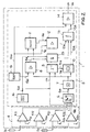
- Figure 1 shows an airbag control unit for motor vehicles with the functional blocks Evaluation unit 1, power unit 2 and a diagnostic computer 3.
- the acceleration signals supplied by two acceleration sensors S1 and S2 are fed to the evaluation unit 1 for evaluation uses these sensor signals to infer the vehicle condition. If those Acceleration signals on impending collision of the vehicle indicate, are firing commands to the power unit via a line 1a 2 passed.
- This power section generates when Ignition commands Ignition signals for the release means of airbags 2b, belt tensioners 2a and buckle switch 2c.
- the diagnostic computer 3 monitors and checks the functionality of the entire system.
- sensors S1 and S2 are offset from one another by 90 ° and arranged in each case 45 ° against the direction of travel P in the vehicle F, so that the sensor signals also provide direction information regarding the direction of impact deliver.
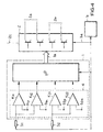
- FIG. 1 A hardware implementation of the evaluation unit 1 according to FIG. 1 is shown in Figure 2 and consists of a quantification unit 4 and an evaluation circuit 5.
- the acceleration signal from sensor S1 is fed to two comparators K11 and K12 and the sensor signals from sensor S2 are each fed to two further comparators K21 and K22.
- a positive and negative threshold s1n, s1p or s2n, s2p serve as thresholds for quantification: Sensor S1: s1p and s1n with s1p> s1n, Sensor S2: s2p and s2n with s2p> s2n.
- the output of the quantification unit 4 thus has 4 lines 4a to the input of a buffer 6 designed with D flip-flops be placed.
- This addition represents an evaluation function that is applied to the quantified sensor signals in order to generate a sensor signal identification value, ie the sum, with each time cycle.
- the truth table of such an evaluation function for the two sensors S1 and S2 is to be shown by way of example below, the sensitivity axes of which are arranged according to FIG. 3.
- Sensor S1 can thus be referred to as the left sensor and sensor S2 as the right sensor when viewed in the direction of travel.
- the evaluation function so defined that the directional information contained in the sensor signals essentially get lost. So they are with one from the left received front or right front collision of the vehicle sensor signals rated with (+1) (see lines 2 and 4), while with a corresponding collision from the left rear or right rear the rating is (-1) (see lines 3 and 7).
- vectors V output by the adder 7 are fed via line 7a to a comparator 8, a register 9 and a functional unit 10, which forms the difference and its amount from the vector V currently supplied and a vector V 0 generated in the previous time cycle.
- This vector V 0 is stored in the register 9 and is supplied to the functional unit 10 via the line 9a at the clock rate.
- the operation performed in the functional unit 10 corresponds to one Differentiation with subsequent calculation of the sum of the quantified sensor values, which is the amount of slope of successive Sum values on line 10a, which lead to an integrator 13 leads, queue.
- this integrator 13 are formed in successive time cycles Summed up slope values and forms a crash signal P, which in a comparator 14 connected downstream with a trigger threshold K2 becomes.
- this trigger threshold K2 is reached by the crash signal P. the safety devices are triggered.
- this integrator 13 should always be reset if there is no tripping over a certain period of time.
- the count value generated by the counter 11 is compared with a time constant T R provided by a register RAM 15 by means of the comparator 12. If the count value supplied to the comparator 12 via a line 11a exceeds this time constant T R , a reset pulse is fed to the integrator via a line 12a.
- the reset input of counter 11 is connected to the output of comparator 8 connected, its output signals also via a line 8a AND gate 25 supplies, which also receives the clock signal clk.
- the Clock signal clk is only released for integrator 13 if an output signal of the comparator 8 is present.
- An output signal is generated by the comparator 8 when one of the adder 7 generated vector exceeds a count threshold K1.
- This Counting threshold K1 is provided by the register RAM 15 via a line 10a.
- the comparator 8 only generates an output signal for the vectors (0, 0, 1) and (0, 1, 0), that is only when a collision from the left or right in the front or in the direction of travel from the front is expected.
- the counter 11 is set to "0" and likewise causes the integrator 13 to be reset if the crash signal P generated by the integrator 13 does not reach the triggering threshold K2 within the time constant T R.
- This trigger threshold K2 is also stored in the register RAM 15.
- the two constants K1 and T R must be matched to one another and are determined on the basis of crash data available for each vehicle type. These constants must be selected so that tripping must take place when this is required or no false tripping may occur.
- the method carried out with the circuit arrangement according to FIG. 2 fulfills these conditions with appropriately selected constants K1 and T R , ie classifies all crashes to 100%, the ignition delay times also being within an acceptable range. Since the triggering time of the safety devices must take place within a certain time period after the detection of a dangerous crash by the sensors, the ignition delay time indicates the time period that extends beyond this specific time period.
- the evaluation unit 1 thus exists 4 from a quantification unit 4 and a microprocessor uP.
- the other functional units correspond to those from FIG. 1.
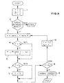
- a software implementation provided for such a microprocessor ⁇ P is shown in the program flow chart according to FIG. 5.
- the program variables P, V 0 and T are initialized in step 1.
- P represents the value of the integrated values of the amounts of the slopes
- V 0 is the vector belonging to a vector V from a preceding time cycle
- T indicates the time cycle.
- step 4 the sum of the quantified sensor signals sensL and sensR is formed as vector V. Then in step 4, this vector V is compared with the counting threshold K1, the meaning of which was explained in connection with FIG. 2. If the vector V exceeds this constant K1, the absolute value of the difference from this vector V is formed with the vector V 0 formed in the previous time cycle and integrated according to the formula given, ie added to the preceding integrator value P. At the same time, the clock pulse T is also set to "0". In the other case, this step 5 is skipped and the timing in step 6 is compared with the time constant T R , the meaning of which has also already been explained in connection with FIG. 2. If the tent cycle T reaches this threshold, the integrator value P is then reset in step 7. Otherwise step 7 is skipped.
- the integrator value P is compared in step 8 with a triggering threshold K2 and the safety devices in the vehicle are triggered if necessary (cf. step 9). If the trigger threshold K2 has not yet been reached, the clock cycle T is set to T + 1 and the current vector V becomes the vector V 0 (cf. step 10) in order to then start again with step 3.
- FIGS. 2 and 5 The method according to the invention explained with reference to FIGS. 2 and 5 is very simple and reliable with regard to the classification behavior.
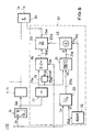
- a hardware implementation Such an assessment is shown in FIG. 6, with only a section there the circuit arrangement of Figure 2 is shown.
- FIG. 6 is a parameter matrix instead of the adder 7 known from FIG as a RAM matrix 71 between the buffer memory 6 and the functional unit 10 switched, whose functions explained in connection with Figure 2 were.
- the figures each show an associated evaluation matrix 7a and 7b.
- the quantified sensor values 0, 1 and -1 provide the information "no acceleration", positive acceleration "or” negative Acceleration ".
- the gi values are thus at the output of the RAM matrix 71 as 3-bit vectors V, which are in the same way as the vectors V be further processed according to FIG. It has been shown that a Accuracy of 3 bits of a gi value is sufficient so that each one Value can be between -3 and 3.
- the optimal allocation of the RAM matrix 71 depends on the respective vehicle signature and must be on the respective one Vehicle can be tuned using crash data.
- a further improvement in the time behavior of the method according to the invention is achieved with the evaluation matrix according to FIG. 7b, where the quantification the sensor signals do not have a positive and negative threshold Sn and Sp takes place, but where both switching thresholds are positive and with a high and low threshold is quantified, i.e. a strong or weak acceleration is detectable.
- a software implementation is also possible with such an evaluation matrix possible as an evaluation function and corresponds essentially 5 with the difference that the Vector not formed as an addition from the quantified sensor values is, but can be seen from the evaluation matrix.
- FIG. 8 shows the circuit arrangement according to FIG. 2 only partially, the functional unit realizing the evaluation function either can be designed as adding stage 7 or as evaluation matrix 71. at this additional evaluation becomes a dynamically shiftable one Trigger threshold Z generates that exponentially with the specified time grid increases. Since the threshold is small at the beginning, this means that this Procedure can only trigger at the beginning of a collision. So be if there is a serious accident, the safety devices immediately triggered.
- the buffered, quantified sensor values are stored in the Line 6a is first fed to a comparator 17, which is used to check is whether the quantified sensor values available in each time cycle of the Sensors S1 and S2 are positive (i.e. an impact direction opposite the Show driving direction of the vehicle). If this is the case, a line is used 17a a start pulse of both a counter 18 and a functional unit 21 fed, which operated either as a shift register or as a counter can be. At the same time, such a signal becomes a NAND gate 19 supplied with a corresponding input signal via a line 19a supplies a reset signal to the counter 18.
- the counter reading Z of this counter 18 now serves as a crash signal and is over a line 18a is fed to a further comparator 23, which is a comparison with the dynamic trigger threshold (R + K3). Will this Triggering threshold (R + K3) exceeded by the crash signal Z, there is a Activation of the release devices of the safety devices.
- This displaceable trigger threshold (R + K3) is in an adder stage 22 generated by a start value K3, which is via a line 15c of a RAM register 15 is entered, a count that increases with the timing R, which comes from the functional unit 21 via a line 21a, is added becomes.
- the counting down takes place bit by bit and therefore much more slowly. As a result, a certain amount of time must pass before the procedure (ie switching to the "shift register” function) again can be activated.
- the program flow chart shown in FIG. 9 represents the software implementation this extended evaluation process with a microprocessor After starting the program, the counter function Z, the divider function n and the register content R are set to "0". In step 2 the start value K3 is set, its meaning in connection with FIG. 8 was explained.
- step 3 If the safety devices are ready for operation (cf. step 3), it is then checked in a step 4 whether one of the sensor signals S1 or S2 is "0" and the most significant bit position bit H is occupied. If this is the case, the operating mode "shift register” is activated according to step 5. In the other case, this step 5 is skipped.
- step 6 If, according to step 6, both sensor signals S1 and S2 are positive, the next step is the counter function Z increased by "1". If this is not the case, the Counter set to "0" and only carried out step 9. The increase in Divider n to n + 1 is carried out until an upper limit is reached is (step 12). When this barrier B is reached, a sliding operation takes place at register R and resetting divider n to "0" (Step 13).
- step 10 it is checked whether a register content is in the operating mode "down counter" (R> 0) is present. If this is the case, the register content R reduced by "1", otherwise this step 11 is skipped.
- step 12 if the operating mode "shift register” according to step 12 is present and the counter n has reached a threshold B, the divider n is set to “0" and the register content R is increased by “1” and at the same time a "1" is added (cf. step 13).
- step 12 the operating mode "shift register” (see step 12) is not available or if n ⁇ B, then the sum of register contents R and Start value K3 formed, which now represents the trigger threshold, and with the Counter reading Z compared. If this trigger threshold is exceeded, it takes place a triggering of the safety devices (see step 17), otherwise it takes place a return to step 3.
- the mode of operation of this evaluation method is shown in the diagram in FIG shown.
- the curves S1 and S2 give the course of the acceleration signals sensors S1 and S2 during a collision on. At the beginning of the collision, both sensor signals show at the same time positive values, so that the crash signal Z increases linearly and at the same time the trigger threshold (R + K3) is generated. At the intersection of these two Curves Z and (R + K3) trigger the safety devices.
- This additional evaluation method can advantageously be carried out with the exemplary embodiments described at the outset are so matched that in addition to a 100% crash classification, very good temporal behavior, d. H. very quick ignition is achieved in the event of a crash.
Landscapes
- Engineering & Computer Science (AREA)
- Mechanical Engineering (AREA)
- Physics & Mathematics (AREA)
- General Physics & Mathematics (AREA)
- Air Bags (AREA)
- Automotive Seat Belt Assembly (AREA)
Claims (13)
- Procédé de déclenchement d'un dispositif de sécurité passif dans un véhicule pour des passagers, selon lequel au moyen de capteurs électriques (S1, S2), qui détectent un état critique du véhicule, d'un circuit d'évaluation (1) et de moyens de déclenchement pour le dispositif de sécurité, une activation des moyens de déclenchement de ce dispositif est exécutée en fonction des signaux d'accélération délivrés par les capteurs (S1, S2), auquel cas lors d'une première étape du procédé, les signaux des capteurs sont quantifiés, caractérisé par d'autres étapes du procédé indiquées ci-après:a) production de valeurs (vecteurs V, Vo) d'identification des signaux des capteurs à partir des signaux quantifiés des capteurs à l'aide d'une fonction de pondération,b) formation de la différence des valeurs (vecteurs V, Vo) d'identification des signaux des capteurs,c) formation des valeurs absolues des différences (V-Vo) des valeurs caractéristiques de signaux des capteurs,d) intégration des valeurs absolues (abs (V-Vo)) des différences (V-Vo) des valeurs caractéristiques des signaux des capteurs, ete) comparaison des valeurs d'intégration (P) à un seuil de déclenchement (K2).
- Procédé selon la revendication 1, caractérisé en ce qu'une addition des signaux quantifiés des capteurs est identifiée en tant que fonction de pondération et que la somme de cette addition représente la valeur caractéristique (vecteur V, Vo) du signal.
- Procédé selon la revendication 1, caractérisé en ce qu'il est prévu comme fonction de pondération une matrice de pondération (71) de telle sorte qu'une valeur caractéristique de signal (Vi, i = 1, ..., 8) tirée de la matrice de pondération (71) est associée aux valeurs quantifiées des capteurs.
- Procédé selon l'une des revendications précédentes, caractérisé en ce que deux seuils (s1p, s1n, s2p, s2n) sont utilisés pour chaque capteur (S1, S2) pour la quantification.
- Procédé selon la revendication 4, caractérisé en ce qu'on utilise un seuil positif et un seuil négatif (s1p, s1n, s2p, s2n) pour chaque capteur (S1, S2).
- Procédé selon la revendication 4, caractérisé en ce qu'on utilise deux seuils positifs (s1p, s2p).
- Procédé selon l'une des revendications 1 à 6, caractérisé en ce que les valeurs quantifiées des capteurs sont soumises en outre à un contrôle d'identité concernant la présence de signaux de capteurs indiquant simultanément une accélération positive, qu'en cas d'identité de signaux de capteurs se succédant dans le temps, un signal de crash augmentant linéairement est produit, qu'en fonction des valeurs caractéristiques de signaux des capteurs, qui sont produites par le contrôle d'identité, un seuil de déclenchement montant est produit et qu'enfin une activation des moyens de déclenchement est exécutée lorsque la valeur du signal de crash atteint le seuil de déclenchement.
- Procédé selon la revendication 7, caractérisé en ce que le seuil de déclenchement prend une valeur exponentielle.
- Dispositif pour la mise en oeuvre du procédé selon l'une des revendications précédentes, qui comprend des comparateurs (K1, ..., K4) pour quantifier les signaux des capteurs, caractérisé par d'autres caractéristiques indiquées ci-après:a) des moyens (7, 71, µP) sont prévus pour produire les valeurs (vecteurs V, Vo) de caractérisation de signaux de capteurs,b) d'autre part des moyens (9, 10) sont prévus pour former la différence des valeurs caractéristiques (vecteurs V, Vo) de signaux et pour la formation de la valeur absolue de la différence des valeurs caractéristiques (V-Vo) de signaux,c) il est en outre prévu un intégrateur (13) pour intégrer les valeurs absolues (abs (V-Vo)) des différences des valeurs caractéristiques (V-Vo) des signaux, etd) enfin un comparateur (14) sert à comparer les valeurs d'intégration (P) au seuil de déclenchement (K2).
- Dispositif selon la revendication 9, caractérisé en ce que les signaux quantifiés des capteurs sont mémorisés temporairement au moyen de bascules bistables de type D (6).
- Dispositif selon l'une des revendications 9 ou 10, caractérisé en ce qu'il est prévu deux capteurs d'accélération (S1, S2), dont les axes de sensibilité sont orientés en faisant un angle de + 45° et - 45° par rapport à l'axe longitudinal du véhicule (F) dans la direction de déplacement.
- Dispositif selon l'une des revendications 9 à 11, caractérisé en ce que le contrôle d'identité est exécuté au moyen d'un comparateur (17), en aval duquel un compteur (18) est branché pour l'obtention du signal de crash.
- Dispositif selon la revendication 12, caractérisé en ce que pour réaliser le seuil de déclenchement, il est prévu un générateur de cadence (20), un registre à décalage (21) utilisé comme compteur et un étage additionneur (22) branché en aval du registre à décalage, le registre à décalage (21) étant branché en aval du comparateur (17), et l'étage additionneur (22) ajoutant le contenu du registre à décalage (21) à une valeur de démarrage (K3) pour l'obtention du seuil de déclenchement (K3+R).
Applications Claiming Priority (2)
| Application Number | Priority Date | Filing Date | Title |
|---|---|---|---|
| DE19619414 | 1996-05-14 | ||
| DE19619414A DE19619414C1 (de) | 1996-05-14 | 1996-05-14 | Auslöseverfahren für passive Sicherheitseinrichtungen in Fahrzeugen |
Publications (2)
| Publication Number | Publication Date |
|---|---|
| EP0807558A1 EP0807558A1 (fr) | 1997-11-19 |
| EP0807558B1 true EP0807558B1 (fr) | 2002-07-17 |
Family
ID=7794287
Family Applications (1)
| Application Number | Title | Priority Date | Filing Date |
|---|---|---|---|
| EP97107333A Expired - Lifetime EP0807558B1 (fr) | 1996-05-14 | 1997-05-03 | Procédé de déclenchement d'un système de sécurité passif dans un véhicule |
Country Status (4)
| Country | Link |
|---|---|
| US (1) | US5892435A (fr) |
| EP (1) | EP0807558B1 (fr) |
| DE (2) | DE19619414C1 (fr) |
| ES (1) | ES2179242T3 (fr) |
Families Citing this family (25)
| Publication number | Priority date | Publication date | Assignee | Title |
|---|---|---|---|---|
| DE19632836C1 (de) * | 1996-08-14 | 1997-11-20 | Siemens Ag | Anordnung zum Auslösen von Rückhaltemitteln in einem Kraftfahrzeug |
| DE19645079A1 (de) * | 1996-10-31 | 1998-05-07 | Siemens Ag | Steueranordnung für ein Insassenschutzsystem zum Seitenaufprallschutz in einem Fahrzeug |
| JP3075209B2 (ja) * | 1997-04-01 | 2000-08-14 | トヨタ自動車株式会社 | 助手席用エアバッグ制御システム |
| DE19736840B4 (de) * | 1997-08-23 | 2006-01-26 | Volkswagen Ag | Verfahren zur situationsabhängigen Auslösung eines Rückhaltesystems und Rückhaltesystem |
| JP3910293B2 (ja) * | 1998-03-12 | 2007-04-25 | カルソニックカンセイ株式会社 | サイドエアバッグユニット |
| JPH11263187A (ja) * | 1998-03-19 | 1999-09-28 | Asuko Kk | 乗員保護装置の起動制御方法及び乗員保護装置の起動制御装置並びに乗員保護装置の起動制御プログラムを記録した記録媒体 |
| DE19816989B4 (de) * | 1998-04-17 | 2004-06-17 | Daimlerchrysler Ag | Verfahren zur Auslösung eines zweistufigen Airbag-Gasgenerators |
| DE19852468A1 (de) * | 1998-11-13 | 2000-05-25 | Siemens Ag | Steueranordnung für ein Insassenschutzmittel eines Fahrzeugs |
| DE19955551A1 (de) * | 1998-11-19 | 2000-05-25 | Inova Gmbh Tech Entwicklungen | Airbagvorrichtung und Auslöseverfahren dafür |
| JP2000255373A (ja) * | 1999-03-02 | 2000-09-19 | Mitsubishi Electric Corp | 車両衝突検出装置 |
| DE19937151B4 (de) * | 1999-08-06 | 2006-11-02 | Daimlerchrysler Ag | Aktives Insassenrückhaltesystem mit ring- und/oder stichförmiger Zündbusleitung |
| US6357790B1 (en) | 2000-01-20 | 2002-03-19 | Trw Inc. | Apparatus for use with child a child seat in a vehicle having a seat belt webbing pretensioner |
| WO2001094158A1 (fr) * | 2000-06-05 | 2001-12-13 | Siemens Aktiengesellschaft | Dispositif permettant de commander un element actif appartenant a un systeme de retenue des occupants d'un vehicule |
| JP3793504B2 (ja) * | 2000-08-22 | 2006-07-05 | シーメンス アクチエンゲゼルシヤフト | 自動車の乗員保護手段に対する制御回路および対応する作動方法 |
| DE10050956A1 (de) * | 2000-10-13 | 2002-05-02 | Bayerische Motoren Werke Ag | Verfahren zur Auslösung von wenigstens einem Rückhaltemittel |
| DE10311524A1 (de) * | 2003-03-17 | 2004-09-30 | Robert Bosch Gmbh | Verfahren zur Auslösung von Rückhaltemitteln |
| ATE370033T1 (de) * | 2005-01-25 | 2007-09-15 | Delphi Tech Inc | Verfahren zum beurteilen einer bewegung eines kraftfahrzeugs |
| DE102007029764A1 (de) * | 2006-06-27 | 2008-01-03 | Conti Temic Microelectronic Gmbh | Vorrichtung und Verfahren zur Sensierung einer gerichteten physikalischen Größe |
| CN101535092B (zh) * | 2006-11-14 | 2012-05-23 | 三菱电机株式会社 | 乘客保护装置的启动装置 |
| DE102007003542A1 (de) * | 2007-01-24 | 2008-07-31 | Robert Bosch Gmbh | Steuergerät und Verfahren zur Ansteuerung von einem Personenschutzsystem |
| DE102008045586B4 (de) | 2008-09-03 | 2017-09-14 | Audi Ag | Kollisions-und/oder Personenschutzsystem für ein Kraftfahrzeug und Verfahren dazu |
| DE102011010230B4 (de) * | 2011-02-03 | 2021-05-20 | Audi Ag | Verfahren und Vorrichtung zur Steuerung der Stromversorgung in einem Stromnetz eines Kraftwagens, sowie Kraftwagen |
| JP5952421B2 (ja) * | 2012-10-24 | 2016-07-13 | オートリブ ディベロップメント エービー | 乗員保護装置の制御装置 |
| CN103723105B (zh) * | 2013-12-23 | 2016-09-07 | 汪家琳 | 全能全自动总线车辆保安器 |
| US11648900B2 (en) * | 2020-07-27 | 2023-05-16 | Robert Bosch Gmbh | Off-zone crash detection using lateral accelerations at different positions in a vehicle |
Family Cites Families (22)
| Publication number | Priority date | Publication date | Assignee | Title |
|---|---|---|---|---|
| US3762495A (en) * | 1970-07-04 | 1973-10-02 | Nissan Motor | Method and device for triggering motor vehicle safety mechanisms |
| DE3001780C2 (de) * | 1980-01-18 | 1984-09-27 | Becker Autoradiowerk Gmbh, 7516 Karlsbad | Steueranordnung für Sicherheitseinrichtungen in Fahrzeugen |
| DE3717427C3 (de) * | 1987-05-23 | 1994-09-01 | Deutsche Aerospace | Aufprallsensor für Kraftfahrzeuge |
| DE3733837A1 (de) * | 1987-10-07 | 1989-04-27 | Messerschmitt Boelkow Blohm | Schaltungsanordnung zum erfassen von beschleunigungen |
| DE3816587A1 (de) * | 1988-05-16 | 1989-11-23 | Messerschmitt Boelkow Blohm | Einrichtung zur ausloesung einer passiven sicherheitseinrichtung |
| DE3816588A1 (de) * | 1988-05-16 | 1989-11-23 | Messerschmitt Boelkow Blohm | Einrichtung zur ausloesung einer passiven sicherheitseinrichtung |
| DE3924507A1 (de) * | 1989-02-18 | 1990-08-23 | Bosch Gmbh Robert | Verfahren zur ausloesung von rueckhaltemitteln |
| DE3920091A1 (de) * | 1989-04-06 | 1990-10-11 | Bosch Gmbh Robert | Sicherheitseinrichtung fuer fahrzeuginsassen |
| US5021678A (en) * | 1989-11-03 | 1991-06-04 | Trw Technar Inc. | Apparatus and method for actuating a passenger restraint system in a passenger vehicle |
| JP2543839B2 (ja) * | 1990-01-29 | 1996-10-16 | センサー・テクノロジー株式会社 | 衝突センサ |
| JP2905240B2 (ja) * | 1990-02-07 | 1999-06-14 | アスコ株式会社 | 車両安全装置のための制御システム |
| JPH05238348A (ja) * | 1991-03-13 | 1993-09-17 | Zexel Corp | 車両安全装置の制御システム |
| US5309138A (en) * | 1991-03-19 | 1994-05-03 | Honda Giken Kogyo Kabushiki Kaisha | Vehicle collision detecting method employing an acceleration sensor |
| DE4116336C1 (en) * | 1991-05-18 | 1992-06-11 | Messerschmitt-Boelkow-Blohm Gmbh, 8012 Ottobrunn, De | Passive safety device release assembly for motor vehicle occupant - has acceleration pick=ups with sensitivity axes directed to detect angle of frontal impact and supplying evaluating circuit |
| DE4117811A1 (de) * | 1991-05-31 | 1992-12-03 | Messerschmitt Boelkow Blohm | Verfahren zur aufprallerkennung bei fahrzeugen |
| JP2580405B2 (ja) * | 1991-06-04 | 1997-02-12 | 株式会社デンソー | 車両用乗員保護装置の起動装置 |
| DE69205067T2 (de) * | 1991-06-07 | 1996-03-21 | Kansei Kk | Aufprall-Schutzvorrichtung für Passagiere in einem Kraftfahrzeug oder dergleichen. |
| DE59205908D1 (de) * | 1991-10-31 | 1996-05-09 | I M M B Pineroli | Vorrichtung zum ermitteln von fahrzustandsgrössen eines kraftfahrzeuges |
| JP2954448B2 (ja) * | 1993-04-20 | 1999-09-27 | 三菱電機エンジニアリング株式会社 | 乗員保護装置の起動装置 |
| DE4330486C2 (de) * | 1993-09-09 | 1996-02-01 | Daimler Benz Ag | Verfahren zur Auslösung eines Airbags in einem Kraftfahrzeug |
| DE4424551A1 (de) * | 1994-07-12 | 1996-01-18 | Autoliv Dev | Auslösevorrichtung für ein Fahrzeug-Sicherheitssystem mit einem Beschleunigungssensor |
| DE19537546B4 (de) * | 1995-10-09 | 2004-12-02 | Conti Temic Microelectronic Gmbh | Aufprallerkennungsvorrichtung, insbesondere für ein Sicherheitssystem für Fahrzeuge zur Personenbeförderung |
-
1996
- 1996-05-14 DE DE19619414A patent/DE19619414C1/de not_active Expired - Fee Related
-
1997
- 1997-05-03 ES ES97107333T patent/ES2179242T3/es not_active Expired - Lifetime
- 1997-05-03 DE DE59707711T patent/DE59707711D1/de not_active Expired - Lifetime
- 1997-05-03 EP EP97107333A patent/EP0807558B1/fr not_active Expired - Lifetime
- 1997-05-13 US US08/855,568 patent/US5892435A/en not_active Expired - Lifetime
Also Published As
| Publication number | Publication date |
|---|---|
| DE19619414C1 (de) | 1997-08-21 |
| DE59707711D1 (de) | 2002-08-22 |
| EP0807558A1 (fr) | 1997-11-19 |
| ES2179242T3 (es) | 2003-01-16 |
| US5892435A (en) | 1999-04-06 |
Similar Documents
| Publication | Publication Date | Title |
|---|---|---|
| EP0807558B1 (fr) | Procédé de déclenchement d'un système de sécurité passif dans un véhicule | |
| EP0810129B1 (fr) | Procédé de déclenchement d'un système de sécurité passif dans un véhicule | |
| EP0342401B1 (fr) | Dispositif pour déclencher un système de sécurité passif | |
| EP0464033B1 (fr) | Appareil de commande de systemes de retenue de passagers et/ou de securite pour vehicules | |
| EP2318238B1 (fr) | Procédé et appareil de commande destinés à commander des moyens de protection des personnes pour un véhicule | |
| EP2509828B1 (fr) | Procédé et boîtier de commande pour la détermination du type d'une collision d'un véhicule | |
| DE4030612C2 (de) | Gassack-Auslösesteuersystem für ein Kraftfahrzeug | |
| DE4116336C1 (en) | Passive safety device release assembly for motor vehicle occupant - has acceleration pick=ups with sensitivity axes directed to detect angle of frontal impact and supplying evaluating circuit | |
| DE4117811C2 (fr) | ||
| EP0830271B1 (fr) | Dispositif de commande pour declencher un dispositif de retenue sur un vehicule en cas de choc lateral | |
| DE3879512T2 (de) | Vorrichtung und verfahren zur ausloesung eines sicherheitssystems zum schutz von kraftfahrzeuginsassen. | |
| DE4425845A1 (de) | Datenübertragungsverfahren in einem für den Einsatz in Kraftfahrzeugen geeigneten Datenverarbeitungssystem | |
| DE19623520B4 (de) | Auslösevorrichtung für eine Sicherheitsvorrichtung | |
| DE19537546B4 (de) | Aufprallerkennungsvorrichtung, insbesondere für ein Sicherheitssystem für Fahrzeuge zur Personenbeförderung | |
| DE10157203B4 (de) | Passives Sicherheitssystem | |
| DE10305087B4 (de) | Verfahren und Vorrichtung zum Steuern eines Insassenschutzmittels in einem Fahrzeug | |
| EP1140564B1 (fr) | Systeme de commande pour moyens de protection pour passagers d'une automobile | |
| DE3606567A1 (de) | Pruefverfahren fuer airbag-system-ausloeseschaltungen | |
| DE3816589C2 (fr) | ||
| DE10161004B4 (de) | Vorrichtung und Verfahren zur Bestimmung eines Aufpralls eines Fahrzeuges | |
| EP1955911B1 (fr) | Dispositif et procédé destinés à la commande de moyens de protection d'occupants | |
| DE3816591A1 (de) | Einrichtung zur ausloesung einer passiven sicherheitseinrichtung | |
| DE19900327A1 (de) | Verfahren zum Steuern der Auslösung mindestens einer Zündpille eines Insassenschutzsystems eines Kraftfahrzeugs, und entsprechend ausgelegtes Inassenschutzsystem | |
| EP1409298B2 (fr) | Dispositif et procede pour declencher un moyen de protection d'occupant d'un vehicule automobile | |
| DE102018214674A1 (de) | Verfahren und Vorrichtung zur Unfallfrüherkennung |
Legal Events
| Date | Code | Title | Description |
|---|---|---|---|
| PUAI | Public reference made under article 153(3) epc to a published international application that has entered the european phase |
Free format text: ORIGINAL CODE: 0009012 |
|
| AK | Designated contracting states |
Kind code of ref document: A1 Designated state(s): DE ES FR GB IT SE |
|
| 17P | Request for examination filed |
Effective date: 19971002 |
|
| RAP1 | Party data changed (applicant data changed or rights of an application transferred) |
Owner name: TEMIC SEMICONDUCTOR GMBH |
|
| RAP1 | Party data changed (applicant data changed or rights of an application transferred) |
Owner name: ATMEL GERMANY GMBH |
|
| 17Q | First examination report despatched |
Effective date: 20001128 |
|
| GRAG | Despatch of communication of intention to grant |
Free format text: ORIGINAL CODE: EPIDOS AGRA |
|
| GRAG | Despatch of communication of intention to grant |
Free format text: ORIGINAL CODE: EPIDOS AGRA |
|
| GRAH | Despatch of communication of intention to grant a patent |
Free format text: ORIGINAL CODE: EPIDOS IGRA |
|
| GRAH | Despatch of communication of intention to grant a patent |
Free format text: ORIGINAL CODE: EPIDOS IGRA |
|
| GRAA | (expected) grant |
Free format text: ORIGINAL CODE: 0009210 |
|
| AK | Designated contracting states |
Kind code of ref document: B1 Designated state(s): DE ES FR GB IT SE |
|
| REG | Reference to a national code |
Ref country code: GB Ref legal event code: FG4D Free format text: NOT ENGLISH |
|
| GBT | Gb: translation of ep patent filed (gb section 77(6)(a)/1977) |
Effective date: 20020718 |
|
| REF | Corresponds to: |
Ref document number: 59707711 Country of ref document: DE Date of ref document: 20020822 |
|
| REG | Reference to a national code |
Ref country code: ES Ref legal event code: FG2A Ref document number: 2179242 Country of ref document: ES Kind code of ref document: T3 |
|
| ET | Fr: translation filed | ||
| PLBE | No opposition filed within time limit |
Free format text: ORIGINAL CODE: 0009261 |
|
| STAA | Information on the status of an ep patent application or granted ep patent |
Free format text: STATUS: NO OPPOSITION FILED WITHIN TIME LIMIT |
|
| 26N | No opposition filed |
Effective date: 20030422 |
|
| PGFP | Annual fee paid to national office [announced via postgrant information from national office to epo] |
Ref country code: SE Payment date: 20060512 Year of fee payment: 10 |
|
| PGFP | Annual fee paid to national office [announced via postgrant information from national office to epo] |
Ref country code: FR Payment date: 20060519 Year of fee payment: 10 |
|
| PGFP | Annual fee paid to national office [announced via postgrant information from national office to epo] |
Ref country code: GB Payment date: 20060522 Year of fee payment: 10 |
|
| PGFP | Annual fee paid to national office [announced via postgrant information from national office to epo] |
Ref country code: ES Payment date: 20060530 Year of fee payment: 10 |
|
| PGFP | Annual fee paid to national office [announced via postgrant information from national office to epo] |
Ref country code: IT Payment date: 20070514 Year of fee payment: 11 |
|
| EUG | Se: european patent has lapsed | ||
| GBPC | Gb: european patent ceased through non-payment of renewal fee |
Effective date: 20070503 |
|
| REG | Reference to a national code |
Ref country code: FR Ref legal event code: ST Effective date: 20080131 |
|
| PG25 | Lapsed in a contracting state [announced via postgrant information from national office to epo] |
Ref country code: GB Free format text: LAPSE BECAUSE OF NON-PAYMENT OF DUE FEES Effective date: 20070503 |
|
| PG25 | Lapsed in a contracting state [announced via postgrant information from national office to epo] |
Ref country code: SE Free format text: LAPSE BECAUSE OF NON-PAYMENT OF DUE FEES Effective date: 20070504 |
|
| PG25 | Lapsed in a contracting state [announced via postgrant information from national office to epo] |
Ref country code: FR Free format text: LAPSE BECAUSE OF NON-PAYMENT OF DUE FEES Effective date: 20070531 |
|
| REG | Reference to a national code |
Ref country code: ES Ref legal event code: FD2A Effective date: 20070504 |
|
| PG25 | Lapsed in a contracting state [announced via postgrant information from national office to epo] |
Ref country code: ES Free format text: LAPSE BECAUSE OF NON-PAYMENT OF DUE FEES Effective date: 20070504 |
|
| PG25 | Lapsed in a contracting state [announced via postgrant information from national office to epo] |
Ref country code: IT Free format text: LAPSE BECAUSE OF NON-PAYMENT OF DUE FEES Effective date: 20080503 |
|
| PGFP | Annual fee paid to national office [announced via postgrant information from national office to epo] |
Ref country code: DE Payment date: 20120529 Year of fee payment: 16 |
|
| REG | Reference to a national code |
Ref country code: DE Ref legal event code: R119 Ref document number: 59707711 Country of ref document: DE |
|
| PG25 | Lapsed in a contracting state [announced via postgrant information from national office to epo] |
Ref country code: DE Free format text: LAPSE BECAUSE OF NON-PAYMENT OF DUE FEES Effective date: 20131203 |
|
| REG | Reference to a national code |
Ref country code: DE Ref legal event code: R079 Ref document number: 59707711 Country of ref document: DE Free format text: PREVIOUS MAIN CLASS: B60R0021320000 Ipc: B60R0021010000 |
|
| REG | Reference to a national code |
Ref country code: DE Ref legal event code: R119 Ref document number: 59707711 Country of ref document: DE Effective date: 20131203 Ref country code: DE Ref legal event code: R079 Ref document number: 59707711 Country of ref document: DE Free format text: PREVIOUS MAIN CLASS: B60R0021320000 Ipc: B60R0021010000 Effective date: 20140530 |