EP0807547A1 - Light fixation using a zigzag folded spring on the vehicle body - Google Patents
Light fixation using a zigzag folded spring on the vehicle body Download PDFInfo
- Publication number
- EP0807547A1 EP0807547A1 EP97401052A EP97401052A EP0807547A1 EP 0807547 A1 EP0807547 A1 EP 0807547A1 EP 97401052 A EP97401052 A EP 97401052A EP 97401052 A EP97401052 A EP 97401052A EP 0807547 A1 EP0807547 A1 EP 0807547A1
- Authority
- EP
- European Patent Office
- Prior art keywords
- housing
- fixing
- spring
- hoop
- bodywork
- Prior art date
- Legal status (The legal status is an assumption and is not a legal conclusion. Google has not performed a legal analysis and makes no representation as to the accuracy of the status listed.)
- Granted
Links
Images


Classifications
-
- B—PERFORMING OPERATIONS; TRANSPORTING
- B60—VEHICLES IN GENERAL
- B60Q—ARRANGEMENT OF SIGNALLING OR LIGHTING DEVICES, THE MOUNTING OR SUPPORTING THEREOF OR CIRCUITS THEREFOR, FOR VEHICLES IN GENERAL
- B60Q1/00—Arrangement of optical signalling or lighting devices, the mounting or supporting thereof or circuits therefor
- B60Q1/02—Arrangement of optical signalling or lighting devices, the mounting or supporting thereof or circuits therefor the devices being primarily intended to illuminate the way ahead or to illuminate other areas of way or environments
- B60Q1/04—Arrangement of optical signalling or lighting devices, the mounting or supporting thereof or circuits therefor the devices being primarily intended to illuminate the way ahead or to illuminate other areas of way or environments the devices being headlights
- B60Q1/0408—Arrangement of optical signalling or lighting devices, the mounting or supporting thereof or circuits therefor the devices being primarily intended to illuminate the way ahead or to illuminate other areas of way or environments the devices being headlights built into the vehicle body, e.g. details concerning the mounting of the headlamps on the vehicle body
- B60Q1/0433—Arrangement of optical signalling or lighting devices, the mounting or supporting thereof or circuits therefor the devices being primarily intended to illuminate the way ahead or to illuminate other areas of way or environments the devices being headlights built into the vehicle body, e.g. details concerning the mounting of the headlamps on the vehicle body the housing being fastened onto the vehicle body using screws
-
- B—PERFORMING OPERATIONS; TRANSPORTING
- B60—VEHICLES IN GENERAL
- B60Q—ARRANGEMENT OF SIGNALLING OR LIGHTING DEVICES, THE MOUNTING OR SUPPORTING THEREOF OR CIRCUITS THEREFOR, FOR VEHICLES IN GENERAL
- B60Q1/00—Arrangement of optical signalling or lighting devices, the mounting or supporting thereof or circuits therefor
- B60Q1/02—Arrangement of optical signalling or lighting devices, the mounting or supporting thereof or circuits therefor the devices being primarily intended to illuminate the way ahead or to illuminate other areas of way or environments
- B60Q1/04—Arrangement of optical signalling or lighting devices, the mounting or supporting thereof or circuits therefor the devices being primarily intended to illuminate the way ahead or to illuminate other areas of way or environments the devices being headlights
- B60Q1/0408—Arrangement of optical signalling or lighting devices, the mounting or supporting thereof or circuits therefor the devices being primarily intended to illuminate the way ahead or to illuminate other areas of way or environments the devices being headlights built into the vehicle body, e.g. details concerning the mounting of the headlamps on the vehicle body
- B60Q1/045—Arrangement of optical signalling or lighting devices, the mounting or supporting thereof or circuits therefor the devices being primarily intended to illuminate the way ahead or to illuminate other areas of way or environments the devices being headlights built into the vehicle body, e.g. details concerning the mounting of the headlamps on the vehicle body with provision for adjusting the alignment of the headlamp housing with respect to the vehicle body
-
- B—PERFORMING OPERATIONS; TRANSPORTING
- B60—VEHICLES IN GENERAL
- B60Q—ARRANGEMENT OF SIGNALLING OR LIGHTING DEVICES, THE MOUNTING OR SUPPORTING THEREOF OR CIRCUITS THEREFOR, FOR VEHICLES IN GENERAL
- B60Q1/00—Arrangement of optical signalling or lighting devices, the mounting or supporting thereof or circuits therefor
- B60Q1/26—Arrangement of optical signalling or lighting devices, the mounting or supporting thereof or circuits therefor the devices being primarily intended to indicate the vehicle, or parts thereof, or to give signals, to other traffic
- B60Q1/2619—Arrangement of optical signalling or lighting devices, the mounting or supporting thereof or circuits therefor the devices being primarily intended to indicate the vehicle, or parts thereof, or to give signals, to other traffic built in the vehicle body
- B60Q1/2623—Details of the fastening means
- B60Q1/2626—Screw-nut fasteners
-
- B—PERFORMING OPERATIONS; TRANSPORTING
- B60—VEHICLES IN GENERAL
- B60Q—ARRANGEMENT OF SIGNALLING OR LIGHTING DEVICES, THE MOUNTING OR SUPPORTING THEREOF OR CIRCUITS THEREFOR, FOR VEHICLES IN GENERAL
- B60Q1/00—Arrangement of optical signalling or lighting devices, the mounting or supporting thereof or circuits therefor
- B60Q1/26—Arrangement of optical signalling or lighting devices, the mounting or supporting thereof or circuits therefor the devices being primarily intended to indicate the vehicle, or parts thereof, or to give signals, to other traffic
- B60Q1/2619—Arrangement of optical signalling or lighting devices, the mounting or supporting thereof or circuits therefor the devices being primarily intended to indicate the vehicle, or parts thereof, or to give signals, to other traffic built in the vehicle body
- B60Q1/2642—Arrangement of optical signalling or lighting devices, the mounting or supporting thereof or circuits therefor the devices being primarily intended to indicate the vehicle, or parts thereof, or to give signals, to other traffic built in the vehicle body with provision for adjusting the alignment of the device housing with respect to the vehicle body
Definitions
- the present invention relates to a fixing device for assembling a lighting and / or signaling device of a motor vehicle to the body of a motor vehicle, by making up for the play due in particular to manufacturing tolerances.
- FR-A-2 719 269 a fixing device which allows adjustment according to three dimensions of the relative position of a zone of attachment of a housing or base of the lighting device and / or signaling and bodywork of the motor vehicle.
- This known device mainly comprises two elements capable of sliding relative to each other, one element being secured to the housing or base, and the other fixed to the body by a screw, cooperating with a nut. Means allow the immobilization of the assembly in a blocking position.
- Such a fixing device allows adjustment of the position of the housing relative to the body in three independent directions. However, it does not always adapt to a wide variety of positioning defects, and in particular to a defect in the angular position of the surfaces of the housing and of the vehicle body. In addition, this device implements several independent parts, which must be combined to make the fixing, which complicates the assembly, and multiplies the risk of loss of parts and the various tightenings required when mounting the light on the bodywork.
- Another device proposed in document DE-C-195 11 137, makes it possible to fix a housing for a signaling or lighting device on the body of the vehicle and comprises two snap-on ends joined by a movable spring, guided in its direction d 'elongation.
- this known device does not offer freedom of positioning in the plane perpendicular to the direction of elongation and is ill-suited to all types of positioning faults.
- the object of the present invention is to propose a device for fixing a housing of a signaling or lighting device to the vehicle body, the ability of which to make up for play being improved.
- Another object of the invention is to propose a fixing device whose assembly is simpler and quicker.
- the present invention provides a device for fixing a housing of a lighting or signaling device of a motor vehicle on the body of the vehicle, comprising a body in one piece having an elastically deformable part in elongation separating a part of attachment to the body of a part for fixing to the housing, characterized in that one of the two fixing parts is capable of being engaged in an associated housing of the housing or of the body, so as to have in this housing two degrees of freedom transversely to the direction of elongation of the elastically deformable part.
- the device is characterized in that the body is made of plastic and comprises in said elastically deformable part a groove in which is embedded a metal spring with a sinuous leaf, said spring having at least one of its ends at least one hooking tooth with body material.
- the device is characterized in that the fixing part to the housing comprises a hollow head connected to the elastically deformable part by a narrower part, the latter being able to be engaged in an opening formed in a wall integral with the housing after latching through a through passage communicating laterally with said opening.
- the device is characterized in that the body comprises, at a distance from the head corresponding substantially to the thickness of said wall, a flange.
- the device is also characterized in that the part for fixing to the body has a non-removable threaded rod, capable of passing through the body and of cooperating with a nut, or alternatively, said part is capable of cooperating with a screw passing through the bodywork, or according to another variant, said part is capable of cooperating with a hoop having a locking groove at the end of external threading and capable of cooperating with a screw passing through the bodywork.
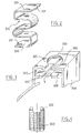
- FIG. 1 represents a fixing device intended to operate between a housing 350 integral with a housing 300 of a motor vehicle signaling light and an attachment zone 450 of the bodywork 400 of the vehicle.
- the fixing device consists mainly of a body 100, a sinuous spring 200, a screw 500 and a hoop 600.
- It has a main axis ZZ, along which the body 100 of the device comprises three parts.
- a part 110 located at one end of the body, makes it possible to connect the latter to the housing 300 while being engaged in the housing 350.
- a part 130, or base, located at the other end of the body, makes it possible to fix the body 100 to the attachment zone 450 of the bodywork.
- the central part 120 of the body is intended to accommodate a sinuous leaf spring 200.
- the part 110 of the body is generally cylindrical with an axis ZZ. It has a collar 111 seated on the part 120 of the body, and a hollow disc 113 situated at a certain distance from the collar, and parallel to the latter.
- the disc 113 is in this case of the same diameter as the collar.
- a portion 112 of smaller diameter connects the disc 113 to the flange 111.
- the connecting portion 112 and the disc 113 are hollowed out and can undergo a certain elastic deformation.
- the housing 350 of the housing which cooperates with the part 110 of the body 100, is shown in FIG. 3.
- This housing 350 is of parallelepiped shape. It has two flat faces 351 and 352 perpendicular to the axis ZZ, and located between two parallel sides 353 and 354 coming from the housing 300 of the light.
- the rear face 351 (above in the figure) of the housing has a circular opening 355 located in its center.
- the diameter of the opening 355 is less than the diameter of the collar 111 and the disc 113 of the body 100.
- a through passage 356 in the face 351 allows the axis 112 to be engaged in the opening 355, by elastic deformation or snap-fastening, allowing movement of the part 110 of the body 100 in the plane perpendicular to the axis ZZ, thanks to the fact that the transverse dimensions of the disc 113 are smaller than those of the housing 350 and the fact that the section of the axis 112 is smaller than the size of the opening 355.
- the fixing device can be positioned freely in the housing of the light housing, to adapt to different games in the transverse positioning of the housing relative to the body.
- the thickness of the head 113 is very slightly less than that of the housing 350, so as to stabilize the body 100 of the device inserted in the housing, in a position perpendicular to the surface of the housing 350 of the housing.
- the space between the flange 111 and the head 113 will be very slightly greater than the thickness of the rear face 351 of the housing and the body of the device will also be kept perpendicular to the surface of the housing 350 of the housing.
- the central part 120 of the body 100 has a sinuous shape, and has a hollow open space 121, or groove, making it possible to accommodate the spring 200.
- a tooth 201 makes it possible to retain the spring inside space 121.
- the body 100 is made of thermoplastic material.
- the body 100 is able to follow and adapt to the different elastic deformations of the spring 200.
- the sinuous leaf spring 200 is shown in Figure 2. It has four curved folds and two flat ends. On the free edge of each end, the spring has the aforementioned retaining tooth 201.
- the mounting and blocking of the spring 200 in the body 100 is carried out as follows.
- the spring is presented from the side, along the hollow shape of the part 120 of the body 100, then inserted by pressure into said part 120.
- the teeth 201 ensure its retention by hooking into the material of the body at the ends of its shape in hollow 121.
- the spring 200 is preferably made of steel.
- the fixing device is capable, thanks to the spring 200, of undergoing a wide variety of elongations along the ZZ axis and flexions, absorbing forces during assembly.
- Spring 200 can be replaced if necessary in the event of failure.
- the part 130 of the body 100 houses a hoop 600 and an O-ring seal 700.
- the part 130 of the body has a generally cylindrical tapped bore, of axis ZZ, in which the hoop 600 is received.
- a groove 132 In the end face of the part 130 is formed a groove 132, which receives the gasket. tightness 700.
- the hoop 600 is shown in FIG. 4.
- the outside diameter of the hoop corresponds to that of the bore of the part 130, and its internal bore is tapped to cooperate with the screw 500.
- the hoop 600 is threaded on its faces external and internal, and preferably has a locking groove 610 at the top of the external thread.
- the hoop remains in place, blocked by the blocking groove.
- the hoop is advantageously made of brass, and its object is to prevent the part 130 of the body, made of a plastic material, from splitting when the screw 500 is tightened.
- the attachment zone 450 shown in FIG. 1 receives the part 130 of the body of the device.
- the attachment zone 450 is flat, and has an ordinary circular opening 451, suitable for receiving the screw 500.
- the fixing device which has just been described is used in the following manner during the mounting or dismounting of the binding.
- the spring 200, the hoop 600 and the seal 700 are initially mounted on the body 100 of the device, as indicated above.
- the part 120 of the body is snapped into the housing 350 of the fire housing 300. Then the screw 500 is engaged in the opening 451 of the bodywork, and screwed into the hoop 600 of the body 100. Under the effect of the tightening of the screw 500, the part 120 of the body housing the spring 200 is deformed, and the 'base 130 of the body is applied against the attachment zone 450 of the body, thus holding the housing 300 in place.
- the fixing of the housing 300 to the body 400 requires only two independent parts, namely the screw 500 and the body 100 comprising the spring 200, the hoop 600 and the seal 700.
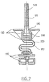
- the part 130 of the body of the fixing comprises a non-removable stud 510 of axis ZZ, opening out through the end face of the part 130, upwards in the figure 7.
- the stud 510 has a threaded rod 511 and an attachment zone 515 with the part 130 of the body.
- a head 516 makes it possible to immobilize the stud in the body 100, molded around the stud.
- the mounting of the signaling light on the vehicle body is carried out by screwing a nut on the threaded rod 511 of the device, inserted in the attachment zone 450 of the body.
- the body 100 of the device and the spring 200, as well as the hoop 600 in different materials, and to assemble them by different techniques.
- the body 100 can for example be molded onto the hoop 600 and / or the spring 200, which then constitute inserts.
Abstract
Description
La présente invention concerne un dispositif de fixation permettant d'assembler un dispositif d'éclairage et/ou de signalisation de véhicule automobile à la carrosserie d'un véhicule automobile, en rattrapant les jeux dus notamment aux tolérances de fabrication.The present invention relates to a fixing device for assembling a lighting and / or signaling device of a motor vehicle to the body of a motor vehicle, by making up for the play due in particular to manufacturing tolerances.
Pour des raisons d'ordre essentiellement esthétique, les constructeurs automobiles recherchent depuis quelques années un positionnement de plus en plus précis des feux de signalisation et des projecteurs, afin qu'ils s'intègrent parfaitement aux formes du véhicule et ne jouent pas dans leur logement.For essentially aesthetic reasons, car manufacturers have been looking for an increasingly precise positioning of traffic lights and searchlights for a few years, so that they fit perfectly into the shapes of the vehicle and do not play in their housing. .
La demanderesse a déjà proposé dans FR-A-2 719 269 un dispositif de fixation qui permet un réglage selon trois dimensions de la position relative d'une zone d'attache d'un boîtier ou socle du dispositif d'éclairage et/ou de signalisation et de la carrosserie du véhicule automobile.The Applicant has already proposed in FR-A-2 719 269 a fixing device which allows adjustment according to three dimensions of the relative position of a zone of attachment of a housing or base of the lighting device and / or signaling and bodywork of the motor vehicle.
Ce dispositif connu comprend principalement deux éléments capables de coulisser l'un par rapport à l'autre, un élément étant solidarisé au boîtier ou socle, et l'autre fixé sur la carrosserie par une vis, coopérant avec un écrou. Des moyens permettent l'immobilisation de l'ensemble dans une position de blocage.This known device mainly comprises two elements capable of sliding relative to each other, one element being secured to the housing or base, and the other fixed to the body by a screw, cooperating with a nut. Means allow the immobilization of the assembly in a blocking position.
Un tel dispositif de fixation permet un réglage de la position du boîtier par rapport à la carrosserie suivant trois directions indépendantes. Mais il ne s'adapte pas toujours à une grande variété de défauts de positionnement, et en particulier à un défaut de position angulaire des surfaces du boîtier et de la carrosserie du véhicule. De plus, ce dispositif met en oeuvre plusieurs pièces indépendantes, qu'il faut associer pour réaliser la fixation, ce qui complique le montage, et multiplie les risques de perte de pièces et les différents serrages nécessaires lors du montage du feu sur la carrosserie.Such a fixing device allows adjustment of the position of the housing relative to the body in three independent directions. However, it does not always adapt to a wide variety of positioning defects, and in particular to a defect in the angular position of the surfaces of the housing and of the vehicle body. In addition, this device implements several independent parts, which must be combined to make the fixing, which complicates the assembly, and multiplies the risk of loss of parts and the various tightenings required when mounting the light on the bodywork.
Un autre dispositif, proposé dans le document DE-C-195 11 137, permet de fixer un boîtier de dispositif de signalisation ou d'éclairage sur la carrosserie du véhicule et comprend deux extrémités encliquetables réunies par un ressort mobile, guidé dans sa direction d'élongation.Another device, proposed in document DE-C-195 11 137, makes it possible to fix a housing for a signaling or lighting device on the body of the vehicle and comprises two snap-on ends joined by a movable spring, guided in its direction d 'elongation.
Mais ce dispositif connu n'offre pas de liberté de positionnement dans le plan perpendiculaire à la direction d'élongation et s'adapte mal à tous types de défauts de positionnement.However, this known device does not offer freedom of positioning in the plane perpendicular to the direction of elongation and is ill-suited to all types of positioning faults.
Par ailleurs, on remarque que l'encliquetage de ce dispositif entre le boîtier et la carrosserie nécessite une pression sur le dispositif, dans le sens de la compression du ressort, et qu'un système de blocage du ressort lors du montage est donc prévu pour éviter que le ressort ne fléchisse. Ceci aboutit à une structure compliquée et encombrante, avec des risques de rupture du dispositif.Furthermore, it is noted that the snap-fastening of this device between the housing and the body requires pressure on the device, in the direction of the compression of the spring, and that a system for locking the spring during assembly is therefore provided for prevent the spring from bending. This results in a complicated and bulky structure, with risks of rupture of the device.
Le but de la présente invention est de proposer un dispositif de fixation d'un boîtier de dispositif de signalisation ou d'éclairage à la carrosserie du véhicule, dont l'aptitude à rattraper les jeux soit améliorée.The object of the present invention is to propose a device for fixing a housing of a signaling or lighting device to the vehicle body, the ability of which to make up for play being improved.
Un autre but de l'invention est de proposer un dispositif de fixation dont le montage soit plus simple et rapide.Another object of the invention is to propose a fixing device whose assembly is simpler and quicker.
La présente invention propose un dispositif de fixation d'un boîtier de dispositif d'éclairage ou de signalisation d'un véhicule automobile sur la carrosserie du véhicule, comprenant un corps d'un seul tenant possédant une partie élastiquement déformable en allongement séparant une partie de fixation à la carrosserie d'une partie de fixation au boîtier, caractérisé en ce que l'une des deux parties de fixation est apte à être engagée dans un logement associé du boîtier ou de la carrosserie, de manière à disposer dans ce logement de deux degrés de liberté transversalement à la direction d'allongement de la partie élastiquement déformable.The present invention provides a device for fixing a housing of a lighting or signaling device of a motor vehicle on the body of the vehicle, comprising a body in one piece having an elastically deformable part in elongation separating a part of attachment to the body of a part for fixing to the housing, characterized in that one of the two fixing parts is capable of being engaged in an associated housing of the housing or of the body, so as to have in this housing two degrees of freedom transversely to the direction of elongation of the elastically deformable part.
Par ailleurs, le dispositif est caractérisé en ce que le corps est réalisé en matière plastique et comporte dans ladite partie élastiquement déformable une gorge dans laquelle est encastré un ressort métallique à lame sinueux, ledit ressort possèdant à au moins une de ses extrémités au moins une dent d'accrochage avec la matière du corps.Furthermore, the device is characterized in that the body is made of plastic and comprises in said elastically deformable part a groove in which is embedded a metal spring with a sinuous leaf, said spring having at least one of its ends at least one hooking tooth with body material.
Plus particulièrement, le dispositif est caractérisé en ce que la partie de fixation au boîtier comporte une tête creuse reliée à la partie élastiquement déformable par une partie plus étroite, cette dernière étant apte à être engagée dans une ouverture formée dans une paroi solidaire du boîtier après encliquetage à travers un passage débouchant communiquant latéralement avec ladite ouverture.More particularly, the device is characterized in that the fixing part to the housing comprises a hollow head connected to the elastically deformable part by a narrower part, the latter being able to be engaged in an opening formed in a wall integral with the housing after latching through a through passage communicating laterally with said opening.
Egalement, le dispositif est caractérisé en ce que le corps comporte, à une distance de la tête correspondant sensiblement à l'épaisseur de ladite paroi, une collerette.Also, the device is characterized in that the body comprises, at a distance from the head corresponding substantially to the thickness of said wall, a flange.
Le dispositif est aussi caractérisé en ce que la partie de fixation à la carrosserie présente une tige filetée inamovible, apte à traverser la carrosserie et à coopérer avec un écrou, ou bien selon une variante, ladite partie est apte à coopérer avec une vis traversant la carrosserie, ou encore selon une autre variante, ladite partie est apte à coopérer avec une frette présentant une rainure de blocage en fin de filetage extérieur et apte à coopérer avec une vis traversant la carrosserie.The device is also characterized in that the part for fixing to the body has a non-removable threaded rod, capable of passing through the body and of cooperating with a nut, or alternatively, said part is capable of cooperating with a screw passing through the bodywork, or according to another variant, said part is capable of cooperating with a hoop having a locking groove at the end of external threading and capable of cooperating with a screw passing through the bodywork.
D'autres caractéristiques et avantages de l'invention apparaîtront à la lecture de la description qui suit. Cette description est purement illustrative et non limitative. Elle doit être lue en regard des dessins annexés sur lesquels :
- . la figure 1 est une vue de dessus et partiellement en coupe horizontale d'un dispositif de fixation monté entre un boîtier de feu de signalisation et la carrosserie du véhicule ;
- . la figure 2 est une vue en perspective d'un élément du dispositif de fixation ;
- . la figure 3 est une vue en perspective d'une partie du boîtier de feu coopérant avec le dispositif de fixation ;
- . la figure 4 est une vue en élévation d'un autre élément du dispositif de fixation ;
- . la figure 5 est une vue analogue à la figure 1, montrant le dispositif de fixation dans trois états possibles ;
- . la figure 6 est une vue de dessus et partiellement en coupe d'une variante du dispositif de fixation ;
- . la figure 7 est une vue en coupe de dessus d'une variante du dispositif de fixation.
- . Figure 1 is a top view and partially in horizontal section of a fixing device mounted between a signaling light housing and the vehicle body;
- . Figure 2 is a perspective view of an element of the fixing device;
- . Figure 3 is a perspective view of a portion of the light housing cooperating with the fixing device;
- . Figure 4 is an elevational view of another element of the fixing device;
- . Figure 5 is a view similar to Figure 1 showing the fixing device in three possible states;
- . Figure 6 is a top view and partially in section of a variant of the fixing device;
- . Figure 7 is a top sectional view of a variant of the fixing device.
La figure 1 représente un dispositif de fixation destiné à opérer entre un logement 350 solidaire d'un boîtier 300 d'un feu de signalisation de véhicule automobile et une zone d'attache 450 de la carrosserie 400 du véhicule.FIG. 1 represents a fixing device intended to operate between a
Le dispositif de fixation est constitué principalement d'un corps 100, d'un ressort sinueux 200, d'une vis 500 et d'une frette 600.The fixing device consists mainly of a
Il admet un axe principal ZZ, le long duquel le corps 100 du dispositif comprend trois parties.It has a main axis ZZ, along which the
Une partie 110, située à une extrémité du corps, permet de relier celui-ci au boîtier 300 en étant engagée dans le logement 350.A
Une partie 130, ou embase, située à l'autre extrémité du corps, permet de fixer le corps 100 à la zone d'attache 450 de la carrosserie.A
La partie centrale 120 du corps est destinée à loger un ressort en lame sinueux 200.The
La partie 110 du corps est généralement cylindrique d'axe ZZ. Elle présente une collerette 111 assise sur la partie 120 du corps, et un disque creux 113 situé à une certaine distance de la collerette, et parallèle à celle-ci.The
Le disque 113 est en l'espèce de même diamètre que la collerette. Une partie 112 de plus petit diamètre relie le disque 113 à la collerette 111. La partie de liaison 112 et le disque 113 sont évidés et peuvent subir une certaine déformation élastique.The
Le logement 350 du boîtier, qui coopère avec la partie 110 du corps 100, est représenté sur la figure 3.The
Ce logement 350 est de forme parallélépipédique. Il présente deux faces planes 351 et 352 perpendiculaires à l'axe ZZ, et situées entre deux flancs parallèles 353 et 354 issus du boîtier 300 du feu.This
La face postérieure 351 (en haut sur la figure) du logement présente une ouverture circulaire 355 située en son centre. Le diamètre de l'ouverture 355 est inférieur au diamètre de la collerette 111 et du disque 113 du corps 100. Un passage débouchant 356 dans la face 351 permet à l'axe 112 d'être engagé dans l'ouverture 355, par déformation élastique ou encliquetage, autorisant un déplacement de la partie 110 du corps 100 dans le plan perpendiculaire à l'axe ZZ, grâce au fait que les dimensions transversales du disque 113 sont inférieures à celles du logement 350 et du fait que la section de l'axe 112 est plus petite que la taille de l'ouverture 355.The rear face 351 (above in the figure) of the housing has a
Ainsi, selon une caractéristique de l'invention, le dispositif de fixation peut se positionner librement dans le logement du boîtier de feu, pour s'adapter à différents jeux dans le positionnement transversal du boîtier par rapport à la carrosserie.Thus, according to a characteristic of the invention, the fixing device can be positioned freely in the housing of the light housing, to adapt to different games in the transverse positioning of the housing relative to the body.
De préférence, l'épaisseur de la tête 113 est très légèrement inférieure à celle du logement 350, de façon à stabiliser le corps 100 du dispositif inséré dans le logement, dans une position perpendiculaire à la surface du logement 350 du boîtier.Preferably, the thickness of the
Selon une autre variante, l'espace entre la collerette 111 et la tête 113 sera très légèrement supérieur à l'épaisseur de la face postérieure 351 du logement et le corps du dispositif sera aussi maintenu perpendiculaire à la surface du logement 350 du boîtier.According to another variant, the space between the
La partie centrale 120 du corps 100 présente une forme sinueuse, et possède un espace creux débouchant 121, ou gorge, permettant de loger le ressort 200. A chaque extrémité du ressort 200, une dent 201 permet de retenir le ressort à l'intérieur de l'espace 121.The
Le corps 100 est réalisé en matériau thermoplastique.The
Ainsi, selon une autre caractéristique avantageuse de l'invention, le corps 100 est capable de suivre et de s'adapter aux différentes déformations élastiques du ressort 200.Thus, according to another advantageous characteristic of the invention, the
Le ressort en lame sinueux 200 est représenté sur la figure 2. Il présente quatre replis courbes et deux extrémités plates. Sur le bord libre de chaque extrémité, le ressort présente la dent de retenue précitée 201.The
Le montage et le blocage du ressort 200 dans le corps 100 est réalisé comme suit.The mounting and blocking of the
Le ressort est présenté de côté, le long de la forme en creux de la partie 120 du corps 100, puis inséré par pression dans ladite partie 120. Les dents 201 assurent sa retenue par accrochage dans la matière du corps aux extrémités de sa forme en creux 121.The spring is presented from the side, along the hollow shape of the
Le ressort 200 est réalisé de préférence en acier.The
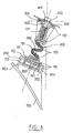
Selon une autre caractéristique avantageuse de l'invention, comme le montre la figure 5, le dispositif de fixation est capable, grâce au ressort 200, de subir une grande variété d'élongations selon l'axe ZZ et de flexions, en absorbant les efforts lors du montage.According to another advantageous characteristic of the invention, as shown in FIG. 5, the fixing device is capable, thanks to the
Le ressort 200 peut si nécessaire être remplacé en cas de défaillance.
Enfin à l'autre extrémité du dispositif de fixation, la partie 130 du corps 100 loge une frette 600 et un joint torique d'étanchéité 700.Finally, at the other end of the fixing device, the
Plus précisément, la partie 130 du corps possède un alésage généralement cylindrique taraudé, d'axe ZZ, dans lequel est reçue la frette 600. Dans la face d'extrémité de la partie 130 est formée une gorge 132, qui reçoit le joint d'étanchéité 700.More specifically, the
La frette 600 est représentée sur la figure 4. Le diamètre extérieur de la frette correspond à celui de l'alésage de la partie 130, et son alésage intérieur est taraudé pour coopérer avec la vis 500. Ainsi la frette 600 est filetée sur ses faces extérieures et intérieures, et possède de préférence une rainure de blocage 610 en haut du filetage extérieur.The
Une fois vissée dans le corps 100, la frette reste en place, bloquée par la rainure de blocage.Once screwed into the
La frette est avantageusement réalisée en laiton, et a pour objet d'éviter que la partie 130 du corps, réalisée dans un matériau plastique, ne se fende lors du serrage de la vis 500.The hoop is advantageously made of brass, and its object is to prevent the
Sur la carrosserie 400 du véhicule, la zone d'attache 450 représentée sur la figure 1, reçoit la partie 130 du corps du dispositif.On the
La zone d'attache 450 est plane, et présente une ouverture circulaire ordinaire 451, apte à recevoir la vis 500.The
Le dispositif de fixation qui vient d'être décrit est utilisé de la façon suivante lors du montage ou du démontage de la fixation.The fixing device which has just been described is used in the following manner during the mounting or dismounting of the binding.
Le ressort 200, la frette 600 et le joint 700 sont montés initialement sur le corps 100 du dispositif, comme indiqué précédemment.The
La partie 120 du corps est encliquetée dans le logement 350 du boîtier 300 de feu. Puis la vis 500 est engagée dans l'ouverture 451 de la carrosserie, et vissée dans la frette 600 du corps 100. Sous l'effet du serrage de la vis 500, la partie 120 du corps abritant le ressort 200 se déforme, et l'embase 130 du corps vient s'appliquer contre la zone d'attache 450 de la carrosserie, maintenant ainsi le boîtier 300 en place.The
On remarquera que, selon une caractéristique avantageuse de l'invention, la fixation du boîtier 300 sur la carrosserie 400 nécessite seulement deux pièces indépendantes, à savoir la vis 500 et le corps 100 comportant le ressort 200, la frette 600 et le joint 700.It will be noted that, according to an advantageous characteristic of the invention, the fixing of the
Selon une variante de l'invention, représentée sur la figure 6, il est possible de réaliser un dispositif de fixation ne comprenant pas de frette. La vis 500 coopère alors directement avec le corps 100 du dispositif. Le matériau du corps 100 est alors adapté.According to a variant of the invention, shown in Figure 6, it is possible to produce a fixing device not comprising a hoop. The
Selon une autre variante du dispositif de fixation représentée sur la figure 7, la partie 130 du corps de la fixation comprend un goujon 510 inamovible d'axe ZZ, débouchant par la face d'extrémité de la partie 130, vers le haut sur la figure 7. Le goujon 510 présente une tige filetée 511 et une zone d'attache 515 avec la partie 130 du corps. A l'extrémité de la zone d'attache 515 une tête 516 permet d'immobiliser le goujon dans le corps 100, moulé autour du goujon.According to another variant of the fixing device shown in FIG. 7, the
Dans cette variante de l'invention, le montage du feu de signalisation sur la carrosserie du véhicule est réalisé en vissant un écrou sur la tige filetée 511 du dispositif, insérée dans la zone d'attache 450 de la carrosserie. Cette variante permet de ne pas utiliser de frette tout en évitant de fendre le corps lors du montage de la fixation.In this variant of the invention, the mounting of the signaling light on the vehicle body is carried out by screwing a nut on the threaded
Selon d'autres variantes, il est possible de réaliser le corps 100 du dispositif et le ressort 200, ainsi que la frette 600 dans des matériaux différents, et de les assembler par des techniques différentes.According to other variants, it is possible to produce the
Ainsi le corps 100 peut par exemple être surmoulé sur la frette 600 et/ou le ressort 200, qui constituent alors des inserts.Thus the
Par ailleurs, on peut éviter de recourir à un ressort spécifique 200, en adaptant le matériau du corps 100 au moins dans la partie intermédiaire 120, par exemple en le renforçant par incorporation d'agents de renfort dans la matière plastique.Furthermore, it is possible to avoid using a
Claims (10)
Applications Claiming Priority (3)
| Application Number | Priority Date | Filing Date | Title |
|---|---|---|---|
| FR9605986A FR2748708B1 (en) | 1996-05-14 | 1996-05-14 | FIXING OF LIGHTS ON MOTOR VEHICLE BODIES, COMPRISING AN ACCORDION SPRING |
| FR9605986 | 1996-05-14 | ||
| PCT/FR1997/000918 WO1998054028A1 (en) | 1996-05-14 | 1997-05-26 | Device for fixing a light unit on a car body comprising an extensible spring |
Publications (2)
| Publication Number | Publication Date |
|---|---|
| EP0807547A1 true EP0807547A1 (en) | 1997-11-19 |
| EP0807547B1 EP0807547B1 (en) | 2000-07-12 |
Family
ID=9492114
Family Applications (1)
| Application Number | Title | Priority Date | Filing Date |
|---|---|---|---|
| EP97401052A Expired - Lifetime EP0807547B1 (en) | 1996-05-14 | 1997-05-12 | Light fixation using a zigzag folded spring on the vehicle body |
Country Status (5)
| Country | Link |
|---|---|
| US (1) | US6135619A (en) |
| EP (1) | EP0807547B1 (en) |
| DE (1) | DE69702478T2 (en) |
| ES (1) | ES2150201T3 (en) |
| WO (1) | WO1998054028A1 (en) |
Cited By (5)
| Publication number | Priority date | Publication date | Assignee | Title |
|---|---|---|---|---|
| EP0838367A3 (en) * | 1996-10-23 | 1999-05-06 | Volkswagen Aktiengesellschaft | Fixation device for vehicle lights or headlamps |
| FR2901516A1 (en) * | 2006-05-24 | 2007-11-30 | Peugeot Citroen Automobiles Sa | Optical unit e.g. light source assembly, positioning device for motor vehicle, has piece formed by supporting flange that forms sealing joint on external surface of rear wall of case, when optical unit is assembled on structure |
| WO2009049784A1 (en) * | 2007-10-12 | 2009-04-23 | Böllhoff Verbindungstechnik GmbH | Rapid-action fixing device |
| WO2014207650A1 (en) * | 2013-06-26 | 2014-12-31 | Sabic Innovative Plastics Ip B.V. | Headlamp mounting bracket energy absorber |
| WO2016133814A1 (en) * | 2015-02-20 | 2016-08-25 | Illinois Tool Works Inc. | Fastening device |
Families Citing this family (13)
| Publication number | Priority date | Publication date | Assignee | Title |
|---|---|---|---|---|
| JP4500415B2 (en) * | 2000-08-08 | 2010-07-14 | 株式会社協豊製作所 | Instrument panel mounting bracket |
| KR100410696B1 (en) * | 2000-11-02 | 2003-12-18 | 현대자동차주식회사 | Mounting structure of head lamp for automobile |
| FR2844758B1 (en) * | 2002-09-20 | 2006-04-14 | Valeo Vision | MOTOR VEHICLE PROJECTOR HAVING ENERGY ABSORPTION MEANS |
| US6695396B1 (en) * | 2002-11-01 | 2004-02-24 | General Motors Corporation | Adjustable fastener assembly |
| DE10310773B4 (en) * | 2003-03-12 | 2014-08-07 | Volkswagen Ag | Housing for a vehicle light |
| DE10330921A1 (en) * | 2003-07-09 | 2005-02-10 | Opel Eisenach Gmbh | Rear light for fastening to vehicle, employs screwed connection points and has indirect support via adaptor penetrated by threaded bolt |
| DE102006039627B3 (en) * | 2006-08-24 | 2008-01-17 | Faurecia Kunststoffe Automobilsysteme Gmbh | Automotive headlamp fixture incorporates two elastic fittings cambered in opposite directions |
| DE102008021754B4 (en) * | 2008-04-30 | 2020-08-20 | Volkswagen Ag | Holding device and holding element of a holding device |
| KR101063381B1 (en) * | 2008-07-21 | 2011-09-07 | 현대자동차주식회사 | Vehicle Headlamp Breaking Mechanism |
| US11639039B1 (en) | 2016-02-04 | 2023-05-02 | Maurice Paperi | Matching pieces and kits for repairing broken structures and related methods |
| EP3501894A1 (en) * | 2017-12-19 | 2019-06-26 | Ningbo Geely Automobile Research & Development Co., Ltd. | A device for suspension of a lamp in a vehicle |
| US11148578B2 (en) * | 2018-03-25 | 2021-10-19 | Maurice Paperi | Universal mounting tabs and kits for automotive components |
| DE102018210222A1 (en) | 2018-06-22 | 2019-12-24 | Bayerische Motoren Werke Aktiengesellschaft | motor vehicle |
Citations (3)
| Publication number | Priority date | Publication date | Assignee | Title |
|---|---|---|---|---|
| US2138076A (en) * | 1937-02-08 | 1938-11-29 | Hall C M Lamp Co | Lighting unit mounting |
| FR899047A (en) * | 1943-10-21 | 1945-05-15 | Headlight adjuster arranged in the fender of a vehicle | |
| DE2258312B1 (en) * | 1972-11-29 | 1974-03-28 | Westfaelische Metall Industrie | MOTOR VEHICLE HEADLIGHTS |
Family Cites Families (4)
| Publication number | Priority date | Publication date | Assignee | Title |
|---|---|---|---|---|
| FR795615A (en) * | 1934-08-31 | 1936-03-18 | Bosch Robert | Recessed headlight for vehicles |
| FR813614A (en) * | 1936-02-10 | 1937-06-05 | Mounting device for automobile headlights | |
| FR894131A (en) * | 1942-04-24 | 1944-12-14 | Bosch Gmbh Robert | Headlight recessed from the front in the body of a vehicle, in particular an automobile |
| DE3803933A1 (en) * | 1987-02-11 | 1988-08-25 | Carello Spa | Motor vehicle headlight |
-
1997
- 1997-05-12 EP EP97401052A patent/EP0807547B1/en not_active Expired - Lifetime
- 1997-05-12 DE DE69702478T patent/DE69702478T2/en not_active Expired - Fee Related
- 1997-05-12 ES ES97401052T patent/ES2150201T3/en not_active Expired - Lifetime
- 1997-05-26 US US09/230,424 patent/US6135619A/en not_active Expired - Fee Related
- 1997-05-26 WO PCT/FR1997/000918 patent/WO1998054028A1/en active Application Filing
Patent Citations (3)
| Publication number | Priority date | Publication date | Assignee | Title |
|---|---|---|---|---|
| US2138076A (en) * | 1937-02-08 | 1938-11-29 | Hall C M Lamp Co | Lighting unit mounting |
| FR899047A (en) * | 1943-10-21 | 1945-05-15 | Headlight adjuster arranged in the fender of a vehicle | |
| DE2258312B1 (en) * | 1972-11-29 | 1974-03-28 | Westfaelische Metall Industrie | MOTOR VEHICLE HEADLIGHTS |
Cited By (8)
| Publication number | Priority date | Publication date | Assignee | Title |
|---|---|---|---|---|
| EP0838367A3 (en) * | 1996-10-23 | 1999-05-06 | Volkswagen Aktiengesellschaft | Fixation device for vehicle lights or headlamps |
| FR2901516A1 (en) * | 2006-05-24 | 2007-11-30 | Peugeot Citroen Automobiles Sa | Optical unit e.g. light source assembly, positioning device for motor vehicle, has piece formed by supporting flange that forms sealing joint on external surface of rear wall of case, when optical unit is assembled on structure |
| WO2009049784A1 (en) * | 2007-10-12 | 2009-04-23 | Böllhoff Verbindungstechnik GmbH | Rapid-action fixing device |
| WO2014207650A1 (en) * | 2013-06-26 | 2014-12-31 | Sabic Innovative Plastics Ip B.V. | Headlamp mounting bracket energy absorber |
| US9174568B2 (en) | 2013-06-26 | 2015-11-03 | Sabic Global Technologies B.V. | Headlamp mounting bracket energy absorber |
| CN105339208A (en) * | 2013-06-26 | 2016-02-17 | 沙特基础全球技术有限公司 | Headlamp mounting bracket energy absorber |
| CN105339208B (en) * | 2013-06-26 | 2017-03-08 | 沙特基础全球技术有限公司 | Thermoplasticity energy absorption headlight mounting bracket and the vehicle including this support |
| WO2016133814A1 (en) * | 2015-02-20 | 2016-08-25 | Illinois Tool Works Inc. | Fastening device |
Also Published As
| Publication number | Publication date |
|---|---|
| WO1998054028A1 (en) | 1998-12-03 |
| ES2150201T3 (en) | 2000-11-16 |
| DE69702478D1 (en) | 2000-08-17 |
| DE69702478T2 (en) | 2000-12-07 |
| EP0807547B1 (en) | 2000-07-12 |
| US6135619A (en) | 2000-10-24 |
Similar Documents
| Publication | Publication Date | Title |
|---|---|---|
| EP0807547B1 (en) | Light fixation using a zigzag folded spring on the vehicle body | |
| EP3580416A1 (en) | Device for holding ajar a flap on a stationary element of a vehicle body | |
| FR2493959A1 (en) | PROJECTOR FOR MOTOR VEHICLE | |
| FR2608107A2 (en) | ADJUSTABLE FASTENING DEVICE, PARTICULARLY FOR MOTOR VEHICLE PROJECTOR | |
| EP0751040B1 (en) | Improved device for mounting a vehicle signalling light | |
| FR2478718A1 (en) | Sliding vehicle door stop - uses pin and biassed co-operating cylinder to prevent vibration in transit | |
| EP0679553A1 (en) | Three dimensionally adjustable fixation device for a lighting or signaling vehicle device | |
| EP0604306B1 (en) | Vehicle light with weather strip applied against the vehicle body | |
| FR2748708A1 (en) | FIXING FIRE ON BODY OF MOTOR VEHICLE, COMPRISING AN ACCORDION SPRING | |
| FR2620090A3 (en) | System for fixing a light device, more particularly a lighting or signalling device, particularly for a motor vehicle | |
| CA2515573A1 (en) | Fixing device with a clip | |
| FR2796427A1 (en) | Pre-mounting device for assembling windscreen wiper mechanisms comprises supports for screw with flexible strip between them which is bent over and fits into nut. | |
| EP1607271B1 (en) | Lead -through device for a thin metal sheet | |
| FR2739816A1 (en) | PROJECTOR FOR VEHICLES | |
| EP1378639B1 (en) | Exhaust pipe suspension hanger for a vehicle and a vehicle equipped with such a suspension hanger | |
| EP2446155A1 (en) | Attachment device having a plastic nut | |
| FR2925418A1 (en) | Signal light case for motor vehicle, has fixation and maintaining element i.e. nut, assuring maintenance of sealing joint against upper edge of circular central recess and pressing sealing joint against upper edge of recess | |
| EP1800949B1 (en) | Light unit for a vehicle provided with a rod having a positioning portion and a portion for fixing it to the car body | |
| FR2786233A1 (en) | Linkage from pivoted lever, particularly between brake pedal and brake servo in motor vehicles | |
| EP1277617A2 (en) | Attachment for a vehicle exterior rear view mirror | |
| FR2848622A1 (en) | Vehicle e.g. car, door panel fixing method, has screw made up of rigid material inserted into bore of water-tightness unit through opening of vehicle body, such that screw is maintained panel against cell of body | |
| FR2737763A1 (en) | Sealing joint between duct and container with opening - has circular side wall whose external surface has peripheral groove delimiting two wall parts, one inclined and other parallel to geometrical axis, lip moulded to side wall defining central opening | |
| WO2013160459A1 (en) | Member for attaching an accessory onto a mounting and the mounting onto a structure | |
| EP0524105B1 (en) | Adjusting mechanism, fixedly mounted to a body, in particular for adjusting the orientation of vehicle headlights | |
| EP3807546A1 (en) | Compliant panel edge for receiving a nut clamp |
Legal Events
| Date | Code | Title | Description |
|---|---|---|---|
| PUAI | Public reference made under article 153(3) epc to a published international application that has entered the european phase |
Free format text: ORIGINAL CODE: 0009012 |
|
| AK | Designated contracting states |
Kind code of ref document: A1 Designated state(s): DE ES GB IT |
|
| 17P | Request for examination filed |
Effective date: 19980427 |
|
| GRAG | Despatch of communication of intention to grant |
Free format text: ORIGINAL CODE: EPIDOS AGRA |
|
| 17Q | First examination report despatched |
Effective date: 19990824 |
|
| GRAG | Despatch of communication of intention to grant |
Free format text: ORIGINAL CODE: EPIDOS AGRA |
|
| GRAH | Despatch of communication of intention to grant a patent |
Free format text: ORIGINAL CODE: EPIDOS IGRA |
|
| GRAH | Despatch of communication of intention to grant a patent |
Free format text: ORIGINAL CODE: EPIDOS IGRA |
|
| GRAA | (expected) grant |
Free format text: ORIGINAL CODE: 0009210 |
|
| AK | Designated contracting states |
Kind code of ref document: B1 Designated state(s): DE ES GB IT |
|
| REF | Corresponds to: |
Ref document number: 69702478 Country of ref document: DE Date of ref document: 20000817 |
|
| GBT | Gb: translation of ep patent filed (gb section 77(6)(a)/1977) |
Effective date: 20000727 |
|
| ITF | It: translation for a ep patent filed |
Owner name: SOCIETA' ITALIANA BREVETTI S.P.A. |
|
| REG | Reference to a national code |
Ref country code: ES Ref legal event code: FG2A Ref document number: 2150201 Country of ref document: ES Kind code of ref document: T3 |
|
| PLBE | No opposition filed within time limit |
Free format text: ORIGINAL CODE: 0009261 |
|
| STAA | Information on the status of an ep patent application or granted ep patent |
Free format text: STATUS: NO OPPOSITION FILED WITHIN TIME LIMIT |
|
| 26N | No opposition filed | ||
| REG | Reference to a national code |
Ref country code: GB Ref legal event code: IF02 |
|
| PGFP | Annual fee paid to national office [announced via postgrant information from national office to epo] |
Ref country code: GB Payment date: 20050428 Year of fee payment: 9 |
|
| PGFP | Annual fee paid to national office [announced via postgrant information from national office to epo] |
Ref country code: DE Payment date: 20050510 Year of fee payment: 9 |
|
| PGFP | Annual fee paid to national office [announced via postgrant information from national office to epo] |
Ref country code: ES Payment date: 20050512 Year of fee payment: 9 |
|
| PG25 | Lapsed in a contracting state [announced via postgrant information from national office to epo] |
Ref country code: GB Free format text: LAPSE BECAUSE OF NON-PAYMENT OF DUE FEES Effective date: 20060512 |
|
| PG25 | Lapsed in a contracting state [announced via postgrant information from national office to epo] |
Ref country code: ES Free format text: LAPSE BECAUSE OF NON-PAYMENT OF DUE FEES Effective date: 20060513 |
|
| PGFP | Annual fee paid to national office [announced via postgrant information from national office to epo] |
Ref country code: IT Payment date: 20060531 Year of fee payment: 10 |
|
| PG25 | Lapsed in a contracting state [announced via postgrant information from national office to epo] |
Ref country code: DE Free format text: LAPSE BECAUSE OF NON-PAYMENT OF DUE FEES Effective date: 20061201 |
|
| GBPC | Gb: european patent ceased through non-payment of renewal fee |
Effective date: 20060512 |
|
| REG | Reference to a national code |
Ref country code: ES Ref legal event code: FD2A Effective date: 20060513 |
|
| PG25 | Lapsed in a contracting state [announced via postgrant information from national office to epo] |
Ref country code: IT Free format text: LAPSE BECAUSE OF NON-PAYMENT OF DUE FEES Effective date: 20070512 |