EP0807461B1 - Liegender Rohrreaktor zur Behandlung von pastösem Gut oder Schüttgut - Google Patents
Liegender Rohrreaktor zur Behandlung von pastösem Gut oder Schüttgut Download PDFInfo
- Publication number
- EP0807461B1 EP0807461B1 EP97107615A EP97107615A EP0807461B1 EP 0807461 B1 EP0807461 B1 EP 0807461B1 EP 97107615 A EP97107615 A EP 97107615A EP 97107615 A EP97107615 A EP 97107615A EP 0807461 B1 EP0807461 B1 EP 0807461B1
- Authority
- EP
- European Patent Office
- Prior art keywords
- reactor
- hollow shaft
- balls
- reactor chamber
- treatment
- Prior art date
- Legal status (The legal status is an assumption and is not a legal conclusion. Google has not performed a legal analysis and makes no representation as to the accuracy of the status listed.)
- Expired - Lifetime
Links
Images

Classifications
-
- B—PERFORMING OPERATIONS; TRANSPORTING
- B01—PHYSICAL OR CHEMICAL PROCESSES OR APPARATUS IN GENERAL
- B01J—CHEMICAL OR PHYSICAL PROCESSES, e.g. CATALYSIS OR COLLOID CHEMISTRY; THEIR RELEVANT APPARATUS
- B01J19/00—Chemical, physical or physico-chemical processes in general; Their relevant apparatus
- B01J19/18—Stationary reactors having moving elements inside
- B01J19/20—Stationary reactors having moving elements inside in the form of helices, e.g. screw reactors
-
- B—PERFORMING OPERATIONS; TRANSPORTING
- B01—PHYSICAL OR CHEMICAL PROCESSES OR APPARATUS IN GENERAL
- B01J—CHEMICAL OR PHYSICAL PROCESSES, e.g. CATALYSIS OR COLLOID CHEMISTRY; THEIR RELEVANT APPARATUS
- B01J2208/00—Processes carried out in the presence of solid particles; Reactors therefor
- B01J2208/00008—Controlling the process
- B01J2208/00017—Controlling the temperature
- B01J2208/00106—Controlling the temperature by indirect heat exchange
- B01J2208/00168—Controlling the temperature by indirect heat exchange with heat exchange elements outside the bed of solid particles
- B01J2208/00212—Plates; Jackets; Cylinders
-
- B—PERFORMING OPERATIONS; TRANSPORTING
- B01—PHYSICAL OR CHEMICAL PROCESSES OR APPARATUS IN GENERAL
- B01J—CHEMICAL OR PHYSICAL PROCESSES, e.g. CATALYSIS OR COLLOID CHEMISTRY; THEIR RELEVANT APPARATUS
- B01J2208/00—Processes carried out in the presence of solid particles; Reactors therefor
- B01J2208/00008—Controlling the process
- B01J2208/00017—Controlling the temperature
- B01J2208/00513—Controlling the temperature using inert heat absorbing solids in the bed
-
- B—PERFORMING OPERATIONS; TRANSPORTING
- B01—PHYSICAL OR CHEMICAL PROCESSES OR APPARATUS IN GENERAL
- B01J—CHEMICAL OR PHYSICAL PROCESSES, e.g. CATALYSIS OR COLLOID CHEMISTRY; THEIR RELEVANT APPARATUS
- B01J2219/00—Chemical, physical or physico-chemical processes in general; Their relevant apparatus
- B01J2219/18—Details relating to the spatial orientation of the reactor
- B01J2219/182—Details relating to the spatial orientation of the reactor horizontal
Definitions
- the invention relates to a non-rotating patient Tube reactor for mechanical and / or thermal treatment of pasty goods or bulk goods according to the generic term of Claim 1.
- non-rotating lying Tube reactors with moving stratification and Prefer funding agencies.
- non-rotating tubular reactors compared to rotary tubular reactors comparatively narrow distributions of the residence times achieved be caused by the formation of chambers in the reactor space raid weirs can still be improved.
- materials that change during treatment liquefy at least briefly or because of their consistency can show a flowable behavior in this way Short-circuit current through the reactor can be avoided.
- the return of the packing is required, but also brings heat loss by reheating the Balls are balanced again on the inlet side have to.
- US-A-4 862 601 and US-A-3401 923 describe tubular reactors for treatment from Schuffgut under presence of grinding and / or cleaning bodies in Reaklorraum.
- the object of the invention the basis for a non-rotating horizontal tube reactor type mentioned in the beginning to create a possibility by the ratio of heating surface to reactor content to improve limited material throughput.
- the invention has in the treatment of pasty Materials and those that are at temperatures below or in the treatment temperature range for gluing and Baking tend to have the advantage that by moving the Balls in the reactor room a permanent cleaning of the Inner wall of the reactor and the conveying and shifting elements takes place, causing caking and blockages in the reactor be avoided.
- By moving the balls Coarse grains and agglomerations of the material to be treated open minded; the material is ground. This way the reaction rates and the turnover rates significantly increased.
- Balls from the hot end of the reactor to the front of the reactor act as a heat transfer medium through the heat of Reactor parts with lower heat requirements (reactor end)
- the material throughput can be the same Reactor size can be increased.
- Fig. 1 is a schematic longitudinal section through a horizontal tube reactor 1 shown with a fixed jacket tube 2.
- the reactor space 3 formed within the casing tube 2 is by a front end wall 4 and and a rear End wall 5 limited.
- In the end walls 4 and 5 is one Shaft 6 rotatably mounted within the reactor space 3, between the end walls 4 and 5, as a hollow shaft 7 is trained.
- the casing tube 2 is - as not specifically shown - in heated in a known manner from the outside; the Coat be designed as a double jacket in which a Heat transfer medium circulates. The heat entered there becomes through the jacket 2 to that located in the reactor chamber 3 Treated goods delivered by one at the front end of the reactor 1 provided material entry 8 entered and after passing through the reactor space 3 through one of the rear end wall 4 adjacent material discharge 9 is carried out.
- the hollow shaft 7 as a conveying and shifting device trained and equipped for this purpose with paddles 10; Instead of such paddles, a screw conveyor could also be used be provided.
- the paddle 10 is used to treat Well promoted in the direction of arrows 11.
- Screw conveyor 13 Within the shell 12 of the hollow shaft 7 is one Screw conveyor 13 arranged, the direction of conveyance (arrow 14) of those promoting the good (arrows 11) in the Reactor room is opposite.
- the screw conveyor 13 is firmly connected to the jacket 12 of the hollow shaft 7 and rotated so in the same direction and at the same speed as that Hollow shaft 7.
- the reactor 1 is up to a certain filling level spherical packing 15 filled.
- the fill level is depending on the use of the reactor and the type of treating good. Also depending on the purpose of the Reactor, the packing 15 from different Materials, e.g. Steel, other metals, ceramics or the like exist; the diameter of the balls can 20 to 25 mm.
- the balls 15 are with the treat material in the direction of conveyance (arrow 11) conveyed through the reactor room 3.
- a screening device 16 e.g. in the form of a perforated or slotted plate, covered, through which the treated goods can fall through Bullets 15 but are held back.
- the discharge of the good is by the movement of the balls 15 on the Screening device 16 still favors.
- the sensor 17 consists of a circular segment-shaped, shovel-like receiving device, which, similar to the paddles 10, on the jacket 12 of the hollow shaft 7 is attached and with its radially outer end moved along the inner wall of the casing tube 2. In the area this transducer 17 has a jacket 12 of the hollow shaft Opening 18 on.
- the Hollow shaft 7 in the direction of arrow 19 from the bottom of the Casing tube 2 lying balls 15 a certain number recorded; they roll with continued rotation of the Hollow shaft 7 along the curved bottom surface of the Transducer 17 radially inwards. Through the opening 18 get the picked up balls. 15 'in the interior of the Hollow shaft 7 and so in the area of influence of the inner screw 13, through which they in the direction of arrow 14 (Fig. 1) Entry end of the reactor 1 are transported. There has the tubular casing 12 at the end of the inner screw 13 again an opening 20 through which the balls 15 ' exit again in the reactor room 3 and get there can add freshly added goods.
- the reactor chamber 3 can in the axial direction by weir-like Walls can be divided into individual chambers; in particular should such a weir 21 before the material discharge 9 be arranged to equalize the discharge of both the material and the balls.
Landscapes
- Chemical & Material Sciences (AREA)
- Organic Chemistry (AREA)
- Chemical Kinetics & Catalysis (AREA)
- Physical Or Chemical Processes And Apparatus (AREA)
- Treatment Of Sludge (AREA)
- Processing Of Solid Wastes (AREA)
- Muffle Furnaces And Rotary Kilns (AREA)
- Crushing And Grinding (AREA)
- Control And Other Processes For Unpacking Of Materials (AREA)
- Drying Of Solid Materials (AREA)
- Devices And Processes Conducted In The Presence Of Fluids And Solid Particles (AREA)
- Apparatuses For Bulk Treatment Of Fruits And Vegetables And Apparatuses For Preparing Feeds (AREA)
- Disintegrating Or Milling (AREA)
Description
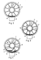
- Fig. 1
- einen schematischen Längsschnitt durch einen Liegenden Rohrreaktor gemäß der Erfindung,
- Fig. 2
- einen Querschnitt entlang der Linie A-A in Fig. 1,
- Fig. 3
- einen Querschnitt entlang der Linie B-B in Fig. 1 und
- Fig. 4
- einen Querschnitt entlang der Linie C-C in Fig. 1.
Claims (1)
- Nichtdrehender Rohrreaktor (1) mit horizontaler Achse zur mechanischen und/oder thermischen Behandlung von pastösem Gut oder Schüttgut unter Anwesenheit von kugelförmigen Mahl- undloder Abreinigungskörpem im Reaktorraummit einer den Reaktorraum (3) axial durchsetzenden Hohlwelle (7), an deren Außenfläche Mittel zur Förderung bzw. Umschichtung des Materials und der kugelförmigen Körper (15) angeordnet sind und durch deren Innenraum die kugelförmigen Körper (15) entgegen der Förderrichtung des Materials gefördert werden,wobei die Hohlwelle (7) am Austragsende (9) für das Material einen Aufnehmer (17) zur Ausförderung der kugelförmigen Körper (15') aus dem Reaktorraum (3) und eine Durchbrechung (18) für deren Eintritt in die Hohlwelle (7) sowie am Eintragsende (8) für das Material eine Durchbrechung (20) für den Austritt der kugelförmigen Körper (15) in den Reaktorraum (3) aufweist undwobei innerhalb der Hohlwelle (7) als Fördermittel zur Rückführung der kugelförmigen Körper (15) eine Schnecke (13) mit der Förderrichtung (11) im Reaktorraum (3) entgegengesetzter Förderrichtung (14) angeordnet ist.
Applications Claiming Priority (2)
| Application Number | Priority Date | Filing Date | Title |
|---|---|---|---|
| DE19620116 | 1996-05-18 | ||
| DE19620116A DE19620116A1 (de) | 1996-05-18 | 1996-05-18 | Verfahren und Vorrichtung zur Behandlung von pastösem Gut oder Schüttgut in einem liegenden Rohrreaktor |
Publications (4)
| Publication Number | Publication Date |
|---|---|
| EP0807461A2 EP0807461A2 (de) | 1997-11-19 |
| EP0807461A3 EP0807461A3 (de) | 1998-05-13 |
| EP0807461B1 true EP0807461B1 (de) | 2001-08-01 |
| EP0807461B9 EP0807461B9 (de) | 2002-09-11 |
Family
ID=7794699
Family Applications (1)
| Application Number | Title | Priority Date | Filing Date |
|---|---|---|---|
| EP97107615A Expired - Lifetime EP0807461B9 (de) | 1996-05-18 | 1997-05-09 | Liegender Rohrreaktor zur Behandlung von pastösem Gut oder Schüttgut |
Country Status (7)
| Country | Link |
|---|---|
| EP (1) | EP0807461B9 (de) |
| JP (1) | JPH1047859A (de) |
| AT (1) | ATE203688T1 (de) |
| DE (2) | DE19620116A1 (de) |
| DK (1) | DK0807461T3 (de) |
| ES (1) | ES2160280T3 (de) |
| GR (1) | GR3036948T3 (de) |
Families Citing this family (4)
| Publication number | Priority date | Publication date | Assignee | Title |
|---|---|---|---|---|
| WO2001096503A2 (de) | 2000-06-15 | 2001-12-20 | Clariant International Ltd | Additive zur verbesserung von kaltfliesseigenschaften und lagerstabilität von rohölen |
| AU2003203063A1 (en) * | 2002-01-29 | 2003-09-02 | N.V. Claves Consult | Method and installation for gasifying combustible materials |
| US7507386B2 (en) | 2003-02-20 | 2009-03-24 | Werkstoff & Funktion Grimmel Wassertechnik Gmbh | Catalytic reactor |
| JP2023177473A (ja) * | 2022-06-02 | 2023-12-14 | 吉佳エンジニアリング株式会社 | 流動体の撹拌装置 |
Family Cites Families (6)
| Publication number | Priority date | Publication date | Assignee | Title |
|---|---|---|---|---|
| DE375461C (de) * | 1921-08-02 | 1923-05-14 | Heinrich Koppers Dr Ing | Verfahren und Vorrichtung zur Destillation fester Brennstoffe, insbesondere bei niederen Temperaturen |
| DE452138C (de) * | 1921-10-04 | 1927-11-03 | Hermann Frischer | Verfahren zur Herstellung von Ameisensaeure, Essigsaeure und Flusssaeure |
| US3401923A (en) * | 1966-02-17 | 1968-09-17 | Wilmot Eng Co | Dryer |
| GB2088243B (en) * | 1980-11-25 | 1984-05-10 | Rtl Contactor Holding Sa | Rotary contactor |
| US4862601A (en) * | 1988-01-20 | 1989-09-05 | Atlantic Richfield Company | Particulate solids dryer with recycled hot-pebble heat exchange medium |
| GB9012463D0 (en) * | 1990-06-05 | 1990-07-25 | North Roger D | Drying apparatus/method |
-
1996
- 1996-05-18 DE DE19620116A patent/DE19620116A1/de not_active Ceased
-
1997
- 1997-05-09 EP EP97107615A patent/EP0807461B9/de not_active Expired - Lifetime
- 1997-05-09 DK DK97107615T patent/DK0807461T3/da active
- 1997-05-09 AT AT97107615T patent/ATE203688T1/de not_active IP Right Cessation
- 1997-05-09 ES ES97107615T patent/ES2160280T3/es not_active Expired - Lifetime
- 1997-05-09 DE DE59704170T patent/DE59704170D1/de not_active Expired - Lifetime
- 1997-05-14 JP JP9124178A patent/JPH1047859A/ja active Pending
-
2001
- 2001-10-18 GR GR20010401818T patent/GR3036948T3/el not_active IP Right Cessation
Also Published As
| Publication number | Publication date |
|---|---|
| EP0807461A3 (de) | 1998-05-13 |
| DK0807461T3 (da) | 2001-11-12 |
| ES2160280T3 (es) | 2001-11-01 |
| GR3036948T3 (en) | 2002-01-31 |
| EP0807461B9 (de) | 2002-09-11 |
| EP0807461A2 (de) | 1997-11-19 |
| DE59704170D1 (de) | 2001-09-06 |
| DE19620116A1 (de) | 1997-11-20 |
| JPH1047859A (ja) | 1998-02-20 |
| ATE203688T1 (de) | 2001-08-15 |
Similar Documents
| Publication | Publication Date | Title |
|---|---|---|
| DE3248384C2 (de) | Einrichtung zur Entwässerung von Feststoffen | |
| DE2611251A1 (de) | Vorrichtung zur stofftrennung | |
| DE2012645A1 (de) | Vorrichtung zum Extrudieren von schwer extrudierbaren Materialien, insbesondere von Kunststoffabfällen | |
| DE2160962C3 (de) | Trommeltrockner zum Trocknen von Schlamm | |
| DE2100248C3 (de) | Einrichtung zur Wärme-, Kälte,- und/oder Stoffbehandlung körnigen, rieselfähigen Gutes | |
| WO2021254550A1 (de) | Schneckenförderer; verfahren zur beseitigung bzw. verhinderung von ablagerungen an einer innenwand eines rohres eines schneckenförderers | |
| EP1622706B1 (de) | Mischvorrichtung und Mischverfahren das diese Vorrichtung verwendet | |
| DE2048226B2 (de) | Drehrohrofen zur Gewinnung von Fluorwasserstoffsäure | |
| EP0807461B1 (de) | Liegender Rohrreaktor zur Behandlung von pastösem Gut oder Schüttgut | |
| EP2011563A1 (de) | Mischtrockner und/oder Reaktor | |
| DE6750481U (de) | Einrichtung fuer die beschickung von drehtrommeloefen zur verbrennung von schlammigen, teigigen oder halbfluessigen abfallstoffen | |
| DE2208443C2 (de) | Senkrechter Mischbehälter für Kohle-Brikettiergut | |
| DE3104872A1 (de) | Vorrichtung zur herstellung einer glasartigen bzw. verglasten schlacke | |
| DE2946904C2 (de) | Von außen beheiz- oder kühlbares, drehbares Wärmetauscherrohr zum Wärmebehandeln von pulvrigem bis körnigem, rieselfähigem, ggf. angeschlämmtem Gut | |
| DE1567297C3 (de) | Vorrichtung zum Temperieren einer Zuckerfüllmasse | |
| DE2548647A1 (de) | Vorrichtung zur steuerung eines teilchenfoermigen feststoffstromes | |
| DE2118231C3 (de) | Drehtrommel zum Granulieren schüttfähiger, feinkörniger und/oder staubförmiger Materialien | |
| DE102018132084A1 (de) | Schneckenförderer; Verfahren zur Beseitigung bzw. Verhinderung von Ablagerungen an einer Innenwand eines Rohres eines Schneckenförderers | |
| DE2822533A1 (de) | Festkoerper-vollmanteldekantierzentrifuge | |
| DE2058774C3 (de) | Verfahren und Vorrichtung zur Wärmebehandlung von rieselfähig-festen, teigigen oder flüssigen Stoffen | |
| EP1714694B2 (de) | Grossvolumiger Mischer / Reaktor | |
| DE2013203A1 (de) | ||
| DE1769645C (de) | Gegenstromverdampfer. Ausscheidung aus: 1692547 | |
| EP0215342B1 (de) | Verfahren und Vorrichtung für die chemische, mechanische und/oder thermische Behandlung von Pulvern | |
| DE2855307A1 (de) | Vorrichtung zur kontaktbehandlung von fluessigkeiten und feststoffen mit fluessigkeiten |
Legal Events
| Date | Code | Title | Description |
|---|---|---|---|
| PUAI | Public reference made under article 153(3) epc to a published international application that has entered the european phase |
Free format text: ORIGINAL CODE: 0009012 |
|
| AK | Designated contracting states |
Kind code of ref document: A2 Designated state(s): AT BE CH DE DK ES FR GB GR IT LI NL SE |
|
| PUAL | Search report despatched |
Free format text: ORIGINAL CODE: 0009013 |
|
| AK | Designated contracting states |
Kind code of ref document: A3 Designated state(s): AT BE CH DE DK ES FR GB GR IT LI NL SE |
|
| 17P | Request for examination filed |
Effective date: 19980602 |
|
| 17Q | First examination report despatched |
Effective date: 20000328 |
|
| GRAG | Despatch of communication of intention to grant |
Free format text: ORIGINAL CODE: EPIDOS AGRA |
|
| GRAG | Despatch of communication of intention to grant |
Free format text: ORIGINAL CODE: EPIDOS AGRA |
|
| GRAH | Despatch of communication of intention to grant a patent |
Free format text: ORIGINAL CODE: EPIDOS IGRA |
|
| GRAH | Despatch of communication of intention to grant a patent |
Free format text: ORIGINAL CODE: EPIDOS IGRA |
|
| GRAA | (expected) grant |
Free format text: ORIGINAL CODE: 0009210 |
|
| AK | Designated contracting states |
Kind code of ref document: B1 Designated state(s): AT BE CH DE DK ES FR GB GR IT LI NL SE |
|
| REF | Corresponds to: |
Ref document number: 203688 Country of ref document: AT Date of ref document: 20010815 Kind code of ref document: T |
|
| REG | Reference to a national code |
Ref country code: CH Ref legal event code: EP |
|
| REF | Corresponds to: |
Ref document number: 59704170 Country of ref document: DE Date of ref document: 20010906 |
|
| REG | Reference to a national code |
Ref country code: CH Ref legal event code: NV Representative=s name: PATENTANWAELTE SCHAAD, BALASS, MENZL & PARTNER AG |
|
| REG | Reference to a national code |
Ref country code: ES Ref legal event code: FG2A Ref document number: 2160280 Country of ref document: ES Kind code of ref document: T3 |
|
| REG | Reference to a national code |
Ref country code: DK Ref legal event code: T3 |
|
| GBT | Gb: translation of ep patent filed (gb section 77(6)(a)/1977) |
Effective date: 20011106 |
|
| ET | Fr: translation filed | ||
| REG | Reference to a national code |
Ref country code: GB Ref legal event code: IF02 |
|
| REG | Reference to a national code |
Ref country code: GR Ref legal event code: EP Ref document number: 20010401818 Country of ref document: GR |
|
| PLBE | No opposition filed within time limit |
Free format text: ORIGINAL CODE: 0009261 |
|
| STAA | Information on the status of an ep patent application or granted ep patent |
Free format text: STATUS: NO OPPOSITION FILED WITHIN TIME LIMIT |
|
| 26N | No opposition filed | ||
| PGFP | Annual fee paid to national office [announced via postgrant information from national office to epo] |
Ref country code: NL Payment date: 20090520 Year of fee payment: 13 Ref country code: ES Payment date: 20090522 Year of fee payment: 13 Ref country code: DK Payment date: 20090526 Year of fee payment: 13 |
|
| PGFP | Annual fee paid to national office [announced via postgrant information from national office to epo] |
Ref country code: SE Payment date: 20090525 Year of fee payment: 13 Ref country code: IT Payment date: 20090527 Year of fee payment: 13 Ref country code: FR Payment date: 20090519 Year of fee payment: 13 |
|
| PGFP | Annual fee paid to national office [announced via postgrant information from national office to epo] |
Ref country code: BE Payment date: 20090526 Year of fee payment: 13 |
|
| PGFP | Annual fee paid to national office [announced via postgrant information from national office to epo] |
Ref country code: CH Payment date: 20090525 Year of fee payment: 13 |
|
| PGFP | Annual fee paid to national office [announced via postgrant information from national office to epo] |
Ref country code: GR Payment date: 20090430 Year of fee payment: 13 Ref country code: GB Payment date: 20090528 Year of fee payment: 13 |
|
| PGFP | Annual fee paid to national office [announced via postgrant information from national office to epo] |
Ref country code: AT Payment date: 20100520 Year of fee payment: 14 |
|
| BERE | Be: lapsed |
Owner name: MAX *AICHER UMWELTTECHNIK G.M.B.H. Effective date: 20100531 |
|
| REG | Reference to a national code |
Ref country code: NL Ref legal event code: V1 Effective date: 20101201 |
|
| REG | Reference to a national code |
Ref country code: CH Ref legal event code: PL |
|
| REG | Reference to a national code |
Ref country code: DK Ref legal event code: EBP |
|
| GBPC | Gb: european patent ceased through non-payment of renewal fee |
Effective date: 20100509 |
|
| EUG | Se: european patent has lapsed | ||
| REG | Reference to a national code |
Ref country code: FR Ref legal event code: ST Effective date: 20110131 |
|
| PG25 | Lapsed in a contracting state [announced via postgrant information from national office to epo] |
Ref country code: LI Free format text: LAPSE BECAUSE OF NON-PAYMENT OF DUE FEES Effective date: 20100531 Ref country code: CH Free format text: LAPSE BECAUSE OF NON-PAYMENT OF DUE FEES Effective date: 20100531 |
|
| PG25 | Lapsed in a contracting state [announced via postgrant information from national office to epo] |
Ref country code: BE Free format text: LAPSE BECAUSE OF NON-PAYMENT OF DUE FEES Effective date: 20100531 Ref country code: SE Free format text: LAPSE BECAUSE OF NON-PAYMENT OF DUE FEES Effective date: 20100510 Ref country code: GR Free format text: LAPSE BECAUSE OF NON-PAYMENT OF DUE FEES Effective date: 20101202 Ref country code: NL Free format text: LAPSE BECAUSE OF NON-PAYMENT OF DUE FEES Effective date: 20101201 Ref country code: IT Free format text: LAPSE BECAUSE OF NON-PAYMENT OF DUE FEES Effective date: 20100509 |
|
| PG25 | Lapsed in a contracting state [announced via postgrant information from national office to epo] |
Ref country code: DK Free format text: LAPSE BECAUSE OF NON-PAYMENT OF DUE FEES Effective date: 20100531 |
|
| PG25 | Lapsed in a contracting state [announced via postgrant information from national office to epo] |
Ref country code: FR Free format text: LAPSE BECAUSE OF NON-PAYMENT OF DUE FEES Effective date: 20100531 |
|
| REG | Reference to a national code |
Ref country code: ES Ref legal event code: FD2A Effective date: 20110715 |
|
| PG25 | Lapsed in a contracting state [announced via postgrant information from national office to epo] |
Ref country code: GB Free format text: LAPSE BECAUSE OF NON-PAYMENT OF DUE FEES Effective date: 20100509 Ref country code: ES Free format text: LAPSE BECAUSE OF NON-PAYMENT OF DUE FEES Effective date: 20110705 |
|
| PG25 | Lapsed in a contracting state [announced via postgrant information from national office to epo] |
Ref country code: ES Free format text: LAPSE BECAUSE OF NON-PAYMENT OF DUE FEES Effective date: 20100510 |
|
| REG | Reference to a national code |
Ref country code: AT Ref legal event code: MM01 Ref document number: 203688 Country of ref document: AT Kind code of ref document: T Effective date: 20110509 |
|
| PG25 | Lapsed in a contracting state [announced via postgrant information from national office to epo] |
Ref country code: AT Free format text: LAPSE BECAUSE OF NON-PAYMENT OF DUE FEES Effective date: 20110509 |
|
| REG | Reference to a national code |
Ref country code: DE Ref legal event code: R082 Ref document number: 59704170 Country of ref document: DE Representative=s name: RAU, SCHNECK & HUEBNER PATENTANWAELTE RECHTSAN, DE Ref country code: DE Ref legal event code: R082 Ref document number: 59704170 Country of ref document: DE |
|
| REG | Reference to a national code |
Ref country code: DE Ref legal event code: R082 Ref document number: 59704170 Country of ref document: DE Representative=s name: RAU, SCHNECK & HUEBNER PATENTANWAELTE RECHTSAN, DE Effective date: 20140225 Ref country code: DE Ref legal event code: R081 Ref document number: 59704170 Country of ref document: DE Owner name: MAX AICHER GMBH & CO. KG, DE Free format text: FORMER OWNER: MAX AICHER UMWELTTECHNIK GMBH, 83395 FREILASSING, DE Effective date: 20140312 |
|
| PGFP | Annual fee paid to national office [announced via postgrant information from national office to epo] |
Ref country code: DE Payment date: 20140728 Year of fee payment: 18 |
|
| REG | Reference to a national code |
Ref country code: DE Ref legal event code: R119 Ref document number: 59704170 Country of ref document: DE |
|
| PG25 | Lapsed in a contracting state [announced via postgrant information from national office to epo] |
Ref country code: DE Free format text: LAPSE BECAUSE OF NON-PAYMENT OF DUE FEES Effective date: 20151201 |