EP0807205B1 - Ventiltrieb einer brennkraftmaschine - Google Patents
Ventiltrieb einer brennkraftmaschine Download PDFInfo
- Publication number
- EP0807205B1 EP0807205B1 EP95940952A EP95940952A EP0807205B1 EP 0807205 B1 EP0807205 B1 EP 0807205B1 EP 95940952 A EP95940952 A EP 95940952A EP 95940952 A EP95940952 A EP 95940952A EP 0807205 B1 EP0807205 B1 EP 0807205B1
- Authority
- EP
- European Patent Office
- Prior art keywords
- shaft
- sliding
- axial pin
- shank
- rotating body
- Prior art date
- Legal status (The legal status is an assumption and is not a legal conclusion. Google has not performed a legal analysis and makes no representation as to the accuracy of the status listed.)
- Expired - Lifetime
Links
- 238000002485 combustion reaction Methods 0.000 title claims description 5
- 230000005540 biological transmission Effects 0.000 claims description 14
- UQDJGEHQDNVPGU-UHFFFAOYSA-N serine phosphoethanolamine Chemical compound [NH3+]CCOP([O-])(=O)OCC([NH3+])C([O-])=O UQDJGEHQDNVPGU-UHFFFAOYSA-N 0.000 claims description 3
- 230000007423 decrease Effects 0.000 description 3
- 230000002349 favourable effect Effects 0.000 description 2
- 238000000418 atomic force spectrum Methods 0.000 description 1
- 238000005452 bending Methods 0.000 description 1
- 230000009286 beneficial effect Effects 0.000 description 1
- 238000005553 drilling Methods 0.000 description 1
- 238000009434 installation Methods 0.000 description 1
- 238000000034 method Methods 0.000 description 1
Images
Classifications
-
- F—MECHANICAL ENGINEERING; LIGHTING; HEATING; WEAPONS; BLASTING
- F01—MACHINES OR ENGINES IN GENERAL; ENGINE PLANTS IN GENERAL; STEAM ENGINES
- F01L—CYCLICALLY OPERATING VALVES FOR MACHINES OR ENGINES
- F01L1/00—Valve-gear or valve arrangements, e.g. lift-valve gear
- F01L1/34—Valve-gear or valve arrangements, e.g. lift-valve gear characterised by the provision of means for changing the timing of the valves without changing the duration of opening and without affecting the magnitude of the valve lift
- F01L1/344—Valve-gear or valve arrangements, e.g. lift-valve gear characterised by the provision of means for changing the timing of the valves without changing the duration of opening and without affecting the magnitude of the valve lift changing the angular relationship between crankshaft and camshaft, e.g. using helicoidal gear
- F01L1/34413—Valve-gear or valve arrangements, e.g. lift-valve gear characterised by the provision of means for changing the timing of the valves without changing the duration of opening and without affecting the magnitude of the valve lift changing the angular relationship between crankshaft and camshaft, e.g. using helicoidal gear using composite camshafts, e.g. with cams being able to move relative to the camshaft
-
- F—MECHANICAL ENGINEERING; LIGHTING; HEATING; WEAPONS; BLASTING
- F01—MACHINES OR ENGINES IN GENERAL; ENGINE PLANTS IN GENERAL; STEAM ENGINES
- F01L—CYCLICALLY OPERATING VALVES FOR MACHINES OR ENGINES
- F01L1/00—Valve-gear or valve arrangements, e.g. lift-valve gear
- F01L1/34—Valve-gear or valve arrangements, e.g. lift-valve gear characterised by the provision of means for changing the timing of the valves without changing the duration of opening and without affecting the magnitude of the valve lift
- F01L1/344—Valve-gear or valve arrangements, e.g. lift-valve gear characterised by the provision of means for changing the timing of the valves without changing the duration of opening and without affecting the magnitude of the valve lift changing the angular relationship between crankshaft and camshaft, e.g. using helicoidal gear
- F01L1/356—Valve-gear or valve arrangements, e.g. lift-valve gear characterised by the provision of means for changing the timing of the valves without changing the duration of opening and without affecting the magnitude of the valve lift changing the angular relationship between crankshaft and camshaft, e.g. using helicoidal gear making the angular relationship oscillate, e.g. non-homokinetic drive
Definitions
- the invention relates to a valve train Internal combustion engine and in particular a valve train an internal combustion engine in which a rotating body, preferably a cam, by a shaft, preferably a camshaft, can be driven such that it at a constant speed of the internal combustion engine during a A cyclical increase and decrease of the Undergoes rotational speed, thereby making it variable To provide valve control.
- a rotating body preferably a cam
- a shaft preferably a camshaft
- Transmission element consists of a bolt, the one first section of circular cross section for storage in the axially parallel bore and at one end is flattened along a second section so that on this second section two parallel sliding surfaces result in engagement with the sliding guide.
- a transmission element known from WO 91/05941 consists of a cylindrical bolt and a rectangular sliding block, the two parallel Sliding surfaces for engaging the sliding guide provides.
- the cylindrical bolt is with a Part of its length is stored in the axially parallel bore and with the part protruding from this hole in one Bore of the sliding block added.
- Both known transmission elements have the disadvantage that the overall arrangement takes up too much installation space, if the sliding surfaces are dimensioned sufficiently, that there is satisfactory wear behavior sets.
- Step GB-A-1 311 562 discloses a valve train according to the first part of claim 1.
- the object of the invention is a valve train To provide a good wear behavior takes up as little space as possible.
- At least one transmission element of the Valve drive arranged parallel to the axis of rotation Axial pin with a shank that at least faces one one side along the sliding guide over the circumference of the Shaft also has extending sliding vane that is rotatably connected to the shaft.
- That used according to the invention in the valve train Transmission element has a relatively large sliding surface in the longitudinal direction of the sliding guide (long length) at the same time compact dimensions with regard to the width of the Slideway (small width) and the diameter of the Shaft on.
- the width can be chosen to be smaller are as with a separate sliding block according to WO 91/05941, since none of the shaft in the transverse direction of the Sliding material from outside for Increasing the width contributes.
- the sliding surfaces by flattening of the bolt according to DE 43 20 126 A1 is sufficient Dimensioning of the sliding vane in the longitudinal direction of the Slideway without influencing the diameter of the shaft be realized purely for reasons of strength can be relatively small because the shaft is practically only on Shear rather than bending.
- the large length-width ratio works like a cant counter to the sliding vane in the sliding guide and results thus favorable sliding conditions.
- the small width of the Gliding flag and that despite favorable sliding conditions small diameters of the shaft allow an arrangement of the transmission element directly in a cam near the Cam tip even when the cam is on Series engines have the usual pointed profile.
- the sliding vane is preferably made of the same material the shaft. However, it is fundamental possible, different for shaft and slide flag choose materials, for example, under the Point of view of the cheapest friction pairings, and the two elements by suitable connection methods to connect firmly.
- the size of the forces and the respective engagement radii and the type of Storage and the respective friction pairings can Diameter of the shaft larger or smaller than that Width of the slide flag transverse to the longitudinal direction of the Be sliding.
- the shaft is preferably a camshaft and the Rotating body a cam for actuating a Gas exchange valve. This makes it extremely compact Device for variable valve control provided.
- the intermediate link can be designed so that its outer contour in no operating position over the Outer contour of the cam protrudes. This enables the Use of this embodiment in bucket tappet motors.
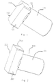
- Fig. 1 shows a first embodiment of a Transmission element for transmitting a rotary movement in a sliding guide. It is a Axial pin 100 with a shaft 101 and a sliding vane 102.
- the shaft 101 has a circular cross section and is made of the same material with the sliding vane 102 manufactured, which is cuboid and one to the axis of cylindrical shaft 101 vertically extending first Has side edge 103 which extends to one side over the Circumference of the circular cross section of the shaft 101 extends.
- the axial pin 100 thus has an L shape.
- One to the first side edge 103 and to the axis of the cylindrical shaft 101 vertically extending second Side edge corresponds to that in the illustration in FIG. 1 Diameter of the shaft 101, but can also be from this differ.
- the second side edge 104 is shorter than that first side edge 103.
- Fig. 2 shows a second embodiment of a Transmission element for transmitting a rotary movement in a sliding guide.
- This second axial pin 200 has also via a cylindrical shaft 201 and a cuboid slide flag 202 with side edges 203 and 204 and differs from the first axial pin 100 only in that the longer side edge 203 to both sides around the circumference of the cylindrical shaft 201 extends beyond.
- the axial pin 200 thus has one T shape on.
- the shaft 201 is shown in the illustration in FIG. 2 arranged in the middle of the longer side edge 203, he can but also be offset to one side.
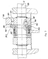
- Fig. 3 shows an embodiment of a valve train with an L-shaped axial pin 100 according to FIG. 1 and a T-shaped axial pin 200 according to FIG. 2.
- the L-shaped axial pin 100 is with its shaft 101 in a recess is inserted around the circumference of a camshaft 120 and engages with the sliding vane 102 in the sliding guide an intermediate link 140, the longer one Side edge 103 runs in the longitudinal direction of the sliding guide and faces away from the camshaft. This will create a Axial pin 100 arrangement close to the axis enables and at the same time a large sliding surface is provided.
- the T-shaped axial pin 200 is in with its shaft 201 a bore 111 of a cam 110 inserted on the Camshaft 120 is mounted.
- the slide flag 202 engages in the sliding guide of the intermediate member 140, the longer side edge 203 in the longitudinal direction of the sliding guide runs. This creates a symmetrical force curve enables and at the same time a large sliding surface provided.
Landscapes
- Engineering & Computer Science (AREA)
- Mechanical Engineering (AREA)
- General Engineering & Computer Science (AREA)
- Valve-Gear Or Valve Arrangements (AREA)
- Valve Device For Special Equipments (AREA)
Description
- Fig. 1
- eine perspektivische Darstellung einer ersten Ausführungsform eines Axialstifts mit einer L-Form zeigt,
- Fig. 2
- eine perspektivische Darstellung einer zweiten Ausführungsform eines Axialstifts mit einer T-Form zeigt und
- Fig. 3
- ein Ausführungsbeispiel eines Ventiltriebs mit einem Axialstift mit einer L-Form und einem Axialstift mit einer T-Form zeigt.
- 100
- L-förmiger Axialstift
- 101
- Schaft
- 102
- Gleitfahne
- 103
- erste Seitenkante
- 104
- zweite Seitenkante
- 110
- Drehkörper, Nocken
- 111
- Bohrung
- 120
- Welle, Nockenwelle
- 140
- Drehkörper
- 200
- T-förmiger Axialstift
- 201
- Schaft
- 202
- Gleitfahne
- 203
- erste Seitenkante
- 204
- zweite Seitenkante
Claims (5)
- Ventiltrieb einer Brennkraftmaschinewobei zumindest ein Übertragungselement (100, 200) einen parallel zur Drehachse (D) angeordneten Axialstift (100,200) mit einem Schaft (101, 201) umfaßt, undmit einer eine Drehachse (D) aufweisenden antreibenden Welle (120),mit einem durch die Welle (120) angetriebenen Drehkörper (110) undmit einem zu dem Drehkörper (110) und/oder der Welle (120) desaxierten Zwischenglied (140), das mit der Welle (120) über eine erste Gleitführung und ein erstes Übertragungselement (100, 200) und/oder mit dem Drehkörper (110) über eine zweite Gleitführung und ein zweites Übertragungselement (100, 200) antriebsmäßig verbunden ist,
der Axialstift (100, 200) eine sich zumindest zu einer Seite längs der Gleitführung über den Umfang des Schafts (101, 201) hinaus erstreckende Gleitfahne (102, 202) aufweist, dadurch gekennzeichnet, daß die Gleitfahne drehfest mit dem Schaft (101, 202) verbunden ist. - Ventiltrieb nach Anspruch 1, dadurch gekennzeichnet, daß die Gleitfahne (101, 202) materialeinheitlich mit dem Schaft (101, 201) ausgebildet ist.
- Ventiltrieb nach Anspruch 1 oder 2, dadurch gekennzeichnet, daß die Gleitfahne (102) sich zu einer Seite über den Umfang des Schafts (101)) hinaus erstreckt, so daß der Axialstift (100) eine L-Form aufweist.
- Ventiltrieb nach Anspruch 1 oder 2, dadurch gekennzeichnet, daß die Gleitfahne (202) sich zu beiden Seiten über den Umfang des Schafts (201)) hinaus erstreckt, so daß der Axialstift (200) eine T-Form aufweist.
- Ventiltrieb nach einem der vorstehenden Ansprüche, dadurch gekennzeichnet, daß die Welle (120) eine Nockenwelle und der Drehkörper (110) ein Nocken zur Betätigung eines Gaswechselventils ist.
Applications Claiming Priority (5)
| Application Number | Priority Date | Filing Date | Title |
|---|---|---|---|
| DE19502834 | 1995-01-30 | ||
| DE19502834A DE19502834A1 (de) | 1995-01-30 | 1995-01-30 | Anordnung zur Lagerung eines Bauteils |
| DE19528756 | 1995-08-04 | ||
| DE19528756 | 1995-08-04 | ||
| PCT/DE1995/001782 WO1996023962A1 (de) | 1995-01-30 | 1995-12-12 | Ventiltrieb einer brennkraftmaschine |
Publications (2)
| Publication Number | Publication Date |
|---|---|
| EP0807205A1 EP0807205A1 (de) | 1997-11-19 |
| EP0807205B1 true EP0807205B1 (de) | 2000-02-16 |
Family
ID=26011958
Family Applications (1)
| Application Number | Title | Priority Date | Filing Date |
|---|---|---|---|
| EP95940952A Expired - Lifetime EP0807205B1 (de) | 1995-01-30 | 1995-12-12 | Ventiltrieb einer brennkraftmaschine |
Country Status (4)
| Country | Link |
|---|---|
| EP (1) | EP0807205B1 (de) |
| AU (1) | AU4252396A (de) |
| DE (1) | DE59507827D1 (de) |
| WO (1) | WO1996023962A1 (de) |
Citations (1)
| Publication number | Priority date | Publication date | Assignee | Title |
|---|---|---|---|---|
| GB1311562A (en) * | 1969-06-27 | 1973-03-28 | Ass Eng Ltd | Device for moving a cam relative to its driving shaft |
Family Cites Families (4)
| Publication number | Priority date | Publication date | Assignee | Title |
|---|---|---|---|---|
| GB2166842A (en) * | 1984-11-09 | 1986-05-14 | Ford Motor Co | Drive mechanism for variable valve timing |
| DE3525862A1 (de) * | 1985-07-19 | 1987-01-29 | Kloeckner Humboldt Deutz Ag | Vorrichtung zur verstellung des einspritzzeitpunkts von brennkraftmaschinen |
| GB8923181D0 (en) * | 1989-10-13 | 1989-11-29 | Rover Group | An internal combustion engine |
| JP2644408B2 (ja) * | 1991-03-29 | 1997-08-25 | アーウィン コロステンスキー | 内燃機関の連続可変バルブタイミング機構 |
-
1995
- 1995-12-12 EP EP95940952A patent/EP0807205B1/de not_active Expired - Lifetime
- 1995-12-12 DE DE59507827T patent/DE59507827D1/de not_active Expired - Fee Related
- 1995-12-12 WO PCT/DE1995/001782 patent/WO1996023962A1/de not_active Ceased
- 1995-12-12 AU AU42523/96A patent/AU4252396A/en not_active Abandoned
Patent Citations (1)
| Publication number | Priority date | Publication date | Assignee | Title |
|---|---|---|---|---|
| GB1311562A (en) * | 1969-06-27 | 1973-03-28 | Ass Eng Ltd | Device for moving a cam relative to its driving shaft |
Also Published As
| Publication number | Publication date |
|---|---|
| EP0807205A1 (de) | 1997-11-19 |
| AU4252396A (en) | 1996-08-21 |
| WO1996023962A1 (de) | 1996-08-08 |
| DE59507827D1 (de) | 2000-03-23 |
Similar Documents
| Publication | Publication Date | Title |
|---|---|---|
| DE2029911C2 (de) | Vorrichtung zur Steuerung eines Nockens relativ zu einer Antriebswelle, insbesondere zur Veränderung der Ein- und Auslaßventil-Öffnungszeiten in einer Brennkraftmaschine | |
| DE3825074C1 (de) | ||
| EP2739830B1 (de) | Ventiltrieb einer brennkraftmaschine, brennkraftmaschine sowie verfahren zur herstellung eines entsprechenden ventiltriebs | |
| DE3039946C2 (de) | Vorrichtung zum Verhindern einer Drehbewegung von mindestens zwei, an einer Nockenwelle einer Brennkraftmaschine angreifenden Rollenstößeln | |
| DE69417150T2 (de) | Vorrichtung zur Verstellung der relativen Drehlage zwischen einer Kurbelwelle und einer Nockenwelle einer Brennkraftmaschine | |
| EP1511922A1 (de) | Getriebe mit zwei ineinander angeordneten drehscheiben, die durch eine taumelscheibe miteinander verbunden sind | |
| DE69421170T2 (de) | Nockenspitze mit exzentrischer drehbewegung | |
| DE68925342T2 (de) | Ventilantriebsvorrichtung für Brennkraftmaschine | |
| DE4419557C1 (de) | Brennkraftmaschine mit variabler Ventilsteuerung | |
| EP0865566B1 (de) | Ventiltrieb einer brennkraftmaschine | |
| DE102004041751B4 (de) | Nockenwellenversteller mit einer Kupplung zwischen einer Stellwelle und einem Verstellgetriebe | |
| DE102008046821B4 (de) | Kurbelwelle für eine Brennkraftmaschine mit varibaler Verdichtung und Brennkraftmaschine mit variabler Verdichtung | |
| DE19502836C2 (de) | Brennkraftmaschine | |
| EP0807205B1 (de) | Ventiltrieb einer brennkraftmaschine | |
| EP0797726B1 (de) | Ventiltrieb einer brennkraftmaschine | |
| DE102014214125B4 (de) | Stelleinrichtung zur Verstellung von Steuerzeiten einer Brennkraftmaschine | |
| DE102020210260A1 (de) | Schiebenockensystem | |
| DE10109234A1 (de) | Variable Ventilvorrichtung eines Verbrennungsmotors | |
| DE102018214698B4 (de) | Ventiltrieb für eine Brennkraftmaschine | |
| EP0807206A1 (de) | Brennkraftmaschine | |
| DE69409888T2 (de) | Auswuchtmechanismus für eine Brennkraftmaschine | |
| DE102015210080A1 (de) | Nockenwellenmodul mit trennbarem Schiebeelement und Verfahren zur Montage eines Nockenwellenmoduls | |
| DE102015212691B4 (de) | Nockenwelle mit Rastelement sowie Verfahren zur Montage einer Nockenwelle | |
| DE19830930A1 (de) | Vorrichtung zur Winkelverstellung einer Welle gegenüber ihrem Antriebsrad | |
| DE19501172C2 (de) | Drehantriebsanordnung |
Legal Events
| Date | Code | Title | Description |
|---|---|---|---|
| PUAI | Public reference made under article 153(3) epc to a published international application that has entered the european phase |
Free format text: ORIGINAL CODE: 0009012 |
|
| 17P | Request for examination filed |
Effective date: 19970822 |
|
| AK | Designated contracting states |
Kind code of ref document: A1 Designated state(s): DE FR GB IT |
|
| GRAG | Despatch of communication of intention to grant |
Free format text: ORIGINAL CODE: EPIDOS AGRA |
|
| GRAG | Despatch of communication of intention to grant |
Free format text: ORIGINAL CODE: EPIDOS AGRA |
|
| GRAH | Despatch of communication of intention to grant a patent |
Free format text: ORIGINAL CODE: EPIDOS IGRA |
|
| 17Q | First examination report despatched |
Effective date: 19990429 |
|
| GRAH | Despatch of communication of intention to grant a patent |
Free format text: ORIGINAL CODE: EPIDOS IGRA |
|
| GRAA | (expected) grant |
Free format text: ORIGINAL CODE: 0009210 |
|
| AK | Designated contracting states |
Kind code of ref document: B1 Designated state(s): DE FR GB IT |
|
| PG25 | Lapsed in a contracting state [announced via postgrant information from national office to epo] |
Ref country code: IT Free format text: LAPSE BECAUSE OF FAILURE TO SUBMIT A TRANSLATION OF THE DESCRIPTION OR TO PAY THE FEE WITHIN THE PRESCRIBED TIME-LIMIT;WARNING: LAPSES OF ITALIAN PATENTS WITH EFFECTIVE DATE BEFORE 2007 MAY HAVE OCCURRED AT ANY TIME BEFORE 2007. THE CORRECT EFFECTIVE DATE MAY BE DIFFERENT FROM THE ONE RECORDED. Effective date: 20000216 Ref country code: GB Free format text: LAPSE BECAUSE OF FAILURE TO SUBMIT A TRANSLATION OF THE DESCRIPTION OR TO PAY THE FEE WITHIN THE PRESCRIBED TIME-LIMIT Effective date: 20000216 Ref country code: FR Free format text: LAPSE BECAUSE OF FAILURE TO SUBMIT A TRANSLATION OF THE DESCRIPTION OR TO PAY THE FEE WITHIN THE PRESCRIBED TIME-LIMIT Effective date: 20000216 |
|
| REF | Corresponds to: |
Ref document number: 59507827 Country of ref document: DE Date of ref document: 20000323 |
|
| EN | Fr: translation not filed | ||
| GBV | Gb: ep patent (uk) treated as always having been void in accordance with gb section 77(7)/1977 [no translation filed] |
Effective date: 20000216 |
|
| PLBE | No opposition filed within time limit |
Free format text: ORIGINAL CODE: 0009261 |
|
| STAA | Information on the status of an ep patent application or granted ep patent |
Free format text: STATUS: NO OPPOSITION FILED WITHIN TIME LIMIT |
|
| 26N | No opposition filed | ||
| PGFP | Annual fee paid to national office [announced via postgrant information from national office to epo] |
Ref country code: DE Payment date: 20060630 Year of fee payment: 11 |
|
| PG25 | Lapsed in a contracting state [announced via postgrant information from national office to epo] |
Ref country code: DE Free format text: LAPSE BECAUSE OF NON-PAYMENT OF DUE FEES Effective date: 20070703 |