EP0807030B1 - Antriebsvorrichtung, insbesondere radantrieb für kettenfahrzeuge - Google Patents
Antriebsvorrichtung, insbesondere radantrieb für kettenfahrzeuge Download PDFInfo
- Publication number
- EP0807030B1 EP0807030B1 EP96902931A EP96902931A EP0807030B1 EP 0807030 B1 EP0807030 B1 EP 0807030B1 EP 96902931 A EP96902931 A EP 96902931A EP 96902931 A EP96902931 A EP 96902931A EP 0807030 B1 EP0807030 B1 EP 0807030B1
- Authority
- EP
- European Patent Office
- Prior art keywords
- hub
- planetary gear
- hub carrier
- drive
- drive device
- Prior art date
- Legal status (The legal status is an assumption and is not a legal conclusion. Google has not performed a legal analysis and makes no representation as to the accuracy of the status listed.)
- Expired - Lifetime
Links
Images

Classifications
-
- B—PERFORMING OPERATIONS; TRANSPORTING
- B60—VEHICLES IN GENERAL
- B60K—ARRANGEMENT OR MOUNTING OF PROPULSION UNITS OR OF TRANSMISSIONS IN VEHICLES; ARRANGEMENT OR MOUNTING OF PLURAL DIVERSE PRIME-MOVERS IN VEHICLES; AUXILIARY DRIVES FOR VEHICLES; INSTRUMENTATION OR DASHBOARDS FOR VEHICLES; ARRANGEMENTS IN CONNECTION WITH COOLING, AIR INTAKE, GAS EXHAUST OR FUEL SUPPLY OF PROPULSION UNITS IN VEHICLES
- B60K7/00—Disposition of motor in, or adjacent to, traction wheel
- B60K7/0015—Disposition of motor in, or adjacent to, traction wheel the motor being hydraulic
-
- B—PERFORMING OPERATIONS; TRANSPORTING
- B60—VEHICLES IN GENERAL
- B60K—ARRANGEMENT OR MOUNTING OF PROPULSION UNITS OR OF TRANSMISSIONS IN VEHICLES; ARRANGEMENT OR MOUNTING OF PLURAL DIVERSE PRIME-MOVERS IN VEHICLES; AUXILIARY DRIVES FOR VEHICLES; INSTRUMENTATION OR DASHBOARDS FOR VEHICLES; ARRANGEMENTS IN CONNECTION WITH COOLING, AIR INTAKE, GAS EXHAUST OR FUEL SUPPLY OF PROPULSION UNITS IN VEHICLES
- B60K17/00—Arrangement or mounting of transmissions in vehicles
- B60K17/04—Arrangement or mounting of transmissions in vehicles characterised by arrangement, location or kind of gearing
- B60K17/043—Transmission unit disposed in on near the vehicle wheel, or between the differential gear unit and the wheel
- B60K17/046—Transmission unit disposed in on near the vehicle wheel, or between the differential gear unit and the wheel with planetary gearing having orbital motion
-
- B—PERFORMING OPERATIONS; TRANSPORTING
- B62—LAND VEHICLES FOR TRAVELLING OTHERWISE THAN ON RAILS
- B62D—MOTOR VEHICLES; TRAILERS
- B62D55/00—Endless track vehicles
- B62D55/08—Endless track units; Parts thereof
- B62D55/12—Arrangement, location, or adaptation of driving sprockets
- B62D55/125—Final drives
- B62D55/13—Final drives readily interchangeable modular type
-
- B—PERFORMING OPERATIONS; TRANSPORTING
- B60—VEHICLES IN GENERAL
- B60K—ARRANGEMENT OR MOUNTING OF PROPULSION UNITS OR OF TRANSMISSIONS IN VEHICLES; ARRANGEMENT OR MOUNTING OF PLURAL DIVERSE PRIME-MOVERS IN VEHICLES; AUXILIARY DRIVES FOR VEHICLES; INSTRUMENTATION OR DASHBOARDS FOR VEHICLES; ARRANGEMENTS IN CONNECTION WITH COOLING, AIR INTAKE, GAS EXHAUST OR FUEL SUPPLY OF PROPULSION UNITS IN VEHICLES
- B60K7/00—Disposition of motor in, or adjacent to, traction wheel
- B60K2007/0038—Disposition of motor in, or adjacent to, traction wheel the motor moving together with the wheel axle
-
- B—PERFORMING OPERATIONS; TRANSPORTING
- B60—VEHICLES IN GENERAL
- B60K—ARRANGEMENT OR MOUNTING OF PROPULSION UNITS OR OF TRANSMISSIONS IN VEHICLES; ARRANGEMENT OR MOUNTING OF PLURAL DIVERSE PRIME-MOVERS IN VEHICLES; AUXILIARY DRIVES FOR VEHICLES; INSTRUMENTATION OR DASHBOARDS FOR VEHICLES; ARRANGEMENTS IN CONNECTION WITH COOLING, AIR INTAKE, GAS EXHAUST OR FUEL SUPPLY OF PROPULSION UNITS IN VEHICLES
- B60K7/00—Disposition of motor in, or adjacent to, traction wheel
- B60K2007/0092—Disposition of motor in, or adjacent to, traction wheel the motor axle being coaxial to the wheel axle
Definitions
- the invention relates to a drive device for work machines, especially for tracked vehicles, such as B. bulldozers or the like.
- Turas drive As known, a Turas drive as known. With these Drive devices drive a hydraulic motor over Planetary gear on a sprocket.
- the drive device should, especially in the axial direction, small dimensions have so that they are not the width of a caterpillar, e.g. B. a crawler excavator, protrudes.
- the planetary gear must have a sufficiently large translation, thus achieving a low speed level on the chain wheel becomes.
- the drive device must be equipped with a brake be so that the output when the hydraulic motor is at a standstill is braked. Since the drive device also under extreme external conditions must be used for a Reliable sealing with a long service life ensured become.
- the drive device should be assembled and be easy to maintain. In terms of manufacturing costs must be the number of components of the drive device be as small as possible.
- the present invention is based on the object a drive device for use in tracked vehicles to create, which in particular by one in the Manufacture of inexpensive, compact and easy to install and maintain and reliable design.
- the object underlying the invention is achieved by solved a drive device that the characteristics of Main claim.
- the slow-running radial piston motor works at a speed level that is a multi-stage planetary gear no longer required.
- the radial piston engine is therefore connected to a single-stage planetary gear. Due to the system, this engine also consists of relatively few Components. It builds compact in the axial direction, so that it flange-mounted directly on one side of the hub carrier can.
- a drive shaft connects the cylinder block of the Radial piston motor with the planetary gear, its output member is rotatably connected to the hub.
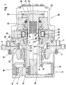
- the in Fig. 1 in longitudinal section and in simplified Represented drive device is particularly for driving a chain wheel of a tracked vehicle, e.g. B. a bulldozer or the like, suitable. It is a drive device that too is common under the name Turas drive.
- a sprocket not shown is non-rotatable connected to a rotating hub 1.
- the hub 1 has a non-rotatable connection on its circumference Variety of threaded holes 2, which are also not Pick up the bolts shown on the sprocket.
- the hub 1 is over two tapered roller bearings 3 on one stationary hub carrier 4 rotatably arranged.
- the tapered roller bearings are mounted in an O arrangement.
- the hub carrier 4 is firmly connected to the vehicle frame, which in detail not apparent from the drawing, but familiar to the expert is.
- a drive shaft is located in the stationary hub carrier 4 6 about a single bearing, especially one Tapered roller bearing 7, rotatably mounted.
- To the drive shaft 6 is followed by a connecting shaft 8.
- With the reference number 9 is the separation point between the drive shaft 6 and the connecting shaft 8 marked.
- the drive shaft 6 is supported on the one side in a floating manner at its free end - lying on the left in the drawing - with an inner central wheel 10 (sun) of a planetary gear 11 rotatably connected.
- the inner central wheel 10 can as in the present case, in one piece with the drive shaft 6 be made.
- the inner central wheel 10 is in constant meshing with planet gears 12, of which one is pictured.
- the planet gears 12 are on roller bearings 13 rotatable on a web 14 of the planetary gear 11 stored.
- the web 14 is also part of a final drive housing 15, which is tightly screwed to the hub 1 and which surrounds the planetary gear 11.
- the planet gears 12 are also in constant mesh with a stationary outer central gear 16 (ring gear) of the planetary gear 11.
- the outer central gear 16 is on the hub carrier 4 in the area of a profile 17 rotatably pushed on and in the axial direction by a nut 18 the tapered roller bearings 3 against a shoulder of the hub carrier 4 countered.
- the drive device is completed by a hydraulic motor 26. It is essential for the drive device that this hydraulic motor consists of a slow-running radial piston motor.
- the swallowing volume of the radial piston engine is approximately 1,180 cm 3 . The maximum speed is approx. 310 1 / min.
- the brake valves are located on the hydraulic motor.
- the hydraulic circuit is open.
- a cylinder block 27 is via a driving profile 28 rotatably connected to the drive shaft 6.
- a driving profile 28 rotatably connected to the drive shaft 6.
- Analogously to this consists of a geometrically identical driving profile 29 a rotationally fixed connection between the cylinder block 27 and the connecting shaft 8.
- Piston 30 mounted radially movable. These are supported from rollers 31 on a stationary cam track 32. over A distributor 33 is used to supply or remove the hydraulic fluid.
- a housing 26 encloses the radial piston motor and, like the cam track 32, is with the hub carrier 4 screwed. For this purpose, there are several in the hub carrier 4 Threaded holes 35 are provided.
- the connecting shaft 8 is axially displaceable. On the one hand, it is under the action of a compression spring 36 and on the other hand a force acts on them from is dependent on a pressure in a pressure chamber 37 prevails. In the drawn (left) end position of the connecting shaft 8 is the pressure prevailing in the pressure chamber 37 high so that a positive locking brake 38 is opened. In the other Case is this form-locking brake 38 by the force the compression spring 36 closed. The positive locking brake 38 acts as a parking brake when the vehicle is stationary.
- the Turas drive explained with a slow running Radial piston motor and a single-stage planetary gear enables the drive of a chain wheel at a highest possible translation.
- the Turas drive builds regarding of space requirements - based on the hub carrier 4 - approximately symmetrical. This means that on the one hand Side of the hydraulic motor 26 flanged and on the other Side the hub 1 together with the planetary gear 11 can be driven in rotation is arranged.
- the drive shaft 6 forms the drive connection between the radial piston motor and the planetary gear 11.
- a major advantage of this Connection is that the diameter of the drive shaft 6 and the hub carrier 4 in the area of this connection can be kept small. As a result, the Diameter of the tapered roller bearings 3 are also small.
- the radial dimensions of the mechanical seal are also 21 small. Because of the peripheral speeds the prevailing diameter ratios and the relative low speed levels also relatively low are, there is a reliable seal with a high lifespan.
- the drive device is compact and is also characterized by great smoothness.
- the planetary gear can be with straight or helical teeth Gears work.
- an additional seal on the drive shaft 6 39 for example a radial shaft seal, run.
- this drive device the web 14 is not part of the final drive housing 15. Rather, the outer central wheel is 16th as an output member of the planetary gear 40 part of the Hub 1.
- the final drive housing 15 is accordingly by the Hub 1 and an additional cover 41 are formed.
- This modified embodiment can then in particular Be used when the output speed level is so low that the maximum possible Translation (as in the embodiment of FIG. 1) can be dispensed with.
Landscapes
- Engineering & Computer Science (AREA)
- Chemical & Material Sciences (AREA)
- Combustion & Propulsion (AREA)
- Transportation (AREA)
- Mechanical Engineering (AREA)
- Retarders (AREA)
- Arrangement Or Mounting Of Propulsion Units For Vehicles (AREA)
- Devices For Conveying Motion By Means Of Endless Flexible Members (AREA)
- Motor Power Transmission Devices (AREA)
- Arrangement And Driving Of Transmission Devices (AREA)
- Automatic Cycles, And Cycles In General (AREA)
- Valve-Gear Or Valve Arrangements (AREA)
Description
- Fig. 1
- eine erste Ausführungsform einer Antriebsvorrichtung in vereinfachter Darstellung, insbesondere für ein Kettenfahrzeug, und
- Fig. 2
- eine weitere Ausführungsform, die insbesondere in der Gestaltung des Endabtriebs gegenüber der Anordnung nach Fig. 1 abweicht.
- 1
- Nabe
- 2
- Gewindebohrung
- 3
- Kegelrollenlager
- 4
- Nabenträger
- 5
- Gewindebohrung
- 6
- Antriebswelle
- 7
- Kegelrollenlager
- 8
- Verbindungswelle
- 9
- Trennstelle
- 10
- inneres Zentralrad
- 11
- Planetengetriebe
- 12
- Planetenrad
- 13
- Wälzlager
- 14
- Steg
- 15
- Endabtriebsgehäuse
- 16
- äußeres Zentralrad
- 17
- Profil
- 18
- Mutter
- 19
- Schulter
- 20
- Spalt
- 21
- Gleitringdichtung
- 22
- rotierender Gleitring
- 23
- Dichtring
- 24
- stationärer Gegenring
- 25
- Dichtring
- 26
- Hydraulikmotor
- 27
- Zylinderblock
- 28
- Mitnahmeprofil
- 29
- Mitnahmeprofil
- 30
- Kolben
- 31
- Rolle
- 32
- Nockenbahn
- 33
- Verteiler
- 34
- Gehäuse
- 35
- Gewindebohrung
- 36
- Druckfeder
- 37
- Druckraum
- 38
- Formschlußbremse
- 39
- Dichtung
- 40
- Planetengetriebe
- 41
- Deckel
Claims (5)
- Radantrieb für Arbeitsmaschinen, insbesondere für Kettenfahrzeuge, bestehend aus einem Hydraulikmotor (26), der über eine Antriebswelle (6) ein inneres Zentralrad (10) eines Planetengetriebes (11, 40) antreibt und dessen Abtriebsglied, das beispielsweise durch einen Steg (14) oder ein äußeres Zentralrad (16) gebildet ist, mit einer Nabe (1), die auf einem stationär angeordneten Nabenträger (4) gelagert ist, drehfest verbunden ist und, gesehen in Fahrzeuglängsrichtung, der Hydraulikmotor (26) auf einer Seite des Nabenträgers (4) angeflanscht ist, während auf der anderen Seite des Nabenträgers (4) das Planetengetriebe (11, 40) und die Nabe (1) angeordnet sind und daß Zwischen dem Nabenträger (4) und der Nabe (1) eine Gleitringdichtung (21) angeordnet ist, dadurch gekennzeichnet, daß die Antriebswelle (6) im Nabenträger (4) fliegend gelagert und der Hydraulikmotor (26) als langsam laufender Radialkolbenmotor und das Planetengetriebe (11, 40) einstufig ausgebildet ist.
- Antriebsvorrichtung nach Anspruch 1, dadurch gekennzeichnet, daß das äußere Zentralrad (16) drehfest mit dem Nabenträger (4) verbunden ist und das Abtriebsglied durch den Steg (14) des Planetengetriebes (11) gebildet wird, der über ein Endabtriebsgehäuse (15) mit der Nabe (1) fest verbunden ist.
- Antriebsvorrichtung nach Anspruch 1, dadurch gekennzeichnet, daß der Steg (14) des Planetengetriebes (40) drehfest mit dem Nabenträger (4) verbunden ist, während das Antriebsglied durch das mit der Nabe (1) drehfest verbundene äußere Zentralrad (16) gebildet wird.
- Antriebsvorrichtung nach Anspruch 1, dadurch gekennzeichnet, daß die Gleitringdichtung (21) aus einem rotierenden Gleitring (22) und einem in eine Ausdrehung der Nabe (1) eingesetzten ersten Dichtring (23) sowie einem stationären Gegenring (24) und einem in eine Ausnehmung des Nabenträgers (4) eingelegten zweiten Dichtring (25) besteht.
- Antriebsvorrichtung nach Anspruch 1, dadurch gekennzeichnet, daß dem Hydraulikmotor (26) eine Formschlußbremse (38) zugeordnet ist.
Applications Claiming Priority (3)
| Application Number | Priority Date | Filing Date | Title |
|---|---|---|---|
| DE19503477A DE19503477A1 (de) | 1995-02-03 | 1995-02-03 | Antriebsvorrichtung, insbesondere Radantrieb für Kettenfahrzeuge |
| DE19503477 | 1995-02-03 | ||
| PCT/EP1996/000331 WO1996023670A1 (de) | 1995-02-03 | 1996-01-27 | Antriebsvorrichtung, insbesondere radantrieb für kettenfahrzeuge |
Publications (2)
| Publication Number | Publication Date |
|---|---|
| EP0807030A1 EP0807030A1 (de) | 1997-11-19 |
| EP0807030B1 true EP0807030B1 (de) | 1999-03-31 |
Family
ID=7753063
Family Applications (1)
| Application Number | Title | Priority Date | Filing Date |
|---|---|---|---|
| EP96902931A Expired - Lifetime EP0807030B1 (de) | 1995-02-03 | 1996-01-27 | Antriebsvorrichtung, insbesondere radantrieb für kettenfahrzeuge |
Country Status (9)
| Country | Link |
|---|---|
| US (1) | US5820506A (de) |
| EP (1) | EP0807030B1 (de) |
| JP (1) | JPH11500381A (de) |
| KR (1) | KR100465422B1 (de) |
| CN (1) | CN1086347C (de) |
| AT (1) | ATE178278T1 (de) |
| BR (1) | BR9607436A (de) |
| DE (2) | DE19503477A1 (de) |
| WO (1) | WO1996023670A1 (de) |
Cited By (2)
| Publication number | Priority date | Publication date | Assignee | Title |
|---|---|---|---|---|
| US6742618B2 (en) | 2000-03-07 | 2004-06-01 | Arctic Cat, Inc. | Snowmobile planetary drive system |
| US6907951B2 (en) | 2000-03-07 | 2005-06-21 | Arctic Cat, Inc. | Snowmobile planetary drive system |
Families Citing this family (20)
| Publication number | Priority date | Publication date | Assignee | Title |
|---|---|---|---|---|
| DE19637570A1 (de) * | 1996-09-14 | 1998-03-19 | Zahnradfabrik Friedrichshafen | Hydrostatisch-mechanischer Radantrieb |
| DE19637590A1 (de) * | 1996-09-14 | 1998-03-19 | Zahnradfabrik Friedrichshafen | Hydrostatisch-mechanischer Fahrantrieb |
| FR2760048B1 (fr) * | 1997-02-27 | 2001-11-16 | Poclain Hydraulics Sa | Entrainement hydraulique pour engin de chantier |
| KR100493536B1 (ko) * | 1997-05-26 | 2005-11-28 | 오꾸보 하구루마 고교 가부시키가이샤 | 감속기장치 |
| DE19814273A1 (de) * | 1998-03-31 | 1999-10-07 | Zahnradfabrik Friedrichshafen | Hydrostatisch mechanischer Antrieb |
| DE19837487C2 (de) * | 1998-08-12 | 2002-07-18 | Lohmann & Stolterfoht Gmbh | Dichtungsanordnung |
| DE19845494C2 (de) † | 1998-10-02 | 2000-07-27 | Krauss Maffei Wegmann Gmbh & C | Kettenfahrzeug |
| DE19903563A1 (de) * | 1999-01-29 | 2000-08-03 | Linde Ag | Hydrostatische Motoreinheit |
| AU2001273656A1 (en) * | 2000-06-30 | 2002-01-14 | Llewellan Anderson | Improved rolling cutter lubrication arrangement |
| FR2813652B1 (fr) * | 2000-09-07 | 2003-06-20 | Poclain Hydraulics Ind | Dispositif d'entrainement comprenant un moteur hydraulique et un reducteur |
| DE102006023577A1 (de) * | 2006-05-19 | 2007-11-22 | Jungheinrich Ag | Radnabenantrieb für Flurförderzeuge |
| DE102006043290A1 (de) * | 2006-09-14 | 2008-03-27 | Zf Friedrichshafen Ag | Hydrostatisch-mechanisches Getriebe |
| DE102006058076A1 (de) * | 2006-12-07 | 2008-06-19 | Zf Friedrichshafen Ag | Hydraulischer Radialkolbenmotor |
| DE102012204795A1 (de) * | 2012-03-26 | 2013-09-26 | Schaeffler Technologies AG & Co. KG | Radnabenmotor mit Potenzialausgleich |
| FR3030381B1 (fr) * | 2014-12-19 | 2018-10-19 | Eugene Albert Laurent | Moteur hydraulique pour roue de vehicule |
| FR3030382B1 (fr) | 2014-12-23 | 2017-01-13 | Poclain Hydraulics Ind | Moteur hydraulique couple |
| JP6408425B2 (ja) | 2015-05-07 | 2018-10-17 | 株式会社小松製作所 | 動力伝達装置およびモータグレーダ |
| CN112498086B (zh) * | 2020-11-30 | 2024-07-05 | 烟台大学 | 一种具有轮毂电机的驱动桥 |
| JP2024545800A (ja) * | 2021-12-16 | 2024-12-12 | ダンフォス アクチ-セルスカブ | ラジアルピストンユニットのためのベアリング装置 |
| FR3136520B1 (fr) * | 2022-06-13 | 2024-08-23 | Poclain Hydraulics Ind | pompe hydraulique améliorée pour entrainement à haute vitesse |
Family Cites Families (16)
| Publication number | Priority date | Publication date | Assignee | Title |
|---|---|---|---|---|
| US2155198A (en) * | 1934-05-05 | 1939-04-18 | William E Lawrence | Variable speed gearing mechanism |
| HU164077B (de) * | 1970-09-28 | 1973-12-28 | ||
| US3865207A (en) * | 1971-04-23 | 1975-02-11 | Hyster Co | Hydraulic feed for wheel motors |
| US3749195A (en) * | 1971-05-03 | 1973-07-31 | Eaton Corp | Hydrostatic drive transmission assembly |
| AR205148A1 (es) * | 1971-11-11 | 1976-04-12 | Renold Ltd | Unidad de rueda motorizada |
| US3770075A (en) * | 1972-03-20 | 1973-11-06 | Eaton Corp | Free wheeling 2-speed motor wheel |
| US4040312A (en) * | 1974-10-29 | 1977-08-09 | Eaton Corporation | Planetary reduction drive unit |
| FR2379394A1 (fr) * | 1977-02-04 | 1978-09-01 | Poclain Hydraulics Sa | Dispositif de fixation et d'entrainement d'un organe de deplacement d'un vehicule |
| JPS5449433A (en) * | 1977-09-28 | 1979-04-18 | Ebara Corp | Hydraulic motor unit for driving crawler |
| DE2744936A1 (de) * | 1977-10-06 | 1979-04-12 | Zahnradfabrik Friedrichshafen | Einzelradantrieb fuer arbeitsmaschinen |
| DE2831458C2 (de) * | 1978-07-18 | 1983-03-24 | Zahnradfabrik Friedrichshafen Ag, 7990 Friedrichshafen | Radantrieb für Arbeitsmaschinen, insbesondere für Kettenfahrzeuge |
| FI73789C (fi) * | 1983-12-07 | 1987-11-09 | Partek Ab | Hydraulisk motor. |
| US4649772A (en) * | 1985-07-05 | 1987-03-17 | Caterpillar Inc. | Planetary wheel drive assembly |
| DE4110161A1 (de) * | 1991-03-27 | 1992-10-01 | Man Nutzfahrzeuge Ag | Antriebseinrichtung fuer fahrzeuge |
| DE4206086B4 (de) * | 1992-02-27 | 2004-04-22 | Linde Ag | Modular aufgebautes Antriebssystem |
| DE4235697A1 (de) * | 1992-09-23 | 1994-03-24 | Linde Ag | Hydromechanisches Antriebsaggregat |
-
1995
- 1995-02-03 DE DE19503477A patent/DE19503477A1/de not_active Withdrawn
-
1996
- 1996-01-27 CN CN96191714A patent/CN1086347C/zh not_active Expired - Fee Related
- 1996-01-27 KR KR1019970705181A patent/KR100465422B1/ko not_active Expired - Fee Related
- 1996-01-27 EP EP96902931A patent/EP0807030B1/de not_active Expired - Lifetime
- 1996-01-27 DE DE59601556T patent/DE59601556D1/de not_active Expired - Lifetime
- 1996-01-27 US US08/875,196 patent/US5820506A/en not_active Expired - Fee Related
- 1996-01-27 AT AT96902931T patent/ATE178278T1/de not_active IP Right Cessation
- 1996-01-27 WO PCT/EP1996/000331 patent/WO1996023670A1/de not_active Ceased
- 1996-01-27 BR BR9607436A patent/BR9607436A/pt not_active Application Discontinuation
- 1996-01-27 JP JP8523232A patent/JPH11500381A/ja active Pending
Cited By (3)
| Publication number | Priority date | Publication date | Assignee | Title |
|---|---|---|---|---|
| US6742618B2 (en) | 2000-03-07 | 2004-06-01 | Arctic Cat, Inc. | Snowmobile planetary drive system |
| US6907951B2 (en) | 2000-03-07 | 2005-06-21 | Arctic Cat, Inc. | Snowmobile planetary drive system |
| US7063639B2 (en) | 2000-03-07 | 2006-06-20 | Arctic Cat Inc. | Snowmobile planetary drive system |
Also Published As
| Publication number | Publication date |
|---|---|
| US5820506A (en) | 1998-10-13 |
| KR100465422B1 (ko) | 2005-05-17 |
| CN1172455A (zh) | 1998-02-04 |
| DE59601556D1 (de) | 1999-05-06 |
| DE19503477A1 (de) | 1996-08-08 |
| JPH11500381A (ja) | 1999-01-12 |
| CN1086347C (zh) | 2002-06-19 |
| ATE178278T1 (de) | 1999-04-15 |
| KR19980701784A (ko) | 1998-06-25 |
| BR9607436A (pt) | 1998-05-26 |
| WO1996023670A1 (de) | 1996-08-08 |
| EP0807030A1 (de) | 1997-11-19 |
Similar Documents
| Publication | Publication Date | Title |
|---|---|---|
| EP0807030B1 (de) | Antriebsvorrichtung, insbesondere radantrieb für kettenfahrzeuge | |
| DE69611313T2 (de) | Schmiersystem für Kraftfahrzeuggetriebe | |
| DE2831458C2 (de) | Radantrieb für Arbeitsmaschinen, insbesondere für Kettenfahrzeuge | |
| DE69321195T2 (de) | Ölschmiersystem für Zwischenachsgetriebe | |
| DE19715278A1 (de) | Getriebeeinheit | |
| DE102011004696A1 (de) | Fahrzeugleistungsübertragungsvorrichtung | |
| DE60312776T2 (de) | Differentialachsanordnung, insbesondere mit einer Schmierpumpe für eine Zwischenachsdifferentialanordnung | |
| EP1776525B1 (de) | Hydrostatischer kreiskolbenmotor | |
| DE112022001054T5 (de) | Elektrozylinder und Arbeitsmaschine | |
| DE2849994A1 (de) | Rotationskolbenmaschine | |
| DE19645650C1 (de) | Gesteinsfräskopf | |
| EP1900971B1 (de) | Hydrostatisch-mechanisches Getriebe | |
| DE102018205862A1 (de) | Getriebe, insbesondere für eine Einzelradantriebseinheit | |
| DE102014210774B4 (de) | Hydraulischer Antrieb mit einer verstellbaren hydraulischen Axialkolbenmaschine in Dry-Case Bauweise | |
| DE4206102C2 (de) | Hydromechanisches Getriebe | |
| DE10325781B4 (de) | Umlaufgetriebe | |
| DE102005041579B4 (de) | Innenzahnradpumpe mit Füllstück | |
| DE3028022A1 (de) | Als radantrieb bestimmte rotationskolbenmaschine | |
| EP1900972B1 (de) | Hydrostatisch-mechanisches Getriebe | |
| DE3307047A1 (de) | Aggregat aus einem druckmittel-kolben-motor und einem umlaufradgetriebe | |
| DE3603773A1 (de) | Zahnradmaschine | |
| EP0475109A1 (de) | Innenzahnradpumpe für Hydraulikflüssigkeit | |
| DE102005002858B4 (de) | Getriebeanordnung einer Antriebsachse eines Kraftfahrzeuges | |
| DD224907A1 (de) | Hydrostatische tandempumpe | |
| WO2020035344A1 (de) | Getriebe, insbesondere für eine einzelradantriebseinheit |
Legal Events
| Date | Code | Title | Description |
|---|---|---|---|
| PUAI | Public reference made under article 153(3) epc to a published international application that has entered the european phase |
Free format text: ORIGINAL CODE: 0009012 |
|
| 17P | Request for examination filed |
Effective date: 19970702 |
|
| AK | Designated contracting states |
Kind code of ref document: A1 Designated state(s): AT BE DE FR GB IT |
|
| 17Q | First examination report despatched |
Effective date: 19971209 |
|
| GRAG | Despatch of communication of intention to grant |
Free format text: ORIGINAL CODE: EPIDOS AGRA |
|
| GRAG | Despatch of communication of intention to grant |
Free format text: ORIGINAL CODE: EPIDOS AGRA |
|
| GRAH | Despatch of communication of intention to grant a patent |
Free format text: ORIGINAL CODE: EPIDOS IGRA |
|
| GRAH | Despatch of communication of intention to grant a patent |
Free format text: ORIGINAL CODE: EPIDOS IGRA |
|
| GRAA | (expected) grant |
Free format text: ORIGINAL CODE: 0009210 |
|
| AK | Designated contracting states |
Kind code of ref document: B1 Designated state(s): AT BE DE FR GB IT |
|
| REF | Corresponds to: |
Ref document number: 178278 Country of ref document: AT Date of ref document: 19990415 Kind code of ref document: T |
|
| GBT | Gb: translation of ep patent filed (gb section 77(6)(a)/1977) |
Effective date: 19990401 |
|
| REF | Corresponds to: |
Ref document number: 59601556 Country of ref document: DE Date of ref document: 19990506 |
|
| ET | Fr: translation filed | ||
| PG25 | Lapsed in a contracting state [announced via postgrant information from national office to epo] |
Ref country code: AT Free format text: LAPSE BECAUSE OF NON-PAYMENT OF DUE FEES Effective date: 20000127 |
|
| PLBE | No opposition filed within time limit |
Free format text: ORIGINAL CODE: 0009261 |
|
| STAA | Information on the status of an ep patent application or granted ep patent |
Free format text: STATUS: NO OPPOSITION FILED WITHIN TIME LIMIT |
|
| 26N | No opposition filed | ||
| PGFP | Annual fee paid to national office [announced via postgrant information from national office to epo] |
Ref country code: BE Payment date: 20010123 Year of fee payment: 6 |
|
| REG | Reference to a national code |
Ref country code: GB Ref legal event code: IF02 |
|
| PG25 | Lapsed in a contracting state [announced via postgrant information from national office to epo] |
Ref country code: BE Free format text: LAPSE BECAUSE OF NON-PAYMENT OF DUE FEES Effective date: 20020131 |
|
| BERE | Be: lapsed |
Owner name: ZF FRIEDRICHSHAFEN A.G. Effective date: 20020131 |
|
| PGFP | Annual fee paid to national office [announced via postgrant information from national office to epo] |
Ref country code: GB Payment date: 20040121 Year of fee payment: 9 |
|
| PG25 | Lapsed in a contracting state [announced via postgrant information from national office to epo] |
Ref country code: GB Free format text: LAPSE BECAUSE OF NON-PAYMENT OF DUE FEES Effective date: 20050127 |
|
| GBPC | Gb: european patent ceased through non-payment of renewal fee |
Effective date: 20050127 |
|
| PGFP | Annual fee paid to national office [announced via postgrant information from national office to epo] |
Ref country code: IT Payment date: 20060131 Year of fee payment: 11 |
|
| PG25 | Lapsed in a contracting state [announced via postgrant information from national office to epo] |
Ref country code: IT Free format text: LAPSE BECAUSE OF NON-PAYMENT OF DUE FEES Effective date: 20070127 |
|
| PGFP | Annual fee paid to national office [announced via postgrant information from national office to epo] |
Ref country code: FR Payment date: 20100208 Year of fee payment: 15 |
|
| PGFP | Annual fee paid to national office [announced via postgrant information from national office to epo] |
Ref country code: DE Payment date: 20100121 Year of fee payment: 15 |
|
| REG | Reference to a national code |
Ref country code: FR Ref legal event code: ST Effective date: 20110930 |
|
| PG25 | Lapsed in a contracting state [announced via postgrant information from national office to epo] |
Ref country code: FR Free format text: LAPSE BECAUSE OF NON-PAYMENT OF DUE FEES Effective date: 20110131 |
|
| REG | Reference to a national code |
Ref country code: DE Ref legal event code: R119 Ref document number: 59601556 Country of ref document: DE Effective date: 20110802 |
|
| PG25 | Lapsed in a contracting state [announced via postgrant information from national office to epo] |
Ref country code: DE Free format text: LAPSE BECAUSE OF NON-PAYMENT OF DUE FEES Effective date: 20110802 |