EP0807030B1 - Drive device, in particular a wheel drive for tracked vehicles - Google Patents
Drive device, in particular a wheel drive for tracked vehicles Download PDFInfo
- Publication number
- EP0807030B1 EP0807030B1 EP96902931A EP96902931A EP0807030B1 EP 0807030 B1 EP0807030 B1 EP 0807030B1 EP 96902931 A EP96902931 A EP 96902931A EP 96902931 A EP96902931 A EP 96902931A EP 0807030 B1 EP0807030 B1 EP 0807030B1
- Authority
- EP
- European Patent Office
- Prior art keywords
- hub
- planetary gear
- hub carrier
- drive
- drive device
- Prior art date
- Legal status (The legal status is an assumption and is not a legal conclusion. Google has not performed a legal analysis and makes no representation as to the accuracy of the status listed.)
- Expired - Lifetime
Links
Images

Classifications
-
- B—PERFORMING OPERATIONS; TRANSPORTING
- B60—VEHICLES IN GENERAL
- B60K—ARRANGEMENT OR MOUNTING OF PROPULSION UNITS OR OF TRANSMISSIONS IN VEHICLES; ARRANGEMENT OR MOUNTING OF PLURAL DIVERSE PRIME-MOVERS IN VEHICLES; AUXILIARY DRIVES FOR VEHICLES; INSTRUMENTATION OR DASHBOARDS FOR VEHICLES; ARRANGEMENTS IN CONNECTION WITH COOLING, AIR INTAKE, GAS EXHAUST OR FUEL SUPPLY OF PROPULSION UNITS IN VEHICLES
- B60K7/00—Disposition of motor in, or adjacent to, traction wheel
- B60K7/0015—Disposition of motor in, or adjacent to, traction wheel the motor being hydraulic
-
- B—PERFORMING OPERATIONS; TRANSPORTING
- B60—VEHICLES IN GENERAL
- B60K—ARRANGEMENT OR MOUNTING OF PROPULSION UNITS OR OF TRANSMISSIONS IN VEHICLES; ARRANGEMENT OR MOUNTING OF PLURAL DIVERSE PRIME-MOVERS IN VEHICLES; AUXILIARY DRIVES FOR VEHICLES; INSTRUMENTATION OR DASHBOARDS FOR VEHICLES; ARRANGEMENTS IN CONNECTION WITH COOLING, AIR INTAKE, GAS EXHAUST OR FUEL SUPPLY OF PROPULSION UNITS IN VEHICLES
- B60K17/00—Arrangement or mounting of transmissions in vehicles
- B60K17/04—Arrangement or mounting of transmissions in vehicles characterised by arrangement, location, or kind of gearing
- B60K17/043—Transmission unit disposed in on near the vehicle wheel, or between the differential gear unit and the wheel
- B60K17/046—Transmission unit disposed in on near the vehicle wheel, or between the differential gear unit and the wheel with planetary gearing having orbital motion
-
- B—PERFORMING OPERATIONS; TRANSPORTING
- B62—LAND VEHICLES FOR TRAVELLING OTHERWISE THAN ON RAILS
- B62D—MOTOR VEHICLES; TRAILERS
- B62D55/00—Endless track vehicles
- B62D55/08—Endless track units; Parts thereof
- B62D55/12—Arrangement, location, or adaptation of driving sprockets
- B62D55/125—Final drives
- B62D55/13—Final drives readily interchangeable modular type
-
- B—PERFORMING OPERATIONS; TRANSPORTING
- B60—VEHICLES IN GENERAL
- B60K—ARRANGEMENT OR MOUNTING OF PROPULSION UNITS OR OF TRANSMISSIONS IN VEHICLES; ARRANGEMENT OR MOUNTING OF PLURAL DIVERSE PRIME-MOVERS IN VEHICLES; AUXILIARY DRIVES FOR VEHICLES; INSTRUMENTATION OR DASHBOARDS FOR VEHICLES; ARRANGEMENTS IN CONNECTION WITH COOLING, AIR INTAKE, GAS EXHAUST OR FUEL SUPPLY OF PROPULSION UNITS IN VEHICLES
- B60K7/00—Disposition of motor in, or adjacent to, traction wheel
- B60K2007/0038—Disposition of motor in, or adjacent to, traction wheel the motor moving together with the wheel axle
-
- B—PERFORMING OPERATIONS; TRANSPORTING
- B60—VEHICLES IN GENERAL
- B60K—ARRANGEMENT OR MOUNTING OF PROPULSION UNITS OR OF TRANSMISSIONS IN VEHICLES; ARRANGEMENT OR MOUNTING OF PLURAL DIVERSE PRIME-MOVERS IN VEHICLES; AUXILIARY DRIVES FOR VEHICLES; INSTRUMENTATION OR DASHBOARDS FOR VEHICLES; ARRANGEMENTS IN CONNECTION WITH COOLING, AIR INTAKE, GAS EXHAUST OR FUEL SUPPLY OF PROPULSION UNITS IN VEHICLES
- B60K7/00—Disposition of motor in, or adjacent to, traction wheel
- B60K2007/0092—Disposition of motor in, or adjacent to, traction wheel the motor axle being coaxial to the wheel axle
Definitions
- the invention relates to a drive device for work machines, especially for tracked vehicles, such as B. bulldozers or the like.
- Turas drive As known, a Turas drive as known. With these Drive devices drive a hydraulic motor over Planetary gear on a sprocket.
- the drive device should, especially in the axial direction, small dimensions have so that they are not the width of a caterpillar, e.g. B. a crawler excavator, protrudes.
- the planetary gear must have a sufficiently large translation, thus achieving a low speed level on the chain wheel becomes.
- the drive device must be equipped with a brake be so that the output when the hydraulic motor is at a standstill is braked. Since the drive device also under extreme external conditions must be used for a Reliable sealing with a long service life ensured become.
- the drive device should be assembled and be easy to maintain. In terms of manufacturing costs must be the number of components of the drive device be as small as possible.
- the present invention is based on the object a drive device for use in tracked vehicles to create, which in particular by one in the Manufacture of inexpensive, compact and easy to install and maintain and reliable design.
- the object underlying the invention is achieved by solved a drive device that the characteristics of Main claim.
- the slow-running radial piston motor works at a speed level that is a multi-stage planetary gear no longer required.
- the radial piston engine is therefore connected to a single-stage planetary gear. Due to the system, this engine also consists of relatively few Components. It builds compact in the axial direction, so that it flange-mounted directly on one side of the hub carrier can.
- a drive shaft connects the cylinder block of the Radial piston motor with the planetary gear, its output member is rotatably connected to the hub.
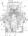
- the in Fig. 1 in longitudinal section and in simplified Represented drive device is particularly for driving a chain wheel of a tracked vehicle, e.g. B. a bulldozer or the like, suitable. It is a drive device that too is common under the name Turas drive.
- a sprocket not shown is non-rotatable connected to a rotating hub 1.
- the hub 1 has a non-rotatable connection on its circumference Variety of threaded holes 2, which are also not Pick up the bolts shown on the sprocket.
- the hub 1 is over two tapered roller bearings 3 on one stationary hub carrier 4 rotatably arranged.
- the tapered roller bearings are mounted in an O arrangement.
- the hub carrier 4 is firmly connected to the vehicle frame, which in detail not apparent from the drawing, but familiar to the expert is.
- a drive shaft is located in the stationary hub carrier 4 6 about a single bearing, especially one Tapered roller bearing 7, rotatably mounted.
- To the drive shaft 6 is followed by a connecting shaft 8.
- With the reference number 9 is the separation point between the drive shaft 6 and the connecting shaft 8 marked.
- the drive shaft 6 is supported on the one side in a floating manner at its free end - lying on the left in the drawing - with an inner central wheel 10 (sun) of a planetary gear 11 rotatably connected.
- the inner central wheel 10 can as in the present case, in one piece with the drive shaft 6 be made.
- the inner central wheel 10 is in constant meshing with planet gears 12, of which one is pictured.
- the planet gears 12 are on roller bearings 13 rotatable on a web 14 of the planetary gear 11 stored.
- the web 14 is also part of a final drive housing 15, which is tightly screwed to the hub 1 and which surrounds the planetary gear 11.
- the planet gears 12 are also in constant mesh with a stationary outer central gear 16 (ring gear) of the planetary gear 11.
- the outer central gear 16 is on the hub carrier 4 in the area of a profile 17 rotatably pushed on and in the axial direction by a nut 18 the tapered roller bearings 3 against a shoulder of the hub carrier 4 countered.
- the drive device is completed by a hydraulic motor 26. It is essential for the drive device that this hydraulic motor consists of a slow-running radial piston motor.
- the swallowing volume of the radial piston engine is approximately 1,180 cm 3 . The maximum speed is approx. 310 1 / min.
- the brake valves are located on the hydraulic motor.
- the hydraulic circuit is open.
- a cylinder block 27 is via a driving profile 28 rotatably connected to the drive shaft 6.
- a driving profile 28 rotatably connected to the drive shaft 6.
- Analogously to this consists of a geometrically identical driving profile 29 a rotationally fixed connection between the cylinder block 27 and the connecting shaft 8.
- Piston 30 mounted radially movable. These are supported from rollers 31 on a stationary cam track 32. over A distributor 33 is used to supply or remove the hydraulic fluid.
- a housing 26 encloses the radial piston motor and, like the cam track 32, is with the hub carrier 4 screwed. For this purpose, there are several in the hub carrier 4 Threaded holes 35 are provided.
- the connecting shaft 8 is axially displaceable. On the one hand, it is under the action of a compression spring 36 and on the other hand a force acts on them from is dependent on a pressure in a pressure chamber 37 prevails. In the drawn (left) end position of the connecting shaft 8 is the pressure prevailing in the pressure chamber 37 high so that a positive locking brake 38 is opened. In the other Case is this form-locking brake 38 by the force the compression spring 36 closed. The positive locking brake 38 acts as a parking brake when the vehicle is stationary.
- the Turas drive explained with a slow running Radial piston motor and a single-stage planetary gear enables the drive of a chain wheel at a highest possible translation.
- the Turas drive builds regarding of space requirements - based on the hub carrier 4 - approximately symmetrical. This means that on the one hand Side of the hydraulic motor 26 flanged and on the other Side the hub 1 together with the planetary gear 11 can be driven in rotation is arranged.
- the drive shaft 6 forms the drive connection between the radial piston motor and the planetary gear 11.
- a major advantage of this Connection is that the diameter of the drive shaft 6 and the hub carrier 4 in the area of this connection can be kept small. As a result, the Diameter of the tapered roller bearings 3 are also small.
- the radial dimensions of the mechanical seal are also 21 small. Because of the peripheral speeds the prevailing diameter ratios and the relative low speed levels also relatively low are, there is a reliable seal with a high lifespan.
- the drive device is compact and is also characterized by great smoothness.
- the planetary gear can be with straight or helical teeth Gears work.
- an additional seal on the drive shaft 6 39 for example a radial shaft seal, run.
- this drive device the web 14 is not part of the final drive housing 15. Rather, the outer central wheel is 16th as an output member of the planetary gear 40 part of the Hub 1.
- the final drive housing 15 is accordingly by the Hub 1 and an additional cover 41 are formed.
- This modified embodiment can then in particular Be used when the output speed level is so low that the maximum possible Translation (as in the embodiment of FIG. 1) can be dispensed with.
Landscapes
- Engineering & Computer Science (AREA)
- Chemical & Material Sciences (AREA)
- Combustion & Propulsion (AREA)
- Transportation (AREA)
- Mechanical Engineering (AREA)
- Retarders (AREA)
- Devices For Conveying Motion By Means Of Endless Flexible Members (AREA)
- Arrangement Or Mounting Of Propulsion Units For Vehicles (AREA)
- Arrangement And Driving Of Transmission Devices (AREA)
- Automatic Cycles, And Cycles In General (AREA)
- Valve-Gear Or Valve Arrangements (AREA)
Abstract
Description
Die Erfindung bezieht sich auf eine Antriebsvorrichtung für Arbeitsmaschinen, insbesondere für Kettenfahrzeuge, wie z. B. Planierraupen oder dergleichen.The invention relates to a drive device for work machines, especially for tracked vehicles, such as B. bulldozers or the like.
Dem Stand der Technik sind vielfältige Ausgestaltungen eines Turasantriebes als bekannt zu entnehmen. Bei diesen Antriebsvorrichtungen treibt ein Hydraulikmotor über ein Planetengetriebe ein Kettenrad an. Die Antriebsvorrichtung soll, insbesondere in axialer Richtung, geringe Abmessungen aufweisen, so daß sie nicht über die Breite einer Gleiskette, z. B. eines Raupenbaggers, hinausragt. Das Planetengetriebe muß eine ausreichend große Übersetzung aufweisen, damit ein niedriges Drehzahlniveau am Kettenrad erreicht wird. Die Antriebsvorrichtung muß mit einer Bremse versehen sein, damit bei Stillstand des Hydraulikmotors der Abtrieb festgebremst wird. Da die Antriebsvorrichtung auch unter extremen äußeren Bedingungen eingesetzt wird, muß für eine Zuverlässige Abdichtung bei einer hohen Lebensdauer gesorgt werden. Schließlich soll die Antriebsvorrichtung montage- und wartungsfreundlich sein. Im Hinblick auf die Herstellkosten muß die Anzahl der Bauteile der Antriebsvorrichtung möglichst klein sein.Various configurations are available in the state of the art a Turas drive as known. With these Drive devices drive a hydraulic motor over Planetary gear on a sprocket. The drive device should, especially in the axial direction, small dimensions have so that they are not the width of a caterpillar, e.g. B. a crawler excavator, protrudes. The planetary gear must have a sufficiently large translation, thus achieving a low speed level on the chain wheel becomes. The drive device must be equipped with a brake be so that the output when the hydraulic motor is at a standstill is braked. Since the drive device also under extreme external conditions must be used for a Reliable sealing with a long service life ensured become. Finally, the drive device should be assembled and be easy to maintain. In terms of manufacturing costs must be the number of components of the drive device be as small as possible.
Mit den bekannten Antriebsvorrichtungen sind die vorstehend erwähnten Forderungen nicht zu erfüllen. Wenn der Hydraulikmotor beispielsweise als Axialkolbenmaschine in Schrägscheibenbauweise ausgebildet ist, ist eine axial kurze Bauweise nur dann zu erreichen, wenn diese Axialkolbenmaschine in den Nabenträger integriert wird. Beispiele hierzu finden sich in der DE-A 27 44 936, DE-A 28 31 458 und der DE-A 42 35 697. In der Regel liegen die Drehzahlen des Hydraulikmotors so hoch, daß ein mehrstufiges Planetengetriebe verwendet werden muß. Diese Mehrstufigkeit erhöht zumeist die axiale Baulänge der Antriebsvorrichtung, so daß der mit der Integration des Hydraulikmotors in den Nabenträger erreichte Vorteil zumindest teilweise wieder aufgezehrt wird. Ein im Nabenträger integrierter Hydraulikmotor hat zur Folge, daß für die Lagerung der Nabe auf dem Nabenträger groß dimensionierte Lager verwendet werden müssen. Zu diesem Nachteil tritt ein weiterer hinzu: Da die Nahe gegenüber dem Nabenträger abgedichtet werden muß, sind Dichtungen mit ebenfalls großen Durchmessern erforderlich. Diese Umstände wirken kostensteigernd. Durch die relativ hohen Umfangsgeschwindigkeiten leidet ferner die Lebensdauer der Dichtung.With the known drive devices are the above not to meet the requirements mentioned. If the Hydraulic motor for example as an axial piston machine in Swashplate design is an axially short Construction can only be achieved if this axial piston machine is integrated into the hub carrier. Examples for this can be found in DE-A 27 44 936, DE-A 28 31 458 and DE-A 42 35 697. As a rule, the speeds are of the hydraulic motor so high that a multi-stage planetary gear must be used. This multilevel increases mostly the axial length of the drive device, so that the one with the integration of the hydraulic motor in the hub carrier achieved advantage at least partially consumed again becomes. A hydraulic motor integrated in the hub carrier has the consequence that for the storage of the hub on the hub carrier large-sized bearings must be used. Another disadvantage is added to this disadvantage: since the Nahe must be sealed against the hub carrier, are Seals with large diameters are also required. These circumstances increase costs. By the relative high peripheral speeds also affect the service life the seal.
Aus der US-A 4,271,725 ist ferner ein Radantrieb für Arbeitsmaschinen, insbesondere für Kettenfahrzeuge, bekannt, welcher aus einem Hydraulikmotor, nämlich einem Axialkolbenmotor in Schrägscheibenbauweise, besteht. Dieser treibt über eine Antriebswelle ein inneres Zentralrad eines mehrstufigen Planetengetriebes an, dessen Abtriebsglied mit einer Nabe, die auf einem stationär angeordneten Nabenträger gelagert ist, drehfest verbunden ist. Der Hydraulikmotor ist dabei, in Fahrzeuglängsrichtung gesehen, auf einer Seite des Nabenträgers angeflanscht, während auf der anderen Seite des Nabenträgers das mehrstufige Planetengetriebe und die Nahe angeordnet sind.From US-A 4,271,725 is also a wheel drive for Known machines, especially for tracked vehicles, which from a hydraulic motor, namely one Axial piston motor in swash plate design. This drives an inner central wheel of a drive shaft multi-stage planetary gear, the output member with a hub on a stationary hub carrier is stored, is rotatably connected. The hydraulic motor is here, seen in the vehicle longitudinal direction, on a Flanged on one side of the hub carrier while on the other The multi-stage planetary gear and the near are arranged.
Obwohl Radialkolbenmotoren dem Fachmann schon lange bekannt sind (vergleiche beispielsweise die DE-A 15 28 519 sowie die DE-A 22 55 239), werden sie bis heute in Kombination mit einer Bremse und einem Planetengetriebe nicht als Turasantriebe für Kettenfahrzeuge eingesetzt. Although radial piston motors have been around for a long time are known (compare, for example, DE-A 15 28 519 and DE-A 22 55 239), they are still used in combination with a brake and a planetary gear not as Turas drives used for tracked vehicles.
Der vorliegenden Erfindung liegt die Aufgabe zugrunde, eine Antriebsvorrichtung für den Einsatz in Kettenfahrzeugen zu schaffen, die sich insbesondere durch eine in der Herstellung preiswerte, kompakte sowie montage-, wartungsfreundliche und zuverlässige Bauweise auszeichnet.The present invention is based on the object a drive device for use in tracked vehicles to create, which in particular by one in the Manufacture of inexpensive, compact and easy to install and maintain and reliable design.
Die der Erfindung zugrunde liegende Aufgabe wird durch eine Antriebsvorrichtung gelöst, die die Merkmale des Hauptanspruches aufweist.The object underlying the invention is achieved by solved a drive device that the characteristics of Main claim.
Gegenüber den bekannten Turasantrieben überrascht die erfindungsgemäße Lösung durch eine außerordentlich einfache Bauweise. Der langsam laufende Radialkolbenmotor arbeitet auf einem Drehzahlniveau, der ein mehrstufiges Planetengetriebe nicht mehr erforderlich macht. Der Radiakolbenmotor ist daher mit einem einstufigen Planetengetriebe verbunden. Zudem besteht dieser Motor systembedingt aus relativ wenigen Bauteilen. Er baut in Axialrichtung kompakt, so daß er auf einer Seite des Nabenträgers direkt angeflanscht werden kann. Eine Antriebswelle verbindet den Zylinderblock des Radialkolbenmotors mit dem Planetengetriebe, dessen Abtriebsglied mit der Nabe drehfest verbunden ist. Compared to the well-known Turas drives, the solution according to the invention by an extremely simple Construction. The slow-running radial piston motor works at a speed level that is a multi-stage planetary gear no longer required. The radial piston engine is therefore connected to a single-stage planetary gear. Due to the system, this engine also consists of relatively few Components. It builds compact in the axial direction, so that it flange-mounted directly on one side of the hub carrier can. A drive shaft connects the cylinder block of the Radial piston motor with the planetary gear, its output member is rotatably connected to the hub.
Vorteilhafte Ausgestaltungen der erfindungsgemäßen Antriebsvorrichtung sind den Ansprüchen 2 bis 5 zu entnehmen.Advantageous embodiments of the invention Drive device can be found in claims 2 to 5.
Weitere, für die Erfindung wesentliche Merkmale sowie die hieraus resultierenden Vorteile sind der nachfolgenden Erläuterung zweier Ausführungsbeispiele zu entnehmen. Es zeigen:
- Fig. 1
- eine erste Ausführungsform einer Antriebsvorrichtung in vereinfachter Darstellung, insbesondere für ein Kettenfahrzeug, und
- Fig. 2
- eine weitere Ausführungsform, die insbesondere in der Gestaltung des Endabtriebs gegenüber der Anordnung nach Fig. 1 abweicht.
- Fig. 1
- a first embodiment of a drive device in a simplified representation, in particular for a tracked vehicle, and
- Fig. 2
- a further embodiment, which differs in particular in the design of the final drive compared to the arrangement according to FIG. 1.
Die in Fig. 1 im Längsschnitt und in vereinfachter Darstellung wiedergegebene Antriebsvorrichtung ist insbesondere für den Antrieb eines Kettenrades eines Kettenfahrzeuges, z. B. einer Planierraupe oder dergleichen, geeignet. Es handelt sich um eine Antriebsvorrichtung, die auch unter der Bezeichnung Turasantrieb geläufig ist.The in Fig. 1 in longitudinal section and in simplified Represented drive device is particularly for driving a chain wheel of a tracked vehicle, e.g. B. a bulldozer or the like, suitable. It is a drive device that too is common under the name Turas drive.
Ein selbst nicht abgebildetes Kettenrad ist drehfest
mit einer rotierend angeordneten Nabe 1 verbunden. Für die
drehfeste Verbindung weist die Nabe 1 an ihrem Umfang eine
Vielzahl von Gewindebohrungen 2 auf, die ebenfalls nicht
gezeigte Schraubenbolzen des Kettenrades aufnehmen.A sprocket not shown is non-rotatable
connected to a rotating
Die Nabe 1 ist über zwei Kegelrollenlager 3 auf einem
stationären Nabenträger 4 drehbar angeordnet. Die Kegelrollenlager
sind in O-Anordnung montiert. Der Nabenträger 4
ist mit dem Fahrzeugrahmen fest verbunden, was im einzelnen
der Zeichnung nicht zu entnehmen, jedoch dem Fachmann geläufig
ist. Für die feste Verbindung des Nabenträgers 4 mit
dem Fahrzeugrahmen sind ebenfalls mehrere Gewindebohrungen
5 am Umfang des Nabenträgers 4 verteilt angeordnet.The
Im stationär angeordneten Nabenträger 4 ist eine Antriebswelle
6 über ein einziges Lager, insbesondere ein
Kegelrollenlager 7, drehbar gelagert. An die Antriebswelle
6 schließt sich eine Verbindungswelle 8 an. Mit der Bezugsziffer
9 ist die Trennstelle zwischen der Antriebswelle
6 und der Verbindungswelle 8 gekennzeichnet.A drive shaft is located in the
Die einseitig fliegend gelagerte Antriebswelle 6 ist
an ihrem freien Ende - in der Zeichnung links liegend - mit
einem inneren Zentralrad 10 (Sonne) eines Planetengetriebes
11 drehfest verbunden. Das innere Zentralrad 10 kann,
wie im vorliegenden Fall, einstückig mit der Antriebswelle
6 gefertigt sein. Das innere Zentralrad 10 steht in
ständigem Zahneingriff mit Planetenrädern 12, von denen
eines abgebildet ist. Die Planetenräder 12 sind über Wälzlager
13 auf einem Steg 14 des Planetengetriebes 11 drehbar
gelagert. Der Steg 14 ist zudem Bestandteil eines Endabtriebsgehäuses
15, das mit der Nabe 1 dicht und fest verschraubt
ist und welches das Planetengetriebe 11 umschließt. The
Die Planetenräder 12 stehen ferner in ständigem Zahneingriff
mit einem stationären äußeren Zentralrad 16 (Hohlrad)
des Planetengetriebes 11. Das äußere Zentralrad 16 ist
auf den Nabenträger 4 im Bereich eines Profiles 17 drehfest
aufgeschoben und in Axialrichtung durch eine Mutter 18 über
die Kegelrollenlager 3 gegen eine Schulter des Nabenträgers
4 gekontert.The
Da die Nabe 1 gegenüber dem stationären Nabenträger 4
rotiert, stellt sich zwischen diesen Bauteilen ein radialer
Spalt 20 ein. Da das Endabtriebsgehäuse 15 zumindest teilweise
mit Schmier- und Kühlöl befüllt ist, muß eine geeignete
Dichtung vorhanden sein, die das Kühl- und Schmieröl
zurückhält bzw. die den Innenraum des Endabtriebsgehäuses
vor äußeren Einflüssen schützt. Diese Aufgaben übernimmt
eine Gleitringdichtung 21. Diese Gleitringdichtung 21 bekannter
Bauart besteht aus einem rotierenden Gleitring 22
und einem in eine Ausdrehung der Nabe 1 eingesetzten ersten
Dichtring 23 sowie einem stationären Gegenring 24 und einem
in eine Ausnehmung des Nabenträgers 4 eingelegten zweiten
Dichtring 25. Aus der Zeichnung geht hervor, daß die Gleitringdichtung
21 einen wirksamen Durchmesser aufweist, der
nur geringfügig größer ist als der Außendurchmesser der
Kegelrollenlager 3.Since the
Die Antriebsvorrichtung wird durch einen Hydraulikmotor
26 vervollständigt. Für die Antriebsvorrichtung ist
wesentlich, daß dieser Hydraulikmotor aus einem langsam
laufenden Radialkolbenmotor besteht. Das Schluckvolumen des
Radialkolbenmotors beträgt etwa 1 180 cm3. Die maximale
Drehzahl liegt bei ca. 310 1/min. Der Hydraulikmotor ist
schaltbar, wobei das Verhältnis der Schluckvolumina
Ein Zylinderblock 27 ist über ein Mitnahmeprofil 28
drehfest mit der Antriebswelle 6 verbunden. Analog hierzu
besteht über ein geometrisch gleich ausgebildetes Mitnahmeprofil
29 eine drehfeste Verbindung zwischen dem Zylinderblock
27 und der Verbindungswelle 8.A
In bekannter Weise sind im Zylinderblock 27 mehrere
Kolben 30 radial beweglich gelagert. Diese stützen sich
über Rollen 31 an einer stationären Nockenbahn 32 ab. Über
einen Verteiler 33 erfolgt die Zu- bzw. Abfuhr der Hydraulikflüssigkeit.
Ein Gehäuse 26 umschließt den Radialkolbenmotor
und ist, ebenso wie die Nockenbahn 32, mit dem Nabenträger
4 verschraubt. Hierzu sind im Nabenträger 4 mehrere
Gewindebohrungen 35 vorgesehen.In a known manner, there are several in the
Die Verbindungswelle 8 ist axial verschieblich angeordnet.
Sie steht einerseits unter der Wirkung einer Druckfeder
36 und andererseits wirkt auf sie eine Kraft, die von
einem Druck abhängig ist, der in einem Druckraum 37
herrscht. In der gezeichneten (linken) Endlage der Verbindungswelle
8 ist der im Druckraum 37 herrschende Druck
hoch, so daß eine Formschlußbremse 38 geöffnet ist. Im anderen
Fall ist diese Formschlußbremse 38 durch die Kraft
der Druckfeder 36 geschlossen. Die Formschlußbremse 38
wirkt als Feststellbremse bei Stillstand des Fahrzeuges.The connecting
Der erläuterte Turasantrieb mit einem langsam laufenden
Radialkolbenmotor und einem einstufigen Planetengetriebe
ermöglicht den Antrieb eines Kettenrades bei einer
höchstmöglichen Übersetzung. Der Turasantrieb baut hinsichtlich
des Raumbedarfes - bezogen auf den Nabenträger
4 - etwa symmetrisch. Dies bedeutet, daß auf der einen
Seite der Hydraulikmotor 26 angeflanscht und auf der anderen
Seite die Nabe 1 mitsamt dem Planetengetriebe 11 drehantreibbar
angeordnet ist. Die Antriebswelle 6 bildet die
triebliche Verbindung zwischen dem Radialkolbenmotor und
dem Planetengetriebe 11. Ein wesentlicher Vorteil dieser
Verbindung besteht darin, daß die Durchmesser der Antriebswelle
6 und des Nabenträgers 4 im Bereich dieser Verbindung
klein gehalten werden können. Hieraus resultiert, daß die
Durchmesser der Kegelrollenlager 3 ebenfalls klein sind.
Demzufolge sind auch die radialen Abmessungen der Gleitringdichtung
21 klein. Da die Umfangsgeschwindigkeiten wegen
der herrschenden Durchmesserverhältnisse und des relativ
niedrigen Drehzahlniveaus ebenfalls relativ niedrig
sind, ergibt sich eine zuverlässige Abdichtung bei einer
hohen Lebensdauer. Zudem baut die Antriebsvorrichtung kompakt
und zeichnet sich zusätzlich durch große Laufruhe aus.
Das Planetengetriebe kann mit gerad- oder Schrägverzahnten
Zahnrädern arbeiten.The Turas drive explained with a slow running
Radial piston motor and a single-stage planetary gear
enables the drive of a chain wheel at a
highest possible translation. The Turas drive builds regarding
of space requirements - based on the hub carrier
4 - approximately symmetrical. This means that on the one hand
Side of the
Der in Fig. 2 ebenfalls in vereinfachter Darstellung wiedergegebene Längsschnitt eines Turasantriebes weist prinzipielle Gemeinsamheiten zur Antriebsvorrichtung nach Fig. 1 auf. Gleiche Bauteile sind daher mit gleichen Bezugsziffern versehen.The also in Fig. 2 in a simplified representation reproduced longitudinal section of a Turas drive has basic similarities to the drive device Fig. 1 on. The same components are therefore with the same reference numbers Mistake.
Wenn mit getrennten Ölhaushalten gearbeitet werden
soll, kann auf der Antriebswelle 6 eine zusätzliche Dichtung
39, beispielsweise ein Radialwellendichtring, laufen.
Gegenüber dem oben erläuterten Ausführungsbeispiel besteht
ein wesentlicher Unterschied darin, daß der Steg 14 des
Planetengetriebes 40 über das Profil 17 drehfest mit dem
Nabenträger 4 verbunden ist. Demzufolge ist bei dieser Antriebsvorrichtung
der Steg 14 kein Bestandteil des Endabtriebsgehäuses
15. Vielmehr ist das äußere Zentralrad 16
als Abtriebsglied des Planetengetriebes 40 Bestandteil der
Nabe 1. Das Endabtriebsgehäuse 15 wird demnach durch die
Nabe 1 und einen zusätzlichen Deckel 41 gebildet. Diese
abgewandelte Ausführungsform kann insbesondere dann mit
Vorteil eingesetzt werden, wenn das abtriebsseitige Drehzahlniveau
so niedrig liegt, daß auf die maximal mögliche
Übersetzung (wie bei dem Ausführungsbeispiel nach Fig. 1)
verzichtet werden kann. When working with separate oil budgets
should, an additional seal on the
- 11
- Nabehub
- 22nd
- GewindebohrungTapped hole
- 33rd
- KegelrollenlagerTapered roller bearings
- 44th
- NabenträgerHub carrier
- 55
- GewindebohrungTapped hole
- 66
- Antriebswelledrive shaft
- 77
- KegelrollenlagerTapered roller bearings
- 88th
- VerbindungswelleConnecting shaft
- 99
- TrennstelleSeparation point
- 1010th
- inneres Zentralradinner central wheel
- 1111
- PlanetengetriebePlanetary gear
- 1212th
- PlanetenradPlanet gear
- 1313
- Wälzlagerroller bearing
- 1414
- Stegweb
- 1515
- EndabtriebsgehäuseFinal drive housing
- 1616
- äußeres Zentralradouter central wheel
- 1717th
- Profilprofile
- 1818th
- Muttermother
- 1919th
- Schultershoulder
- 2020th
- Spaltgap
- 2121
- GleitringdichtungMechanical seal
- 2222
- rotierender Gleitringrotating slide ring
- 2323
- DichtringSealing ring
- 2424th
- stationärer Gegenringstationary counter ring
- 2525th
- DichtringSealing ring
- 2626
- HydraulikmotorHydraulic motor
- 2727
- ZylinderblockCylinder block
- 2828
- MitnahmeprofilTake-away profile
- 2929
- MitnahmeprofilTake-away profile
- 3030th
- Kolbenpiston
- 3131
- Rollerole
- 3232
- Nockenbahn Cam track
- 3333
- VerteilerDistributor
- 3434
- Gehäusecasing
- 3535
- GewindebohrungTapped hole
- 3636
- DruckfederCompression spring
- 3737
- DruckraumPressure room
- 3838
- FormschlußbremsePositive locking brake
- 3939
- Dichtungpoetry
- 4040
- PlanetengetriebePlanetary gear
- 4141
- Deckelcover
Claims (5)
- Wheel drive for working machines, in particular for tracked vehicles, consisting of a hydraulic motor (26) which drives an inner central wheel (10) of a planetary gear unit (11, 40) via a drive shaft (6) and whose output member, which is formed, for example, by an arm (14) or an outer central wheel (16), is non-rotatably connected to a hub (1) mounted on a stationary hub carrier (4), and, viewed in the longitudinal direction of the vehicle, the hydraulic motor (26) is flange-mounted on one side of the hub carrier (4), while the planetary gear unit (11, 40) and the hub (1) are disposed on the other side of the hub carrier (4), and that a slide ring seal (21) is disposed between the hub carrier (4) and the hub (1), characterised in that the drive shaft (6) is mounted in cantilever fashion in the hub carrier (4), and the hydraulic motor (26) is in the form of a slow-running radial piston motor and the planetary gear unit (11, 40) is of single-stage construction.
- Drive device according to claim 1, characterised in that the outer central wheel (16) is non-rotatably connected to the hub carrier (4), and the output member is formed by the arm (14) of the planetary gear unit (11), which arm is rigidly connected to the hub (1) via an end output housing (15).
- Drive device according to claim 1, characterised in that the arm (14) of the planetary gear system (40) is non-rotatably connected to the hub carrier (4), while the output member is formed by the outer central wheel (16) non-rotatably connected to the hub (1).
- Drive device according to claim 1, characterised in that the slide ring seal (21) consists of a rotating slide ring (22) and a first sealing ring (23), which is inserted in a bore in the hub (1), as well as of a stationary counter ring (24) and a second sealing ring (25), which is placed in a recess in the hub carrier (4).
- Drive device according to claim 1, characterised in that a positive-locking brake (38) is associated with the hydraulic motor (26).
Applications Claiming Priority (3)
| Application Number | Priority Date | Filing Date | Title |
|---|---|---|---|
| DE19503477A DE19503477A1 (en) | 1995-02-03 | 1995-02-03 | Drive device, in particular wheel drive for tracked vehicles |
| DE19503477 | 1995-02-03 | ||
| PCT/EP1996/000331 WO1996023670A1 (en) | 1995-02-03 | 1996-01-27 | Drive device, in particular a wheel drive for tracked vehicles |
Publications (2)
| Publication Number | Publication Date |
|---|---|
| EP0807030A1 EP0807030A1 (en) | 1997-11-19 |
| EP0807030B1 true EP0807030B1 (en) | 1999-03-31 |
Family
ID=7753063
Family Applications (1)
| Application Number | Title | Priority Date | Filing Date |
|---|---|---|---|
| EP96902931A Expired - Lifetime EP0807030B1 (en) | 1995-02-03 | 1996-01-27 | Drive device, in particular a wheel drive for tracked vehicles |
Country Status (9)
| Country | Link |
|---|---|
| US (1) | US5820506A (en) |
| EP (1) | EP0807030B1 (en) |
| JP (1) | JPH11500381A (en) |
| KR (1) | KR100465422B1 (en) |
| CN (1) | CN1086347C (en) |
| AT (1) | ATE178278T1 (en) |
| BR (1) | BR9607436A (en) |
| DE (2) | DE19503477A1 (en) |
| WO (1) | WO1996023670A1 (en) |
Cited By (2)
| Publication number | Priority date | Publication date | Assignee | Title |
|---|---|---|---|---|
| US6742618B2 (en) | 2000-03-07 | 2004-06-01 | Arctic Cat, Inc. | Snowmobile planetary drive system |
| US6907951B2 (en) | 2000-03-07 | 2005-06-21 | Arctic Cat, Inc. | Snowmobile planetary drive system |
Families Citing this family (19)
| Publication number | Priority date | Publication date | Assignee | Title |
|---|---|---|---|---|
| DE19637570A1 (en) | 1996-09-14 | 1998-03-19 | Zahnradfabrik Friedrichshafen | Hydrostatic-mechanical wheel drive |
| DE19637590A1 (en) * | 1996-09-14 | 1998-03-19 | Zahnradfabrik Friedrichshafen | Hydrostatic-mechanical drive unit for refuse disposal vehicles, fire engines and other heavy vehicles |
| FR2760048B1 (en) * | 1997-02-27 | 2001-11-16 | Poclain Hydraulics Sa | HYDRAULIC DRIVE FOR CONSTRUCTION VEHICLE |
| KR100493536B1 (en) * | 1997-05-26 | 2005-11-28 | 오꾸보 하구루마 고교 가부시키가이샤 | Reduction gear device |
| DE19814273A1 (en) * | 1998-03-31 | 1999-10-07 | Zahnradfabrik Friedrichshafen | Hydrostatic mechanical drive |
| DE19837487C2 (en) * | 1998-08-12 | 2002-07-18 | Lohmann & Stolterfoht Gmbh | sealing arrangement |
| DE19845494C2 (en) † | 1998-10-02 | 2000-07-27 | Krauss Maffei Wegmann Gmbh & C | Tracked vehicle |
| DE19903563A1 (en) * | 1999-01-29 | 2000-08-03 | Linde Ag | Hydrostatic motor unit for working machines such as mobile excavators, for example, has co-axially disposed centrally ported constant displacement radial piston motor and variable displacement axial piston swashplate motor |
| AU2001273656A1 (en) * | 2000-06-30 | 2002-01-14 | Llewellan Anderson | Improved rolling cutter lubrication arrangement |
| FR2813652B1 (en) * | 2000-09-07 | 2003-06-20 | Poclain Hydraulics Ind | DRIVE DEVICE COMPRISING A HYDRAULIC MOTOR AND A REDUCER |
| DE102006023577A1 (en) * | 2006-05-19 | 2007-11-22 | Jungheinrich Ag | Wheel hub drive for industrial trucks |
| DE102006043290A1 (en) * | 2006-09-14 | 2008-03-27 | Zf Friedrichshafen Ag | Hydrostatic-mechanical transmission |
| DE102006058076A1 (en) * | 2006-12-07 | 2008-06-19 | Zf Friedrichshafen Ag | Hydraulic radial piston motor |
| DE102012204795A1 (en) * | 2012-03-26 | 2013-09-26 | Schaeffler Technologies AG & Co. KG | Wheel hub motor with equipotential bonding |
| FR3030381B1 (en) * | 2014-12-19 | 2018-10-19 | Eugene Albert Laurent | HYDRAULIC MOTOR FOR VEHICLE WHEEL |
| FR3030382B1 (en) * | 2014-12-23 | 2017-01-13 | Poclain Hydraulics Ind | HYDRAULIC TORQUE MOTOR |
| JP6408425B2 (en) | 2015-05-07 | 2018-10-17 | 株式会社小松製作所 | Power transmission device and motor grader |
| CN112498086B (en) * | 2020-11-30 | 2024-07-05 | 烟台大学 | Driving axle with hub motor |
| FR3136520B1 (en) * | 2022-06-13 | 2024-08-23 | Poclain Hydraulics Ind | Improved hydraulic pump for high speed drive |
Family Cites Families (16)
| Publication number | Priority date | Publication date | Assignee | Title |
|---|---|---|---|---|
| US2155198A (en) * | 1934-05-05 | 1939-04-18 | William E Lawrence | Variable speed gearing mechanism |
| HU164077B (en) * | 1970-09-28 | 1973-12-28 | ||
| US3865207A (en) * | 1971-04-23 | 1975-02-11 | Hyster Co | Hydraulic feed for wheel motors |
| US3749195A (en) * | 1971-05-03 | 1973-07-31 | Eaton Corp | Hydrostatic drive transmission assembly |
| AR205148A1 (en) * | 1971-11-11 | 1976-04-12 | Renold Ltd | MOTORIZED WHEEL UNIT |
| US3770075A (en) * | 1972-03-20 | 1973-11-06 | Eaton Corp | Free wheeling 2-speed motor wheel |
| US4040312A (en) * | 1974-10-29 | 1977-08-09 | Eaton Corporation | Planetary reduction drive unit |
| FR2379394A1 (en) * | 1977-02-04 | 1978-09-01 | Poclain Hydraulics Sa | DEVICE FOR FIXING AND DRIVING A VEHICLE MOVEMENT UNIT |
| JPS5449433A (en) * | 1977-09-28 | 1979-04-18 | Ebara Corp | Hydraulic motor unit for driving crawler |
| DE2744936A1 (en) * | 1977-10-06 | 1979-04-12 | Zahnradfabrik Friedrichshafen | SINGLE WHEEL DRIVE FOR WORK MACHINERY |
| DE2831458C2 (en) * | 1978-07-18 | 1983-03-24 | Zahnradfabrik Friedrichshafen Ag, 7990 Friedrichshafen | Wheel drive for work machines, in particular for tracked vehicles |
| FI73789C (en) * | 1983-12-07 | 1987-11-09 | Partek Ab | HYDRAULISK MOTOR. |
| US4649772A (en) * | 1985-07-05 | 1987-03-17 | Caterpillar Inc. | Planetary wheel drive assembly |
| DE4110161A1 (en) * | 1991-03-27 | 1992-10-01 | Man Nutzfahrzeuge Ag | DRIVE DEVICE FOR VEHICLES |
| DE4206086B4 (en) * | 1992-02-27 | 2004-04-22 | Linde Ag | Modular drive system |
| DE4235697A1 (en) * | 1992-09-23 | 1994-03-24 | Linde Ag | Hydromechanical drive set with incorporated epicyclic gear - which is mounted on journal, whose front side carries control face of hydraulic motor |
-
1995
- 1995-02-03 DE DE19503477A patent/DE19503477A1/en not_active Withdrawn
-
1996
- 1996-01-27 JP JP8523232A patent/JPH11500381A/en active Pending
- 1996-01-27 EP EP96902931A patent/EP0807030B1/en not_active Expired - Lifetime
- 1996-01-27 CN CN96191714A patent/CN1086347C/en not_active Expired - Fee Related
- 1996-01-27 DE DE59601556T patent/DE59601556D1/en not_active Expired - Lifetime
- 1996-01-27 WO PCT/EP1996/000331 patent/WO1996023670A1/en active IP Right Grant
- 1996-01-27 US US08/875,196 patent/US5820506A/en not_active Expired - Fee Related
- 1996-01-27 BR BR9607436A patent/BR9607436A/en not_active Application Discontinuation
- 1996-01-27 KR KR1019970705181A patent/KR100465422B1/en not_active IP Right Cessation
- 1996-01-27 AT AT96902931T patent/ATE178278T1/en not_active IP Right Cessation
Cited By (3)
| Publication number | Priority date | Publication date | Assignee | Title |
|---|---|---|---|---|
| US6742618B2 (en) | 2000-03-07 | 2004-06-01 | Arctic Cat, Inc. | Snowmobile planetary drive system |
| US6907951B2 (en) | 2000-03-07 | 2005-06-21 | Arctic Cat, Inc. | Snowmobile planetary drive system |
| US7063639B2 (en) | 2000-03-07 | 2006-06-20 | Arctic Cat Inc. | Snowmobile planetary drive system |
Also Published As
| Publication number | Publication date |
|---|---|
| DE19503477A1 (en) | 1996-08-08 |
| BR9607436A (en) | 1998-05-26 |
| JPH11500381A (en) | 1999-01-12 |
| CN1172455A (en) | 1998-02-04 |
| CN1086347C (en) | 2002-06-19 |
| US5820506A (en) | 1998-10-13 |
| KR100465422B1 (en) | 2005-05-17 |
| EP0807030A1 (en) | 1997-11-19 |
| WO1996023670A1 (en) | 1996-08-08 |
| DE59601556D1 (en) | 1999-05-06 |
| ATE178278T1 (en) | 1999-04-15 |
| KR19980701784A (en) | 1998-06-25 |
Similar Documents
| Publication | Publication Date | Title |
|---|---|---|
| EP0807030B1 (en) | Drive device, in particular a wheel drive for tracked vehicles | |
| DE69611313T2 (en) | Lubrication system for automotive transmissions | |
| EP1776525B1 (en) | Hydrostatic rotary cylinder engine | |
| DE19715278C2 (en) | Gear unit | |
| DE2831458C2 (en) | Wheel drive for work machines, in particular for tracked vehicles | |
| DE69321195T2 (en) | Oil lubrication system for intermediate axle gear | |
| DE60312776T2 (en) | Differential axle arrangement, in particular with a lubrication pump for a Zwischenachsdifferentialanordnung | |
| DE102005041579B4 (en) | Internal gear pump with filling piece | |
| DE2849994A1 (en) | ROTARY PISTON MACHINE | |
| DE19645650C1 (en) | Rock face cutting head | |
| EP1900971B1 (en) | Hydrostatic/mechanical transmission | |
| DE102014210774B4 (en) | Hydraulic drive with an adjustable hydraulic axial piston machine in dry-case design | |
| DE112022001054T5 (en) | Electric cylinder and working machine | |
| DE4206102C2 (en) | Hydromechanical transmission | |
| DE102018205862A1 (en) | Transmission, in particular for a single-wheel drive unit | |
| DE10325781B4 (en) | epicyclic gear | |
| DE3028022A1 (en) | ROTARY PISTON MACHINE DESIGNED AS A WHEEL DRIVE | |
| EP1900972B1 (en) | Hydrostatic mechanical transmission | |
| DE102005002858B4 (en) | Gear arrangement of a drive axle of a motor vehicle | |
| DE3307047A1 (en) | Unit comprising a pressure-medium piston motor and an epicyclic gearing | |
| DE3603773A1 (en) | Gear machine | |
| WO2020035344A1 (en) | Transmission, in particular for a single wheel drive unit | |
| DE102005044576A1 (en) | Internal gear pump | |
| DE102017209363A1 (en) | Final gear unit for a rail vehicle | |
| EP0475109A1 (en) | Internal-gear pump for hydraulic fluid |
Legal Events
| Date | Code | Title | Description |
|---|---|---|---|
| PUAI | Public reference made under article 153(3) epc to a published international application that has entered the european phase |
Free format text: ORIGINAL CODE: 0009012 |
|
| 17P | Request for examination filed |
Effective date: 19970702 |
|
| AK | Designated contracting states |
Kind code of ref document: A1 Designated state(s): AT BE DE FR GB IT |
|
| 17Q | First examination report despatched |
Effective date: 19971209 |
|
| GRAG | Despatch of communication of intention to grant |
Free format text: ORIGINAL CODE: EPIDOS AGRA |
|
| GRAG | Despatch of communication of intention to grant |
Free format text: ORIGINAL CODE: EPIDOS AGRA |
|
| GRAH | Despatch of communication of intention to grant a patent |
Free format text: ORIGINAL CODE: EPIDOS IGRA |
|
| GRAH | Despatch of communication of intention to grant a patent |
Free format text: ORIGINAL CODE: EPIDOS IGRA |
|
| GRAA | (expected) grant |
Free format text: ORIGINAL CODE: 0009210 |
|
| AK | Designated contracting states |
Kind code of ref document: B1 Designated state(s): AT BE DE FR GB IT |
|
| REF | Corresponds to: |
Ref document number: 178278 Country of ref document: AT Date of ref document: 19990415 Kind code of ref document: T |
|
| GBT | Gb: translation of ep patent filed (gb section 77(6)(a)/1977) |
Effective date: 19990401 |
|
| REF | Corresponds to: |
Ref document number: 59601556 Country of ref document: DE Date of ref document: 19990506 |
|
| ET | Fr: translation filed | ||
| PG25 | Lapsed in a contracting state [announced via postgrant information from national office to epo] |
Ref country code: AT Free format text: LAPSE BECAUSE OF NON-PAYMENT OF DUE FEES Effective date: 20000127 |
|
| PLBE | No opposition filed within time limit |
Free format text: ORIGINAL CODE: 0009261 |
|
| STAA | Information on the status of an ep patent application or granted ep patent |
Free format text: STATUS: NO OPPOSITION FILED WITHIN TIME LIMIT |
|
| 26N | No opposition filed | ||
| PGFP | Annual fee paid to national office [announced via postgrant information from national office to epo] |
Ref country code: BE Payment date: 20010123 Year of fee payment: 6 |
|
| REG | Reference to a national code |
Ref country code: GB Ref legal event code: IF02 |
|
| PG25 | Lapsed in a contracting state [announced via postgrant information from national office to epo] |
Ref country code: BE Free format text: LAPSE BECAUSE OF NON-PAYMENT OF DUE FEES Effective date: 20020131 |
|
| BERE | Be: lapsed |
Owner name: ZF FRIEDRICHSHAFEN A.G. Effective date: 20020131 |
|
| PGFP | Annual fee paid to national office [announced via postgrant information from national office to epo] |
Ref country code: GB Payment date: 20040121 Year of fee payment: 9 |
|
| PG25 | Lapsed in a contracting state [announced via postgrant information from national office to epo] |
Ref country code: GB Free format text: LAPSE BECAUSE OF NON-PAYMENT OF DUE FEES Effective date: 20050127 |
|
| GBPC | Gb: european patent ceased through non-payment of renewal fee |
Effective date: 20050127 |
|
| PGFP | Annual fee paid to national office [announced via postgrant information from national office to epo] |
Ref country code: IT Payment date: 20060131 Year of fee payment: 11 |
|
| PG25 | Lapsed in a contracting state [announced via postgrant information from national office to epo] |
Ref country code: IT Free format text: LAPSE BECAUSE OF NON-PAYMENT OF DUE FEES Effective date: 20070127 |
|
| PGFP | Annual fee paid to national office [announced via postgrant information from national office to epo] |
Ref country code: FR Payment date: 20100208 Year of fee payment: 15 |
|
| PGFP | Annual fee paid to national office [announced via postgrant information from national office to epo] |
Ref country code: DE Payment date: 20100121 Year of fee payment: 15 |
|
| REG | Reference to a national code |
Ref country code: FR Ref legal event code: ST Effective date: 20110930 |
|
| PG25 | Lapsed in a contracting state [announced via postgrant information from national office to epo] |
Ref country code: FR Free format text: LAPSE BECAUSE OF NON-PAYMENT OF DUE FEES Effective date: 20110131 |
|
| REG | Reference to a national code |
Ref country code: DE Ref legal event code: R119 Ref document number: 59601556 Country of ref document: DE Effective date: 20110802 |
|
| PG25 | Lapsed in a contracting state [announced via postgrant information from national office to epo] |
Ref country code: DE Free format text: LAPSE BECAUSE OF NON-PAYMENT OF DUE FEES Effective date: 20110802 |