EP0806379B1 - Dispositif pour la surveillance du serrage des boulons d'un élément de jonction de la courroie d'un élévateur à godets - Google Patents
Dispositif pour la surveillance du serrage des boulons d'un élément de jonction de la courroie d'un élévateur à godets Download PDFInfo
- Publication number
- EP0806379B1 EP0806379B1 EP97104114A EP97104114A EP0806379B1 EP 0806379 B1 EP0806379 B1 EP 0806379B1 EP 97104114 A EP97104114 A EP 97104114A EP 97104114 A EP97104114 A EP 97104114A EP 0806379 B1 EP0806379 B1 EP 0806379B1
- Authority
- EP
- European Patent Office
- Prior art keywords
- switching element
- switching
- oscillatory circuit
- disposed
- rest
- Prior art date
- Legal status (The legal status is an assumption and is not a legal conclusion. Google has not performed a legal analysis and makes no representation as to the accuracy of the status listed.)
- Expired - Lifetime
Links
- 238000012544 monitoring process Methods 0.000 title claims description 5
- 238000011156 evaluation Methods 0.000 claims description 11
- 239000003990 capacitor Substances 0.000 claims description 9
- 230000008859 change Effects 0.000 claims description 7
- 230000003534 oscillatory effect Effects 0.000 claims 20
- 239000000470 constituent Substances 0.000 claims 1
- 230000036316 preload Effects 0.000 description 21
- 230000005284 excitation Effects 0.000 description 6
- 238000012806 monitoring device Methods 0.000 description 6
- 238000006243 chemical reaction Methods 0.000 description 3
- 230000009467 reduction Effects 0.000 description 3
- 230000001960 triggered effect Effects 0.000 description 3
- XEEYBQQBJWHFJM-UHFFFAOYSA-N Iron Chemical group [Fe] XEEYBQQBJWHFJM-UHFFFAOYSA-N 0.000 description 2
- 238000013459 approach Methods 0.000 description 2
- 230000008878 coupling Effects 0.000 description 2
- 238000010168 coupling process Methods 0.000 description 2
- 238000005859 coupling reaction Methods 0.000 description 2
- 230000000694 effects Effects 0.000 description 2
- 238000004146 energy storage Methods 0.000 description 2
- 230000009471 action Effects 0.000 description 1
- 230000015556 catabolic process Effects 0.000 description 1
- 230000006835 compression Effects 0.000 description 1
- 238000007906 compression Methods 0.000 description 1
- 238000010586 diagram Methods 0.000 description 1
- 230000005684 electric field Effects 0.000 description 1
- 230000002996 emotional effect Effects 0.000 description 1
- 238000005259 measurement Methods 0.000 description 1
- 239000002184 metal Substances 0.000 description 1
- 229910052751 metal Inorganic materials 0.000 description 1
- 238000000034 method Methods 0.000 description 1
- 230000010355 oscillation Effects 0.000 description 1
- 230000035939 shock Effects 0.000 description 1
- 230000007704 transition Effects 0.000 description 1
Images
Classifications
-
- F—MECHANICAL ENGINEERING; LIGHTING; HEATING; WEAPONS; BLASTING
- F16—ENGINEERING ELEMENTS AND UNITS; GENERAL MEASURES FOR PRODUCING AND MAINTAINING EFFECTIVE FUNCTIONING OF MACHINES OR INSTALLATIONS; THERMAL INSULATION IN GENERAL
- F16G—BELTS, CABLES, OR ROPES, PREDOMINANTLY USED FOR DRIVING PURPOSES; CHAINS; FITTINGS PREDOMINANTLY USED THEREFOR
- F16G3/00—Belt fastenings, e.g. for conveyor belts
- F16G3/06—Belt fastenings, e.g. for conveyor belts with outwardly-bent, mutually-connected belt ends
Definitions
- the invention relates to a device for monitoring the Screw pre-tensioning of a screwed clamping device for connecting the belt ends of a bucket elevator belt
- Belt ends are clamped between clamping pieces that are connected to each other with preloaded screws, with one arranged on the screw connection to be monitored Switching part, which is in normal operating state, So if the preload is sufficiently large Screw connection, is in a rest position, and which occurs when the value falls below a specified value Bias limit automatically in a warning or Switch position triggering switch-off signal moved.
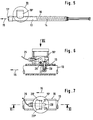
- Monitoring device consists of a switching part arranged transversely to the longitudinal direction of the belt on the clamping device and guided bolt by a compression spring is applied and in normal operating condition against the force generated by the spring from an abutment in its Rest position is held, in which its actuation end adjacent to the corresponding belt edge in Belt area is located.
- the abutment consists of one between a fitting and the screw connection to be monitored arranged disc that on a towards on the switching part protruding nose with the switching part in is positive engagement and this against the force the spring acting on the switching part in its rest position lasts as long as the due to the preload of the Screw connection generated frictional forces acting on the washer generate a torque greater than is the torque exerted by the switching part.
- the present invention is therefore based on the object to improve the known monitoring device so that if the pre-stressing limit is undershot a warning or shutdown signal by means of the switching part is triggered without contact, without it this requires actuation of a stationary switch.
- this object is achieved by that in the area of the switching part on the belt a passive first electrical resonant circuit and adjacent to the movement path the clamping device stationary from an AC power source second electric excited with constant frequency Resonant circuit is arranged, the current strength in the second resonant circuit when the two pass Resonant circuits has a setpoint if that Switching part is in its rest position; that this Switching part in its movement from its rest position its switching position the original switching state of the first resonant circuit automatically changed so that the existing reaction when passing the two resonant circuits of the first resonant circuit to the current in second resonant circuit compared to the retroactive effect in the original Switching state is changed; and that in second resonant circuit with an evaluation and control device connected ammeter is arranged, wherein the evaluation device each when passing the two Vibration circuits measured actual current with the target current compares in the normal operating state and the Control device generates a warning or shutdown signal, if the actual amperage is one predefined difference differs.
- a resonant circuit is known to mean one two electrical circuits having energy stores, which is capable of free oscillations of the current and the Execute voltage, the one energy storage for the electric field energy one capacitor and the other Energy storage for the magnetic field energy a coil is.
- each resonant circuit contains any losses, which are represented in an ohmic resistance can, but are not taken into account below, because they essentially for the subject matter of the invention are irrelevant.
- An electrical resonant circuit carries free vibrations always off when e.g. triggered by a shift shock and then left to itself You eat against him with alternating current, he leads (after a short Transition period) forced vibrations. Is in the excitation frequency is essentially equal to the natural frequency, this is called a resonance circuit or resonance mode.
- the excited second Resonant circuit is operated in resonance, and highly preferred further provided that the natural frequency of the passive first resonant circuit (at least) in one of the two positions of the switching part essentially on the Excitation frequency or the natural frequency of the excited second Resonant circuit is tuned, so also in resonance is operated.
- the current intensity that occurs sets the target current for the normal operating state represents the preload of the monitored screw connection still above the preload limit lies.
- the one supplied by the AC power source is preferred second resonant circuit designed as a series resonant circuit, whose coil and capacitor are connected in series, and the (passive) first resonant circuit as a parallel resonant circuit.
- the switching part can be a component of the first resonant circuit or with one Part of the first resonant circuit to be connected to the Moving the switching part from its rest position into its Switch position a detuning or a vote of cause two resonant circuits.
- the switching part For example, be the coil core of the first resonant circuit or be connected with this so that the coil core at Movement of the switching part from its rest position in its Switch position relative to the coil while changing the inductance of the first resonant circuit is moved.
- the switching part designed or arranged so that when it moves from its rest position into its Switch position the previously closed first resonant circuit opens or the previously opened first resonant circuit closes and thereby compared to the previous state of first resonant circuit - and at the same time in relation to the second resonant circuit - "out of tune".
- a switch of the first resonant circuit be arranged, which is actuated by the switching part will, if this from its rest position in its Switch position moves, with the switch either open or is closed.
- a line section of the first Resonant circuit be arranged by the switching part is severed when this comes from its rest position moved into its switch position.
- the inductances of the resonant circuits are preferred as rod-shaped coils, the coils of the two Oscillating circuits preferably essentially parallel to one another and continue to be arranged so that they are essentially when passing the two resonant circuits cover, where it continues to be particularly useful has pointed out when the coils are perpendicular to Longitudinal direction of the belt are arranged.
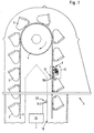
- Fig. 1 shows a schematic side view of the top Section of a bucket elevator designated as a whole with cups 2, each with the same pitch are attached to an endless belt 3 which around rotates two drums 4, of which only one in Fig. 1 Drum is recognizable.
- a drum 4 as a drive drum trained by a not shown Drive is drivable, and the drum other than Tensioning drum, by means of which the belt 3 is to be tensioned.
- the belt 3 is designated as 5 overall Clamping device made endless, the best of Fig. 2nd is recognizable.
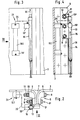
- the two end sections 3 ' of the belt 3 at right angles from the plane of the belt led out outside and between two made of metal Shaped pieces 6, 6 and a middle shaped wedge 7 are arranged and screwed with twelve screw connections 8, each consisting of a screw 9, a nut 10, one Lock nut 11 and washers exist.
- Both Screws 9 are expansion screws that the Assembly with a considerable preload, to release the belt end sections 3 'from the clamping device to prevent during operation.
- the preload that is initially applied becomes tightening the screw connections 8 to a predetermined preload repeated after a short period of operation (possibly several times).
- the clamping device 5 with a device for monitoring the Prestressing the screw connections 8, the one Warning or shutdown signal generated when the bias the screw connections 8 a predetermined preload limit falls below. Since it has been shown that the Preloading all screw connections 8 essentially drops evenly, it is sufficient if only a screw connection 8 '(see FIG. 4) is monitored as this is described in detail below. Be there pointed out that in Fig. 4 only three screw connections are shown, while the others are only are indicated by crosses.
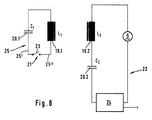
- a coil is located in the region of the switching part 13 on the belt 3 19.1 and a first electrical resonant circuit 21 having a capacitor 20.1 are arranged and adjacent to the endless movement path of the clamping device 5 rotating around the drums 4 during operation on the stationary bucket elevator housing 18, a second resonant circuit 22 containing a coil 19.2 and a capacitor 20.2 (see FIG. 8 ).
- the stationary second oscillating circuit 22 is fed by an alternating current source formed by a sine generator G with a frequency of 10 kHz, the coil 19.2 with an iron core having an inductance L 2 and the capacitor 20.2 with a capacitance C 2 being connected in series, while the coil 19.1, also provided with an iron core, with an inductance L 1 and the capacitor 20.1 with a capacitance C 1 of the first resonant circuit 21 are connected in parallel, the switch 23 shown in FIG. 8 in this resonant circuit 21 being closed in the normal operating state.
- the second resonant circuit 22 there is one designated 24 as a whole Contain measuring, evaluation and control device, among others has an ammeter with which the alternating current flow to measure in the active second resonant circuit 22 and to be forwarded to the evaluation device as a reference variable is.
- the natural frequencies of the two resonant circuits 21,22 are in the normal operating state (if that Switching part 13 is in its locked rest position) matched to the excitation frequency.
- the current intensity measured in the device 24 is due to the resulting coupling of the two resonant circuits 21, 22 each drops when the first arranged on the belt 3 Oscillating circuit 21 moves past second oscillating circuit 22 becomes. Is therefore contained in the device 24 Evaluation device when passing the first Oscillating circuit 21 provided clamping device 5 a corresponding change in the current is determined, so is this a sign of a proper operating condition, so that the operation can continue.
- the pre-tensioning limit is undershot on the monitored screw connection 8 ' Switching part 13 unlocked in the manner described moves from its rest position to its switch position, it changes the switching state of the first one Oscillating circuit 21 and thus its reaction on the Current in the second resonant circuit 22 when passing two resonant circuits 21, 22 by the first resonant circuit 21 opens so that the AC flow in the active second resonant circuit 22 as the clamping device passes 5 is practically no longer changed, the evaluation device so no significant change in AC flow in the second resonant circuit 22 determines more and then generates a warning or shutdown signal.
- the inductors L 1 and L 2 of the resonant circuits 21, 22 are designed as rod-shaped coils and (see FIG. 1) are arranged parallel to one another, specifically so that they overlap when passing without any lateral offset.
- the longitudinal extent of the two coils 19.1 and 19.2 is perpendicular to the running direction of the belt 3.
- the capacitors 20.1 and 20.2 are each in a housing 19 'of the relevant coil 19 integrated and in the Drawing not recognizable.
- the line section 25 containing the switch 23 of the first resonant circuit 21 is from the capacitor 20.1 or from the coil 19.1 two-wire to a socket-shaped approach 16 'of the guide 16 for the switching part 13, wherein the two wires 25 'and 25' 'within the approach 16 'each formed as an electrically conductive spring tongue are between which an electrically conductive connecting element 26 is arranged (namely held clamped), which together with a radial of the bolt-shaped Switching part 13 projecting outwards into a slot 27 the bushing-shaped guide 16 engaging pin 28 "Switch" 23 of the first resonant circuit 21 forms and of the pin 28 from its contact position shown in FIG.
- the evaluation device integrated in the device 24 programmed to issue a warning or shutdown signal only triggers if after a multiple (e.g. three times) passing the first resonant circuit 21 none at the second resonant circuit 22 in the second resonant circuit 22 Change in current has been found to ensure that the operation of the bucket elevator is not already interrupted due to a random incorrect measurement becomes.
- the Arrangement instead made for example be that the switch provided in the first resonant circuit 21 23 is open in the normal operating state, so that the second resonant circuit 22 when passing the first Oscillating circuit 21 in terms of the size of its alternating current flow remains essentially unaffected, and closed is when the switching part 13 from its Rest position moved to its switching position, so that at a corresponding resonance vote of the two Oscillating circuits 21, 22 in the closed state of the first Resonant circuit 21, the current in the stationary second Oscillating circuit 22 when passing the two oscillating circuits 21,22 is changed.
- the arrangement could be like this be taken that the first resonant circuit 21 during the Operation is always closed, so it is always functional Resonant circuit forms, however, the vote of the two resonant circuits 21, 22 through the switching part 13 is changed if this is from its rest position moved into its switching position, preferably such that in normal operating conditions there is a vote of the two natural frequencies, each one significant change in the size of the alternating current flow in the second resonant circuit 22 leads when the first Resonant circuit 21 moves past second resonant circuit 22, and a significant detuning of the resonance frequency of the first resonant circuit 21 takes place when that Switching part 13 moves into its switching position, so that the size of the alternating current flow in the second Vibration circuit 22 does not experience any significant change if the two resonant circuits 21, 22 pass each other.
Landscapes
- Engineering & Computer Science (AREA)
- General Engineering & Computer Science (AREA)
- Mechanical Engineering (AREA)
- Control Of Conveyors (AREA)
- Burglar Alarm Systems (AREA)
- Impression-Transfer Materials And Handling Thereof (AREA)
- Maintenance And Inspection Apparatuses For Elevators (AREA)
Claims (17)
- Dispositif pour surveiller la précontrainte de vissage d'un dispositif de serrage vissé (5) destiné à assembler les extrémités (3') d'une courroie d'élévateur à godets (3), comportant une partie de coupure (13) qui est agencée sur l'assemblage vissé (8'), qui se trouve dans une position de repos pour une précontrainte assez grande et qui se déplace automatiquement dans une position de coupure déclenchant un signal d'avertissement ou de coupure lorsque la précontrainte devient inférieure à une valeur limite de précontrainte prédéterminée, caractérisé en ce qu'un premier circuit électrique oscillant (21) avec une fréquence de résonance prédéterminée est agencé sur la courroie (3) dans la zone de la partie de coupure (13) du dispositif de serrage (5) et un deuxième circuit électrique oscillant (22) est agencé fixe au voisinage de la trajectoire de déplacement du dispositif de serrage (5), un circuit oscillant (actif) (22) étant alimenté par une source de courant alternatif (G) et les fréquences de résonance des deux circuits oscillants (21, 22) étant accordées l'une à l'autre dans l'une des deux positions de la partie de coupure (13) ; en ce que la fréquence de résonance du premier circuit oscillant (21) est modifiée par la partie de coupure (13) lorsque la partie de coupure (13) se déplace de sa position de repos à sa position de coupure ; et en ce qu'un dispositif de mesure de courant relié à un dispositif d'évaluation et de commande (24) est agencé dans le circuit oscillant actif (22), le dispositif d'évaluation comparant l'intensité de courant réelle mesurée lors de la rencontre des deux circuits oscillants (21, 22) avec l'intensité de courant de consigne dans l'état de fonctionnement normal et le dispositif de commande produisant un signal d'avertissement ou de coupure lorsque l'écart entre l'intensité de courant réelle et l'intensité de courant de consigne dépasse une différence prédéterminée.
- Dispositif selon la revendication 1, caractérisé en ce que le circuit oscillant actif (22) alimenté par la source de courant alternatif (G) est un circuit résonant série dont la bobine (19.2) et le condensateur (20.2) sont branchés en série.
- Dispositif selon la revendication 2, caractérisé en ce que l'autre circuit oscillant (passif) (21) est branché comme un circuit résonant parallèle.
- Dispositif selon une ou plusieurs des revendications précédentes, caractérisé en ce que le deuxième circuit oscillant (22) agencé fixe est alimenté par la source de courant alternatif (G).
- Dispositif selon une ou plusieurs des revendications précédentes, caractérisé en ce que la partie de coupure (13) fait partie du premier circuit oscillant (21) ou est reliée à une partie du premier circuit oscillant (21).
- Dispositif selon la revendication 5, caractérisé en ce que la partie de coupure (13) est le noyau de bobine du premier circuit oscillant (21) ou est reliée à celui-ci de telle sorte que le noyau de bobine lors du déplacement de la partie de coupure (13) de sa position de repos à sa position de coupure est déplacé par rapport à la bobine (19), modifiant ainsi l'inductance du premier circuit oscillant (21).
- Dispositif selon une ou plusieurs des revendications 1 à 4, caractérisé en ce que la partie de coupure (13) est conçue et agencée de telle sorte qu'elle ouvre ou ferme le premier circuit oscillant (21) lors de son déplacement de sa position de repos à sa position de coupure.
- Dispositif selon la revendication 7, caractérisé en ce qu'il est agencé dans la trajectoire de déplacement de la partie de coupure (13) un interrupteur (23), du premier circuit oscillant (21), qui est actionné par la partie de coupure (13) lorsque celle-ci se déplace de sa position de repos à sa position de coupure.
- Dispositif selon la revendication 7, caractérisé en ce qu'il est agencé dans la trajectoire de déplacement de la partie de coupure (13) un tronçon de conducteur (25), du premier circuit oscillant (21), qui est coupé par la partie de coupure (13) lorsque la partie de coupure (13) se déplace de sa position de repos à sa position de coupure.
- Dispositif selon une ou plusieurs des revendications précédentes, caractérisé en ce que les inductances (L1, L2) des circuits oscillants (21, 22) sont conçues comme des bobines en forme de barres (19.1, 19.2).
- Dispositif selon la revendication 10, caractérisé en ce que les bobines (19.1, 19.2) des deux circuits oscillants (21, 22) sont agencées sensiblement parallèlement l'une à l'autre.
- Dispositif selon la revendication 11, caractérisé en ce que les bobines (19.1, 19.2) sont agencées de telle sorte qu'elles se chevauchent sensiblement lors de leur rencontre.
- Dispositif selon une ou plusieurs des revendications 10 à 12, caractérisé en ce que les bobines (19.1, 19.2) sont agencées en angle droit par rapport au sens de la longueur de la courroie (3).
- Dispositif selon une ou plusieurs des revendications précédentes, caractérisé en ce que les fréquences de résonance des deux circuits oscillants (21, 22) sont accordées l'une à l'autre lorsque la partie de coupure (13) est dans sa position de repos.
- Dispositif selon une ou plusieurs des revendications précédentes, caractérisé en ce que la partie de coupure (13) dans sa position de repos est précontrainte de façon connue en soi par un ressort (14) en direction de sa position de coupure et est maintenue dans sa position de repos par une butée (12) qui est maintenue par frottement sur l'assemblage vissé à surveiller (8') et qui est déplacée par la partie de coupure (13) dans une position de libération lorsque la précontrainte de l'assemblage vissé (8') devient inférieure à la valeur limite de précontrainte prédéterminée.
- Dispositif selon les revendications 14 et 15, caractérisé en ce qu'il est agencé fixement sur la partie de coupure (13) en forme d'axe et guidée sur un guide (16) une broche de commutation (28) qui dépasse latéralement de cette partie de coupure et dans la trajectoire de déplacement de laquelle s'étend un tronçon de conducteur (25), muni d'un élément de commutation (26), du premier circuit oscillant (21) fermé dans l'état de fonctionnement normal, lequel tronçon de conducteur est poussé par la broche de commutation (28) hors de sa position de contact lorsque la partie de coupure (13) se déplace de sa position de repos à sa position de coupure.
- Dispositif selon une ou plusieurs des revendications précédentes, caractérisé en ce que le dispositif d'évaluation (dans 24) ne fournit un signal d'avertissement ou de coupure au dispositif de commande que si l'intensité de courant réelle s'écarte à chaque fois, d'au moins la différence prédéterminée, de l'intensité de courant de consigne pendant un nombre prédéterminé de tours de courroie.
Applications Claiming Priority (2)
| Application Number | Priority Date | Filing Date | Title |
|---|---|---|---|
| DE19618366A DE19618366A1 (de) | 1996-05-08 | 1996-05-08 | Einrichtung zum Überwachen der Schrauben-Vorspannung einer Klemmeinrichtung eines Becherwerksgurtes |
| DE19618366 | 1996-05-08 |
Publications (3)
| Publication Number | Publication Date |
|---|---|
| EP0806379A2 EP0806379A2 (fr) | 1997-11-12 |
| EP0806379A3 EP0806379A3 (fr) | 1998-08-05 |
| EP0806379B1 true EP0806379B1 (fr) | 2001-07-04 |
Family
ID=7793628
Family Applications (1)
| Application Number | Title | Priority Date | Filing Date |
|---|---|---|---|
| EP97104114A Expired - Lifetime EP0806379B1 (fr) | 1996-05-08 | 1997-03-12 | Dispositif pour la surveillance du serrage des boulons d'un élément de jonction de la courroie d'un élévateur à godets |
Country Status (4)
| Country | Link |
|---|---|
| EP (1) | EP0806379B1 (fr) |
| DE (2) | DE19618366A1 (fr) |
| ES (1) | ES2160863T3 (fr) |
| PT (1) | PT806379E (fr) |
Cited By (1)
| Publication number | Priority date | Publication date | Assignee | Title |
|---|---|---|---|---|
| EP4039619A1 (fr) * | 2021-02-05 | 2022-08-10 | Aumund Fördertechnik GmbH | Transporteur pourvu de liaison par serrage et procédé de fonctionnement d'un transporteur |
Families Citing this family (1)
| Publication number | Priority date | Publication date | Assignee | Title |
|---|---|---|---|---|
| CN105966832A (zh) * | 2016-06-27 | 2016-09-28 | 芜湖市海联机械设备有限公司 | 一种斗式提升机的传送带结构 |
Family Cites Families (7)
| Publication number | Priority date | Publication date | Assignee | Title |
|---|---|---|---|---|
| DE1919327C3 (de) * | 1968-05-25 | 1976-01-02 | Sumitomo Electric Industries, Ltd., Osaka | Einrichtung zur Ermittlung eines Risses in einem Förderband |
| DE1810387A1 (de) * | 1968-11-22 | 1970-06-11 | Bergwerksverband Gmbh | UEberwachungseinrichtung fuer Foerderbaender |
| US3742477A (en) * | 1971-09-09 | 1973-06-26 | Goodyear Tire & Rubber | Conveyor belt condition monitoring apparatus |
| US4087800A (en) * | 1976-10-29 | 1978-05-02 | The B. F. Goodrich Company | Conveyor belt monitoring system |
| DE3346802C2 (de) * | 1983-12-23 | 1986-11-13 | Bernhard Beumer Maschinenfabrik Kg, 4720 Beckum | Einrichtung zum Überwachen des Spannungszustandes einer Schraubverbindung |
| DE4039769C1 (fr) * | 1990-12-13 | 1992-05-07 | Aumund-Foerdererbau Gmbh, Maschinenfabrik, 4134 Rheinberg, De | |
| DE4444264C2 (de) * | 1994-12-13 | 2002-05-08 | Continental Ag | Verfahren und Anordnung zur Überwachung eines Fördergurtes |
-
1996
- 1996-05-08 DE DE19618366A patent/DE19618366A1/de not_active Withdrawn
-
1997
- 1997-03-12 EP EP97104114A patent/EP0806379B1/fr not_active Expired - Lifetime
- 1997-03-12 PT PT97104114T patent/PT806379E/pt unknown
- 1997-03-12 ES ES97104114T patent/ES2160863T3/es not_active Expired - Lifetime
- 1997-03-12 DE DE59703938T patent/DE59703938D1/de not_active Expired - Lifetime
Cited By (1)
| Publication number | Priority date | Publication date | Assignee | Title |
|---|---|---|---|---|
| EP4039619A1 (fr) * | 2021-02-05 | 2022-08-10 | Aumund Fördertechnik GmbH | Transporteur pourvu de liaison par serrage et procédé de fonctionnement d'un transporteur |
Also Published As
| Publication number | Publication date |
|---|---|
| EP0806379A2 (fr) | 1997-11-12 |
| PT806379E (pt) | 2001-12-28 |
| DE19618366A1 (de) | 1997-11-13 |
| DE59703938D1 (de) | 2001-08-09 |
| EP0806379A3 (fr) | 1998-08-05 |
| ES2160863T3 (es) | 2001-11-16 |
Similar Documents
| Publication | Publication Date | Title |
|---|---|---|
| DE2649587C3 (de) | Detektor für elektrisch leitfähige Abrieb- bzw. Verschleißspäne | |
| DE68906238T2 (de) | Durch den zusammenbau von mehreren abnehmbaren moduleinheiten hergestellte sicherungsvorrichtung fuer schaltgeraet. | |
| EP0514365B1 (fr) | Méthode pour la surveillance de l'état d'aiguillages ferroviaires | |
| EP3303092B1 (fr) | Dispositif de fixation pour la fixation d'un élément de détection à un rail et dispositif de comptage d'essieux | |
| DE1904879A1 (de) | Einrichtung zum Anzeigen von Metall-Lager-Schaeden | |
| DE19932481A1 (de) | Fadenliefergerät für Textilmaschinen | |
| EP0806379B1 (fr) | Dispositif pour la surveillance du serrage des boulons d'un élément de jonction de la courroie d'un élévateur à godets | |
| DE4403585A1 (de) | Kombination von zwei Schaltgeräten oder anderen elektrischen Reiheneinbaugeräten | |
| DE3614091C2 (fr) | ||
| DE3905612C2 (fr) | ||
| EP0649591A1 (fr) | Dispositif de sécurité d'un mécanisme de réglage du contre-couteau | |
| DE4225837C2 (de) | Verbindungsvorrichtung für Stromschienen in Niederspannungs-Schienensystemen zur Verteilung elektrischer Energie und Verfahren zur Einstellung der Verbindungsvorrichtung | |
| DE2644358B2 (de) | Fadenwaechter | |
| DE4309198C2 (de) | Anschlussklemme für ein Einbaugerät, insbesondere für einen Leitungsschutzschalter | |
| DE2310881A1 (de) | Vorrichtung zum anzeigen einer physikalischen groesse, die an einem sich drehenden rad gemessen ist | |
| DE1248544B (de) | UEberwachungseinrichtung fuer Foerderbaender | |
| WO1998044770A1 (fr) | Dispositif pour fixer un couvercle de blindage | |
| DE3346802C2 (de) | Einrichtung zum Überwachen des Spannungszustandes einer Schraubverbindung | |
| EP4078638B1 (fr) | Interrupteur d'arrêt d'urgence et machine équipée d'un interrupteur d'arrêt d'urgence | |
| EP0457754B1 (fr) | Commande d'aiguillage | |
| EP0685373B1 (fr) | Dispositif de réglage en hauteur d'un renvoi de ceinture de sécurité pour véhicules | |
| EP3212986A1 (fr) | Commutateur et système de sécurité pour surveiller une opération de travail autorisée d'une machine ou d'un dispositif | |
| EP2165400B1 (fr) | Tambour de cable a ressort | |
| DE19949664A1 (de) | Zahn eines Brechrotors | |
| DE3435436A1 (de) | Fadenzufuehrvorrichtung fuer textilmaschinen |
Legal Events
| Date | Code | Title | Description |
|---|---|---|---|
| PUAI | Public reference made under article 153(3) epc to a published international application that has entered the european phase |
Free format text: ORIGINAL CODE: 0009012 |
|
| AK | Designated contracting states |
Kind code of ref document: A2 Designated state(s): BE DE ES FR IT NL PT |
|
| PUAL | Search report despatched |
Free format text: ORIGINAL CODE: 0009013 |
|
| AK | Designated contracting states |
Kind code of ref document: A3 Designated state(s): BE DE ES FR IT NL PT |
|
| 17P | Request for examination filed |
Effective date: 19980831 |
|
| GRAG | Despatch of communication of intention to grant |
Free format text: ORIGINAL CODE: EPIDOS AGRA |
|
| GRAG | Despatch of communication of intention to grant |
Free format text: ORIGINAL CODE: EPIDOS AGRA |
|
| GRAG | Despatch of communication of intention to grant |
Free format text: ORIGINAL CODE: EPIDOS AGRA |
|
| GRAH | Despatch of communication of intention to grant a patent |
Free format text: ORIGINAL CODE: EPIDOS IGRA |
|
| 17Q | First examination report despatched |
Effective date: 20001201 |
|
| GRAH | Despatch of communication of intention to grant a patent |
Free format text: ORIGINAL CODE: EPIDOS IGRA |
|
| RAP1 | Party data changed (applicant data changed or rights of an application transferred) |
Owner name: BEUMER MASCHINENFABRIK GMBH & CO. KG |
|
| GRAA | (expected) grant |
Free format text: ORIGINAL CODE: 0009210 |
|
| AK | Designated contracting states |
Kind code of ref document: B1 Designated state(s): BE DE ES FR IT NL PT |
|
| ET | Fr: translation filed | ||
| REF | Corresponds to: |
Ref document number: 59703938 Country of ref document: DE Date of ref document: 20010809 |
|
| ITF | It: translation for a ep patent filed | ||
| REG | Reference to a national code |
Ref country code: ES Ref legal event code: FG2A Ref document number: 2160863 Country of ref document: ES Kind code of ref document: T3 |
|
| REG | Reference to a national code |
Ref country code: PT Ref legal event code: SC4A Free format text: AVAILABILITY OF NATIONAL TRANSLATION Effective date: 20010920 |
|
| PLBE | No opposition filed within time limit |
Free format text: ORIGINAL CODE: 0009261 |
|
| STAA | Information on the status of an ep patent application or granted ep patent |
Free format text: STATUS: NO OPPOSITION FILED WITHIN TIME LIMIT |
|
| 26N | No opposition filed | ||
| NLS | Nl: assignments of ep-patents |
Owner name: BEUMER GMBH & CO. KG Effective date: 20080229 |
|
| REG | Reference to a national code |
Ref country code: ES Ref legal event code: PC2A |
|
| REG | Reference to a national code |
Ref country code: PT Ref legal event code: PC4A Owner name: BEUMER GMBH & CO KG, DE Effective date: 20080821 |
|
| PGFP | Annual fee paid to national office [announced via postgrant information from national office to epo] |
Ref country code: PT Payment date: 20090311 Year of fee payment: 13 Ref country code: NL Payment date: 20090303 Year of fee payment: 13 |
|
| PGFP | Annual fee paid to national office [announced via postgrant information from national office to epo] |
Ref country code: ES Payment date: 20090428 Year of fee payment: 13 |
|
| PGFP | Annual fee paid to national office [announced via postgrant information from national office to epo] |
Ref country code: IT Payment date: 20090317 Year of fee payment: 13 |
|
| PGFP | Annual fee paid to national office [announced via postgrant information from national office to epo] |
Ref country code: BE Payment date: 20090401 Year of fee payment: 13 |
|
| PGFP | Annual fee paid to national office [announced via postgrant information from national office to epo] |
Ref country code: FR Payment date: 20090316 Year of fee payment: 13 |
|
| REG | Reference to a national code |
Ref country code: PT Ref legal event code: MM4A Free format text: LAPSE DUE TO NON-PAYMENT OF FEES Effective date: 20100913 |
|
| BERE | Be: lapsed |
Owner name: *BEUMER MASCHINENFABRIK G.M.B.H. & CO. K.G. Effective date: 20100331 |
|
| REG | Reference to a national code |
Ref country code: NL Ref legal event code: V1 Effective date: 20101001 |
|
| REG | Reference to a national code |
Ref country code: FR Ref legal event code: ST Effective date: 20101130 |
|
| PG25 | Lapsed in a contracting state [announced via postgrant information from national office to epo] |
Ref country code: PT Free format text: LAPSE BECAUSE OF NON-PAYMENT OF DUE FEES Effective date: 20100913 Ref country code: NL Free format text: LAPSE BECAUSE OF NON-PAYMENT OF DUE FEES Effective date: 20101001 Ref country code: FR Free format text: LAPSE BECAUSE OF NON-PAYMENT OF DUE FEES Effective date: 20100331 |
|
| PG25 | Lapsed in a contracting state [announced via postgrant information from national office to epo] |
Ref country code: BE Free format text: LAPSE BECAUSE OF NON-PAYMENT OF DUE FEES Effective date: 20100331 |
|
| PG25 | Lapsed in a contracting state [announced via postgrant information from national office to epo] |
Ref country code: IT Free format text: LAPSE BECAUSE OF NON-PAYMENT OF DUE FEES Effective date: 20100312 |
|
| REG | Reference to a national code |
Ref country code: ES Ref legal event code: FD2A Effective date: 20110419 |
|
| PG25 | Lapsed in a contracting state [announced via postgrant information from national office to epo] |
Ref country code: ES Free format text: LAPSE BECAUSE OF NON-PAYMENT OF DUE FEES Effective date: 20110404 |
|
| PG25 | Lapsed in a contracting state [announced via postgrant information from national office to epo] |
Ref country code: ES Free format text: LAPSE BECAUSE OF NON-PAYMENT OF DUE FEES Effective date: 20100313 |
|
| PGFP | Annual fee paid to national office [announced via postgrant information from national office to epo] |
Ref country code: DE Payment date: 20130424 Year of fee payment: 17 |
|
| REG | Reference to a national code |
Ref country code: DE Ref legal event code: R119 Ref document number: 59703938 Country of ref document: DE |
|
| REG | Reference to a national code |
Ref country code: DE Ref legal event code: R119 Ref document number: 59703938 Country of ref document: DE Effective date: 20141001 |
|
| PG25 | Lapsed in a contracting state [announced via postgrant information from national office to epo] |
Ref country code: DE Free format text: LAPSE BECAUSE OF NON-PAYMENT OF DUE FEES Effective date: 20141001 |