EP0806379A2 - Dispositif pour la surveillance du serrage des boulons d'un élément de jonction de la courroie d'un élévateur à godets - Google Patents
Dispositif pour la surveillance du serrage des boulons d'un élément de jonction de la courroie d'un élévateur à godets Download PDFInfo
- Publication number
- EP0806379A2 EP0806379A2 EP97104114A EP97104114A EP0806379A2 EP 0806379 A2 EP0806379 A2 EP 0806379A2 EP 97104114 A EP97104114 A EP 97104114A EP 97104114 A EP97104114 A EP 97104114A EP 0806379 A2 EP0806379 A2 EP 0806379A2
- Authority
- EP
- European Patent Office
- Prior art keywords
- resonant circuit
- switching part
- switching
- rest position
- belt
- Prior art date
- Legal status (The legal status is an assumption and is not a legal conclusion. Google has not performed a legal analysis and makes no representation as to the accuracy of the status listed.)
- Granted
Links
- 238000012544 monitoring process Methods 0.000 title claims description 4
- 238000011156 evaluation Methods 0.000 claims abstract description 14
- 239000003990 capacitor Substances 0.000 claims description 10
- 238000012806 monitoring device Methods 0.000 abstract description 7
- 230000010355 oscillation Effects 0.000 abstract description 3
- 230000001747 exhibiting effect Effects 0.000 abstract 1
- 230000036316 preload Effects 0.000 description 8
- 230000008859 change Effects 0.000 description 6
- 230000005284 excitation Effects 0.000 description 6
- 238000006243 chemical reaction Methods 0.000 description 5
- 230000009467 reduction Effects 0.000 description 3
- 230000001960 triggered effect Effects 0.000 description 3
- XEEYBQQBJWHFJM-UHFFFAOYSA-N Iron Chemical group [Fe] XEEYBQQBJWHFJM-UHFFFAOYSA-N 0.000 description 2
- 238000013459 approach Methods 0.000 description 2
- 230000008878 coupling Effects 0.000 description 2
- 238000010168 coupling process Methods 0.000 description 2
- 238000005859 coupling reaction Methods 0.000 description 2
- 230000007423 decrease Effects 0.000 description 2
- 230000009471 action Effects 0.000 description 1
- 239000013590 bulk material Substances 0.000 description 1
- 230000015556 catabolic process Effects 0.000 description 1
- 230000006835 compression Effects 0.000 description 1
- 238000007906 compression Methods 0.000 description 1
- 238000010586 diagram Methods 0.000 description 1
- 230000005684 electric field Effects 0.000 description 1
- 238000005259 measurement Methods 0.000 description 1
- 239000002184 metal Substances 0.000 description 1
- 229910052751 metal Inorganic materials 0.000 description 1
- 238000000034 method Methods 0.000 description 1
- 230000035939 shock Effects 0.000 description 1
- 230000007704 transition Effects 0.000 description 1
- 238000005406 washing Methods 0.000 description 1
Images


Classifications
-
- F—MECHANICAL ENGINEERING; LIGHTING; HEATING; WEAPONS; BLASTING
- F16—ENGINEERING ELEMENTS AND UNITS; GENERAL MEASURES FOR PRODUCING AND MAINTAINING EFFECTIVE FUNCTIONING OF MACHINES OR INSTALLATIONS; THERMAL INSULATION IN GENERAL
- F16G—BELTS, CABLES, OR ROPES, PREDOMINANTLY USED FOR DRIVING PURPOSES; CHAINS; FITTINGS PREDOMINANTLY USED THEREFOR
- F16G3/00—Belt fastenings, e.g. for conveyor belts
- F16G3/06—Belt fastenings, e.g. for conveyor belts with outwardly-bent, mutually-connected belt ends
Definitions
- the invention relates to a device for monitoring the screw pretension of a screwed clamping device for connecting the belt ends of a bucket elevator belt, the belt ends of which are clamped between clamping pieces which are connected to one another by pretensioned screws, with a switching part arranged on the screw connection to be monitored, which is in normal operation Operating state, that is, with a sufficiently large pretension of the screw connection, in a rest position, and which is automatically in a warning or when a predetermined pretension limit value is undershot Switch position triggering switch-off signal moved.
- the second nut serves as a lock nut, which is to prevent loosening of the screw connection.
- the switching part consists of a bolt arranged and guided transversely to the longitudinal direction of the belt on the clamping device, which is acted upon by a compression spring and in the normal operating state against the force generated by the spring is held in its rest position by an abutment in which its actuating end is located adjacent to the corresponding belt edge in the belt area.
- the abutment consists of a disc arranged between a fitting and the screw connection to be monitored, which is in positive engagement with the switching part on a nose projecting in the direction of the switching part and holds it against the force of the spring acting on the switching part in its rest position, as long as the due to the pretension of the screw connection, frictional forces acting on the disk generate a torque which is greater than the torque exerted by the switching part.
- the triggering of the known monitoring device can be effected quite precisely and simply at a predetermined preload limit value for the screw connection to be monitored, by using this preload limit value the torque is empirically determined with which the disc must be acted upon in order to be able to be rotated from its locked position for the switching part into its release position, and by then measuring the spring force acting on the switching part which generates the torque exerted on the disc via the switching part .
- the switching part protrudes laterally in its switching position to the extent that it collides with the switch housing and damages or tears off the switch, or that it contacts the bucket elevator housing or existing caking runs there and is bent or torn off so that it can no longer operate the switch.
- the present invention is therefore based on the object of improving the known monitoring device in such a way that that a warning or shutdown signal can be triggered without contact by means of the switching part if the pre-tensioning limit value is undershot, without the need to actuate a stationary switch.
- a passive first electrical resonant circuit is arranged in the region of the switching part on the belt and a second electrical resonant circuit excited by an alternating current source with a constant frequency is arranged in a stationary manner adjacent to the movement path of the clamping device, the current intensity in the second resonant circuit as it passes the two resonant circuits have a desired value when the switching part is in its rest position; that the switching part automatically changes the original switching state of the first resonant circuit when it moves from its rest position into its switching position such that the reaction of the first resonant circuit to the current in the second resonant circuit when it passes through the two resonant circuits is changed compared to the reaction in the original switching state; and that a current meter connected to an evaluation and control device is arranged in the second oscillating circuit, the evaluation device comparing the actual current measured in each case when it passes the two oscillating circuits with the desired current in the normal operating state and the control device generating a warning or
- an oscillating circuit is understood to mean an electrical circuit which has two energy stores and is capable of carrying out free oscillations of the current and the voltage, the one energy store for the electrical field energy being a capacitor and the other energy store for the magnetic field energy being a coil.
- each resonant circuit contains any losses that can be represented in an ohmic resistor, but are not taken into account below, since they are essentially irrelevant for the subject matter of the invention.
- An electrical resonant circuit always executes free vibrations when it e.g. triggered by a shift shock and then left to its own devices. If, on the other hand, it is fed with alternating current, it executes forced vibrations (after a short transition period). If the excitation frequency is essentially equal to the natural frequency, one speaks of a resonance circuit or of resonance operation.
- the alternating current flow in a resonant circuit excited by an alternating current source changes when a second electrical resonant circuit is brought into the region of its magnetic field.
- the reaction of the passive resonant circuit on the current strength of the excited resonant circuit is increased however, if (at least) the excited resonant circuit is operated in resonance, and is particularly large if both resonant circuits have a natural frequency which essentially corresponds to the excitation frequency of the excited resonant circuit.
- the excited second resonant circuit is operated in resonance, and most preferably also provided that the natural frequency of the passive first resonant circuit (at least ) in one of the two positions of the switching part is essentially matched to the excitation frequency or the natural frequency of the excited second resonant circuit, that is to say is also operated in resonance.
- the strength of the alternating current flowing in the first resonant circuit is significantly reduced when the first resonant circuit passes the second resonant circuit.
- the current strength that occurs represents the target current strength for the normal operating state in which the pretension of the monitored screw connection is still above the pretension limit value.
- the switching part moves out of its rest position into its Moving the switching position and thereby changing the switching state of the first resonant circuit and thus the reaction of the first resonant circuit to the second resonant circuit with respect to its current strength, for example by opening the initially closed first resonant circuit or detuning the (remaining closed) first resonant circuit, the alternating current flow becomes Not or hardly changed in the first resonant circuit when the second resonant circuit passes the first resonant circuit, so that the evaluation device determines that the actual value of the current intensity deviates significantly from its target value when passing the two resonant circuits, and a corresponding signal to the Control device there.
- the second resonant circuit fed by the alternating current source is preferably designed as a series resonant circuit, the coil and capacitor of which are connected in series, and the (passive) first resonant circuit as a parallel resonant circuit.
- the switching part can be part of the first resonant circuit or can be connected to a part of the first resonant circuit in order to detune or tune the two resonant circuits when the switching part is moved from its rest position into its switching position.
- the switching part can be the coil core of the first resonant circuit or can be connected to it in such a way that the coil core is moved relative to the coil by changing the inductance of the first resonant circuit when the switching part moves from its rest position into its switching position.
- the switching part is designed or arranged in such a way that when it moves from its rest position into its switching position it opens the previously closed first resonant circuit or closes the previously opened first resonant circuit and thus compared to the previous state of the first resonant circuit. and at the same time in relation to the second resonant circuit - "out of tune".
- a switch of the first resonant circuit can be arranged in the movement path of the switching part, which switch is actuated by the switching part when it moves from its rest position into its switching position, the switch either being opened or closed.
- a line section of the first resonant circuit can also be arranged in the movement path of the switching part, which line section is severed by the switching part when it moves from its rest position into its switching position.
- the inductances of the resonant circuits are preferred as rod-shaped coils formed, the coils of the two resonant circuits preferably substantially parallel to one another and further arranged so that they overlap when passing through the two resonant circuits, it has also proven to be particularly useful if the coils are perpendicular to the longitudinal direction of the Belt are arranged.
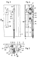
- Fig. 1 shows a schematic side view of the upper section of a bucket elevator designated as a whole with buckets 2, which are each attached at the same pitch to an endless belt 3 which rotates around two drums 4, of which only one in Fig. 1 Drum is recognizable.
- a drum 4 is designed as a drive drum, which can be driven by a drive, not shown, and the other drum as a tensioning drum, by means of which the belt 3 can be tensioned.
- the belt 3 is made endless with a clamping device designated 5 as a whole, which can best be seen from FIG. 2.
- a clamping device designated 5 As a whole, which can best be seen from FIG. 2.
- the two end sections 3 ' of the belt 3 led outward at right angles from the plane of the belt and arranged between two shaped pieces 6, 6 made of metal and a central shaped wedge 7 and screwed with twelve screw connections 8, each consisting of a screw 9, a nut 10, a lock nut 11 and washers .
- the screws 9 are expansion screws which are tightened during assembly with a considerable amount of pretension in order to prevent the belt end sections 3 'from being released from the clamping device during operation.
- the clamping device 5 is provided with a device for monitoring the pretension of the screw connections 8, which provides a warning or switch-off signal generated when the preload of the screw connections 8 falls below a predefined preload limit value. Since it has been shown that the pretension of all screw connections 8 drops substantially uniformly, it is sufficient if only one screw connection 8 '(see FIG. 4) is monitored, as is described in detail below. Be there pointed out that only three screw connections are shown in Fig. 4, while the rest are only indicated by crosses.
- a locking washer 12 with a lug 12' is provided between the nut 10 (or its washer) and the fitting 6 there with a through hole for the screw 9, which protrudes outwards via the fitting 6 protrudes and forms an abutment for a bolt-shaped switching part 13 during normal operation, which is acted upon in its longitudinal direction by a spring 14 which is adjustable with regard to its tensioning force, so that the end 13 'of the switching part 13 facing the nose 12' of the locking disk 12 exerts a corresponding torque on the locking disk 12.
- the spring force exerted on the switching part 13 of the spring 14 is set such that the locking disk 12 remains in the locking position shown in FIG.
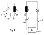
- the stationary second oscillating circuit 22 is fed by an alternating current source formed by a sine generator G with a frequency of 10 kHz, the coil 19.2 provided with an iron core being connected in series with an inductance L 2 and the capacitor 20.2 with a capacitance C 2 while the coil 19.1, which is also provided with an iron core, is connected in parallel with an inductance L 1 and the capacitor 20.1 with a capacitance C 1 of the first resonant circuit 21, the switch 23 shown in FIG. 8 in this resonant circuit 21 being closed in the normal operating state is.
- the second resonant circuit 22 contains a measuring, evaluation and control device, designated as a whole, which, among other things, has an ammeter with which the alternating current flow in the active second resonant circuit 22 is to be measured and passed on as a reference variable to the evaluation device.
- the natural frequencies of the two resonant circuits 21, 22 are tuned to the excitation frequency in the normal operating state (when the switching part 13 is in its locked rest position). The consequence of this is that the current intensity measured in the device 24 decreases due to the coupling of the two resonant circuits 21, 22 that occurs when the first resonant circuit 21 arranged on the belt 3 is moved past the second resonant circuit 22. If a corresponding change in the current intensity is therefore found in the evaluation device contained in the device 24 as the clamping device 5 provided with the first resonant circuit 21 passes by, this is a sign of a correct operating state so that the operation can be continued.
- the switching part 13 If, however, the switching part 13 is unlocked in the manner described when the pretensioning limit value falls below the monitored screw connection 8 'and moves from its rest position into its switching position, it changes the switching state of the first resonant circuit 21 and thus its reaction to the current intensity in the second resonant circuit 22 when it passes the two resonant circuits 21, 22 by opening the first resonant circuit 21 so that the alternating current flow in the active second resonant circuit 22 as it passes the clamping device 5 is practically no longer changed, that is to say the evaluation device no longer detects a significant change in the alternating current flow in the second resonant circuit 22 and then generates a warning or shutdown signal.
- the inductors L 1 and L 2 of the resonant circuits 21, 22 are designed as rod-shaped coils and (see FIG. 1) are arranged parallel to one another, specifically so that they overlap when passing without any lateral offset.
- the longitudinal extent of the two coils 19.1 and 19.2 is perpendicular to the running direction of the belt 3.
- the capacitors 20.1 and 20.2 are each integrated into a housing 19 'of the coil 19 in question and cannot be seen in the drawing.
- the one line section 25 of the first resonant circuit 21 containing the switch 23 is guided from the capacitor 20.1 or from the coil 19.1 two-wire to a socket-shaped extension 16 'of the guide 16 for the switching part 13, the two wires 25' and 25 '' being inside of the approach 16 'each formed as an electrically conductive spring tongue are between which an electrically conductive connecting element 26 is arranged (namely held in a clamped manner), which together with a pin 28 projecting radially outward from the bolt-shaped switching part 13 and engaging in a slot 27 of the socket-shaped guide 16 forms the "switch" 23 of the first resonant circuit Forms 21 and is pressed by the pin 28 from its contact position shown in FIG.
- the evaluation device integrated in the device 24 is programmed in such a way that it only triggers a warning or switch-off signal if, after a multiple (eg three times) passage of the first resonant circuit 21 past the second resonant circuit 22 in the second resonant circuit 22, no change in the current intensity is found has been around ensure that the operation of the bucket elevator is not interrupted due to a random incorrect measurement.
- the arrangement could instead be made, for example, in such a way that the switch 23 provided in the first resonant circuit 21 is open in the normal operating state, so that the second resonant circuit 22 when passing through the first resonant circuit 21 with regard to the size of its alternating current flow remains essentially unaffected, and is closed when the switching part 13 moves from its rest position into its switching position, so that with a corresponding resonance tuning of the two resonant circuits 21, 22 in the closed state of the first resonant circuit 21, the current intensity in the stationary second resonant circuit 22 as it passes of the two resonant circuits 21, 22 is changed.
- the arrangement could be such that the first resonant circuit 21 is always closed during operation, that is, it always forms a functional resonant circuit, but the tuning of the two resonant circuits 21, 22 is changed by the switching part 13 when it changes from it Moves the rest position into its switching position, preferably in such a way that, in normal operating state, there is a tuning of the two natural frequencies, each of which leads to a considerable change in the size of the alternating current flow in the second resonant circuit 22 when the first resonant circuit 21 moves past the second resonant circuit 22 , and a significant detuning of the resonance frequency of the first resonant circuit 21 takes place when that Switching part 13 moves into its switching position, so that the size of the alternating current flow in the second resonant circuit 22 does not undergo any significant change when the two resonant circuits 21, 22 pass each other.
Landscapes
- Engineering & Computer Science (AREA)
- General Engineering & Computer Science (AREA)
- Mechanical Engineering (AREA)
- Control Of Conveyors (AREA)
- Burglar Alarm Systems (AREA)
- Impression-Transfer Materials And Handling Thereof (AREA)
- Maintenance And Inspection Apparatuses For Elevators (AREA)
Applications Claiming Priority (2)
| Application Number | Priority Date | Filing Date | Title |
|---|---|---|---|
| DE19618366A DE19618366A1 (de) | 1996-05-08 | 1996-05-08 | Einrichtung zum Überwachen der Schrauben-Vorspannung einer Klemmeinrichtung eines Becherwerksgurtes |
| DE19618366 | 1996-05-08 |
Publications (3)
| Publication Number | Publication Date |
|---|---|
| EP0806379A2 true EP0806379A2 (fr) | 1997-11-12 |
| EP0806379A3 EP0806379A3 (fr) | 1998-08-05 |
| EP0806379B1 EP0806379B1 (fr) | 2001-07-04 |
Family
ID=7793628
Family Applications (1)
| Application Number | Title | Priority Date | Filing Date |
|---|---|---|---|
| EP97104114A Expired - Lifetime EP0806379B1 (fr) | 1996-05-08 | 1997-03-12 | Dispositif pour la surveillance du serrage des boulons d'un élément de jonction de la courroie d'un élévateur à godets |
Country Status (4)
| Country | Link |
|---|---|
| EP (1) | EP0806379B1 (fr) |
| DE (2) | DE19618366A1 (fr) |
| ES (1) | ES2160863T3 (fr) |
| PT (1) | PT806379E (fr) |
Cited By (1)
| Publication number | Priority date | Publication date | Assignee | Title |
|---|---|---|---|---|
| EP4039619A1 (fr) * | 2021-02-05 | 2022-08-10 | Aumund Fördertechnik GmbH | Transporteur pourvu de liaison par serrage et procédé de fonctionnement d'un transporteur |
Families Citing this family (1)
| Publication number | Priority date | Publication date | Assignee | Title |
|---|---|---|---|---|
| CN105966832A (zh) * | 2016-06-27 | 2016-09-28 | 芜湖市海联机械设备有限公司 | 一种斗式提升机的传送带结构 |
Family Cites Families (7)
| Publication number | Priority date | Publication date | Assignee | Title |
|---|---|---|---|---|
| DE1919327C3 (de) * | 1968-05-25 | 1976-01-02 | Sumitomo Electric Industries, Ltd., Osaka | Einrichtung zur Ermittlung eines Risses in einem Förderband |
| DE1810387A1 (de) * | 1968-11-22 | 1970-06-11 | Bergwerksverband Gmbh | UEberwachungseinrichtung fuer Foerderbaender |
| US3742477A (en) * | 1971-09-09 | 1973-06-26 | Goodyear Tire & Rubber | Conveyor belt condition monitoring apparatus |
| US4087800A (en) * | 1976-10-29 | 1978-05-02 | The B. F. Goodrich Company | Conveyor belt monitoring system |
| DE3346802C2 (de) * | 1983-12-23 | 1986-11-13 | Bernhard Beumer Maschinenfabrik Kg, 4720 Beckum | Einrichtung zum Überwachen des Spannungszustandes einer Schraubverbindung |
| DE4039769C1 (fr) * | 1990-12-13 | 1992-05-07 | Aumund-Foerdererbau Gmbh, Maschinenfabrik, 4134 Rheinberg, De | |
| DE4444264C2 (de) * | 1994-12-13 | 2002-05-08 | Continental Ag | Verfahren und Anordnung zur Überwachung eines Fördergurtes |
-
1996
- 1996-05-08 DE DE19618366A patent/DE19618366A1/de not_active Withdrawn
-
1997
- 1997-03-12 EP EP97104114A patent/EP0806379B1/fr not_active Expired - Lifetime
- 1997-03-12 DE DE59703938T patent/DE59703938D1/de not_active Expired - Lifetime
- 1997-03-12 PT PT97104114T patent/PT806379E/pt unknown
- 1997-03-12 ES ES97104114T patent/ES2160863T3/es not_active Expired - Lifetime
Cited By (2)
| Publication number | Priority date | Publication date | Assignee | Title |
|---|---|---|---|---|
| EP4039619A1 (fr) * | 2021-02-05 | 2022-08-10 | Aumund Fördertechnik GmbH | Transporteur pourvu de liaison par serrage et procédé de fonctionnement d'un transporteur |
| US11858744B2 (en) | 2021-02-05 | 2024-01-02 | AUMUND Fördertechnik GmbH | Conveyor with clamping connection and method for operating a conveyor |
Also Published As
| Publication number | Publication date |
|---|---|
| EP0806379B1 (fr) | 2001-07-04 |
| EP0806379A3 (fr) | 1998-08-05 |
| DE19618366A1 (de) | 1997-11-13 |
| ES2160863T3 (es) | 2001-11-16 |
| PT806379E (pt) | 2001-12-28 |
| DE59703938D1 (de) | 2001-08-09 |
Similar Documents
| Publication | Publication Date | Title |
|---|---|---|
| DE2649587C3 (de) | Detektor für elektrisch leitfähige Abrieb- bzw. Verschleißspäne | |
| DE68906238T2 (de) | Durch den zusammenbau von mehreren abnehmbaren moduleinheiten hergestellte sicherungsvorrichtung fuer schaltgeraet. | |
| DE3934952C2 (fr) | ||
| EP0514365A2 (fr) | Méthode pour la surveillance de l'état d'aiguillages ferroviaires | |
| DE1810387A1 (de) | UEberwachungseinrichtung fuer Foerderbaender | |
| DE19932481A1 (de) | Fadenliefergerät für Textilmaschinen | |
| DE19603578A1 (de) | Fördergurt und Verfahren zur Überwachung eines Fördergurtes | |
| EP0806379B1 (fr) | Dispositif pour la surveillance du serrage des boulons d'un élément de jonction de la courroie d'un élévateur à godets | |
| DE3905612C2 (fr) | ||
| DE19632347A1 (de) | Schalter, insbesondere Relais | |
| DE2644358B2 (de) | Fadenwaechter | |
| DE4225837C2 (de) | Verbindungsvorrichtung für Stromschienen in Niederspannungs-Schienensystemen zur Verteilung elektrischer Energie und Verfahren zur Einstellung der Verbindungsvorrichtung | |
| DE102004016632A1 (de) | Sicherheitsschalter zum Überwachen einer Schließposition zweier relativ zueinander beweglicher Teile | |
| WO2017077017A1 (fr) | Module de serrage à fixer à un rail porteur | |
| DE3346802C2 (de) | Einrichtung zum Überwachen des Spannungszustandes einer Schraubverbindung | |
| DE2310881A1 (de) | Vorrichtung zum anzeigen einer physikalischen groesse, die an einem sich drehenden rad gemessen ist | |
| DE1248544B (de) | UEberwachungseinrichtung fuer Foerderbaender | |
| EP0457754B1 (fr) | Commande d'aiguillage | |
| EP2165400B1 (fr) | Tambour de cable a ressort | |
| EP3212986A1 (fr) | Commutateur et système de sécurité pour surveiller une opération de travail autorisée d'une machine ou d'un dispositif | |
| DE3126358C2 (de) | Elektronische Faden-Überwachungs-Vorrichtung für Stickmaschinen | |
| EP0244432B1 (fr) | Dispositif recepteur de cable pour accouplement de cable | |
| DE3435436A1 (de) | Fadenzufuehrvorrichtung fuer textilmaschinen | |
| AT400498B (de) | Überwachungseinrichtung für wechselstrom | |
| DE3126958A1 (de) | Schutzschalter, insbesondere sprungmagnetschutzschalter |
Legal Events
| Date | Code | Title | Description |
|---|---|---|---|
| PUAI | Public reference made under article 153(3) epc to a published international application that has entered the european phase |
Free format text: ORIGINAL CODE: 0009012 |
|
| AK | Designated contracting states |
Kind code of ref document: A2 Designated state(s): BE DE ES FR IT NL PT |
|
| PUAL | Search report despatched |
Free format text: ORIGINAL CODE: 0009013 |
|
| AK | Designated contracting states |
Kind code of ref document: A3 Designated state(s): BE DE ES FR IT NL PT |
|
| 17P | Request for examination filed |
Effective date: 19980831 |
|
| GRAG | Despatch of communication of intention to grant |
Free format text: ORIGINAL CODE: EPIDOS AGRA |
|
| GRAG | Despatch of communication of intention to grant |
Free format text: ORIGINAL CODE: EPIDOS AGRA |
|
| GRAG | Despatch of communication of intention to grant |
Free format text: ORIGINAL CODE: EPIDOS AGRA |
|
| GRAH | Despatch of communication of intention to grant a patent |
Free format text: ORIGINAL CODE: EPIDOS IGRA |
|
| 17Q | First examination report despatched |
Effective date: 20001201 |
|
| GRAH | Despatch of communication of intention to grant a patent |
Free format text: ORIGINAL CODE: EPIDOS IGRA |
|
| RAP1 | Party data changed (applicant data changed or rights of an application transferred) |
Owner name: BEUMER MASCHINENFABRIK GMBH & CO. KG |
|
| GRAA | (expected) grant |
Free format text: ORIGINAL CODE: 0009210 |
|
| AK | Designated contracting states |
Kind code of ref document: B1 Designated state(s): BE DE ES FR IT NL PT |
|
| ET | Fr: translation filed | ||
| REF | Corresponds to: |
Ref document number: 59703938 Country of ref document: DE Date of ref document: 20010809 |
|
| ITF | It: translation for a ep patent filed | ||
| REG | Reference to a national code |
Ref country code: ES Ref legal event code: FG2A Ref document number: 2160863 Country of ref document: ES Kind code of ref document: T3 |
|
| REG | Reference to a national code |
Ref country code: PT Ref legal event code: SC4A Free format text: AVAILABILITY OF NATIONAL TRANSLATION Effective date: 20010920 |
|
| PLBE | No opposition filed within time limit |
Free format text: ORIGINAL CODE: 0009261 |
|
| STAA | Information on the status of an ep patent application or granted ep patent |
Free format text: STATUS: NO OPPOSITION FILED WITHIN TIME LIMIT |
|
| 26N | No opposition filed | ||
| NLS | Nl: assignments of ep-patents |
Owner name: BEUMER GMBH & CO. KG Effective date: 20080229 |
|
| REG | Reference to a national code |
Ref country code: ES Ref legal event code: PC2A |
|
| REG | Reference to a national code |
Ref country code: PT Ref legal event code: PC4A Owner name: BEUMER GMBH & CO KG, DE Effective date: 20080821 |
|
| PGFP | Annual fee paid to national office [announced via postgrant information from national office to epo] |
Ref country code: PT Payment date: 20090311 Year of fee payment: 13 Ref country code: NL Payment date: 20090303 Year of fee payment: 13 |
|
| PGFP | Annual fee paid to national office [announced via postgrant information from national office to epo] |
Ref country code: ES Payment date: 20090428 Year of fee payment: 13 |
|
| PGFP | Annual fee paid to national office [announced via postgrant information from national office to epo] |
Ref country code: IT Payment date: 20090317 Year of fee payment: 13 |
|
| PGFP | Annual fee paid to national office [announced via postgrant information from national office to epo] |
Ref country code: BE Payment date: 20090401 Year of fee payment: 13 |
|
| PGFP | Annual fee paid to national office [announced via postgrant information from national office to epo] |
Ref country code: FR Payment date: 20090316 Year of fee payment: 13 |
|
| REG | Reference to a national code |
Ref country code: PT Ref legal event code: MM4A Free format text: LAPSE DUE TO NON-PAYMENT OF FEES Effective date: 20100913 |
|
| BERE | Be: lapsed |
Owner name: *BEUMER MASCHINENFABRIK G.M.B.H. & CO. K.G. Effective date: 20100331 |
|
| REG | Reference to a national code |
Ref country code: NL Ref legal event code: V1 Effective date: 20101001 |
|
| REG | Reference to a national code |
Ref country code: FR Ref legal event code: ST Effective date: 20101130 |
|
| PG25 | Lapsed in a contracting state [announced via postgrant information from national office to epo] |
Ref country code: PT Free format text: LAPSE BECAUSE OF NON-PAYMENT OF DUE FEES Effective date: 20100913 Ref country code: NL Free format text: LAPSE BECAUSE OF NON-PAYMENT OF DUE FEES Effective date: 20101001 Ref country code: FR Free format text: LAPSE BECAUSE OF NON-PAYMENT OF DUE FEES Effective date: 20100331 |
|
| PG25 | Lapsed in a contracting state [announced via postgrant information from national office to epo] |
Ref country code: BE Free format text: LAPSE BECAUSE OF NON-PAYMENT OF DUE FEES Effective date: 20100331 |
|
| PG25 | Lapsed in a contracting state [announced via postgrant information from national office to epo] |
Ref country code: IT Free format text: LAPSE BECAUSE OF NON-PAYMENT OF DUE FEES Effective date: 20100312 |
|
| REG | Reference to a national code |
Ref country code: ES Ref legal event code: FD2A Effective date: 20110419 |
|
| PG25 | Lapsed in a contracting state [announced via postgrant information from national office to epo] |
Ref country code: ES Free format text: LAPSE BECAUSE OF NON-PAYMENT OF DUE FEES Effective date: 20110404 |
|
| PG25 | Lapsed in a contracting state [announced via postgrant information from national office to epo] |
Ref country code: ES Free format text: LAPSE BECAUSE OF NON-PAYMENT OF DUE FEES Effective date: 20100313 |
|
| PGFP | Annual fee paid to national office [announced via postgrant information from national office to epo] |
Ref country code: DE Payment date: 20130424 Year of fee payment: 17 |
|
| REG | Reference to a national code |
Ref country code: DE Ref legal event code: R119 Ref document number: 59703938 Country of ref document: DE |
|
| REG | Reference to a national code |
Ref country code: DE Ref legal event code: R119 Ref document number: 59703938 Country of ref document: DE Effective date: 20141001 |
|
| PG25 | Lapsed in a contracting state [announced via postgrant information from national office to epo] |
Ref country code: DE Free format text: LAPSE BECAUSE OF NON-PAYMENT OF DUE FEES Effective date: 20141001 |