EP0806379A2 - Device for monitoring the thighteness of the bolts from a belt-clamping device of a bucket elevator - Google Patents
Device for monitoring the thighteness of the bolts from a belt-clamping device of a bucket elevator Download PDFInfo
- Publication number
- EP0806379A2 EP0806379A2 EP97104114A EP97104114A EP0806379A2 EP 0806379 A2 EP0806379 A2 EP 0806379A2 EP 97104114 A EP97104114 A EP 97104114A EP 97104114 A EP97104114 A EP 97104114A EP 0806379 A2 EP0806379 A2 EP 0806379A2
- Authority
- EP
- European Patent Office
- Prior art keywords
- resonant circuit
- switching part
- switching
- rest position
- belt
- Prior art date
- Legal status (The legal status is an assumption and is not a legal conclusion. Google has not performed a legal analysis and makes no representation as to the accuracy of the status listed.)
- Granted
Links
Images


Classifications
-
- F—MECHANICAL ENGINEERING; LIGHTING; HEATING; WEAPONS; BLASTING
- F16—ENGINEERING ELEMENTS AND UNITS; GENERAL MEASURES FOR PRODUCING AND MAINTAINING EFFECTIVE FUNCTIONING OF MACHINES OR INSTALLATIONS; THERMAL INSULATION IN GENERAL
- F16G—BELTS, CABLES, OR ROPES, PREDOMINANTLY USED FOR DRIVING PURPOSES; CHAINS; FITTINGS PREDOMINANTLY USED THEREFOR
- F16G3/00—Belt fastenings, e.g. for conveyor belts
- F16G3/06—Belt fastenings, e.g. for conveyor belts with outwardly-bent, mutually-connected belt ends
Definitions
- the invention relates to a device for monitoring the screw pretension of a screwed clamping device for connecting the belt ends of a bucket elevator belt, the belt ends of which are clamped between clamping pieces which are connected to one another by pretensioned screws, with a switching part arranged on the screw connection to be monitored, which is in normal operation Operating state, that is, with a sufficiently large pretension of the screw connection, in a rest position, and which is automatically in a warning or when a predetermined pretension limit value is undershot Switch position triggering switch-off signal moved.
- the second nut serves as a lock nut, which is to prevent loosening of the screw connection.
- the switching part consists of a bolt arranged and guided transversely to the longitudinal direction of the belt on the clamping device, which is acted upon by a compression spring and in the normal operating state against the force generated by the spring is held in its rest position by an abutment in which its actuating end is located adjacent to the corresponding belt edge in the belt area.
- the abutment consists of a disc arranged between a fitting and the screw connection to be monitored, which is in positive engagement with the switching part on a nose projecting in the direction of the switching part and holds it against the force of the spring acting on the switching part in its rest position, as long as the due to the pretension of the screw connection, frictional forces acting on the disk generate a torque which is greater than the torque exerted by the switching part.
- the triggering of the known monitoring device can be effected quite precisely and simply at a predetermined preload limit value for the screw connection to be monitored, by using this preload limit value the torque is empirically determined with which the disc must be acted upon in order to be able to be rotated from its locked position for the switching part into its release position, and by then measuring the spring force acting on the switching part which generates the torque exerted on the disc via the switching part .
- the switching part protrudes laterally in its switching position to the extent that it collides with the switch housing and damages or tears off the switch, or that it contacts the bucket elevator housing or existing caking runs there and is bent or torn off so that it can no longer operate the switch.
- the present invention is therefore based on the object of improving the known monitoring device in such a way that that a warning or shutdown signal can be triggered without contact by means of the switching part if the pre-tensioning limit value is undershot, without the need to actuate a stationary switch.
- a passive first electrical resonant circuit is arranged in the region of the switching part on the belt and a second electrical resonant circuit excited by an alternating current source with a constant frequency is arranged in a stationary manner adjacent to the movement path of the clamping device, the current intensity in the second resonant circuit as it passes the two resonant circuits have a desired value when the switching part is in its rest position; that the switching part automatically changes the original switching state of the first resonant circuit when it moves from its rest position into its switching position such that the reaction of the first resonant circuit to the current in the second resonant circuit when it passes through the two resonant circuits is changed compared to the reaction in the original switching state; and that a current meter connected to an evaluation and control device is arranged in the second oscillating circuit, the evaluation device comparing the actual current measured in each case when it passes the two oscillating circuits with the desired current in the normal operating state and the control device generating a warning or
- an oscillating circuit is understood to mean an electrical circuit which has two energy stores and is capable of carrying out free oscillations of the current and the voltage, the one energy store for the electrical field energy being a capacitor and the other energy store for the magnetic field energy being a coil.
- each resonant circuit contains any losses that can be represented in an ohmic resistor, but are not taken into account below, since they are essentially irrelevant for the subject matter of the invention.
- An electrical resonant circuit always executes free vibrations when it e.g. triggered by a shift shock and then left to its own devices. If, on the other hand, it is fed with alternating current, it executes forced vibrations (after a short transition period). If the excitation frequency is essentially equal to the natural frequency, one speaks of a resonance circuit or of resonance operation.
- the alternating current flow in a resonant circuit excited by an alternating current source changes when a second electrical resonant circuit is brought into the region of its magnetic field.
- the reaction of the passive resonant circuit on the current strength of the excited resonant circuit is increased however, if (at least) the excited resonant circuit is operated in resonance, and is particularly large if both resonant circuits have a natural frequency which essentially corresponds to the excitation frequency of the excited resonant circuit.
- the excited second resonant circuit is operated in resonance, and most preferably also provided that the natural frequency of the passive first resonant circuit (at least ) in one of the two positions of the switching part is essentially matched to the excitation frequency or the natural frequency of the excited second resonant circuit, that is to say is also operated in resonance.
- the strength of the alternating current flowing in the first resonant circuit is significantly reduced when the first resonant circuit passes the second resonant circuit.
- the current strength that occurs represents the target current strength for the normal operating state in which the pretension of the monitored screw connection is still above the pretension limit value.
- the switching part moves out of its rest position into its Moving the switching position and thereby changing the switching state of the first resonant circuit and thus the reaction of the first resonant circuit to the second resonant circuit with respect to its current strength, for example by opening the initially closed first resonant circuit or detuning the (remaining closed) first resonant circuit, the alternating current flow becomes Not or hardly changed in the first resonant circuit when the second resonant circuit passes the first resonant circuit, so that the evaluation device determines that the actual value of the current intensity deviates significantly from its target value when passing the two resonant circuits, and a corresponding signal to the Control device there.
- the second resonant circuit fed by the alternating current source is preferably designed as a series resonant circuit, the coil and capacitor of which are connected in series, and the (passive) first resonant circuit as a parallel resonant circuit.
- the switching part can be part of the first resonant circuit or can be connected to a part of the first resonant circuit in order to detune or tune the two resonant circuits when the switching part is moved from its rest position into its switching position.
- the switching part can be the coil core of the first resonant circuit or can be connected to it in such a way that the coil core is moved relative to the coil by changing the inductance of the first resonant circuit when the switching part moves from its rest position into its switching position.
- the switching part is designed or arranged in such a way that when it moves from its rest position into its switching position it opens the previously closed first resonant circuit or closes the previously opened first resonant circuit and thus compared to the previous state of the first resonant circuit. and at the same time in relation to the second resonant circuit - "out of tune".
- a switch of the first resonant circuit can be arranged in the movement path of the switching part, which switch is actuated by the switching part when it moves from its rest position into its switching position, the switch either being opened or closed.
- a line section of the first resonant circuit can also be arranged in the movement path of the switching part, which line section is severed by the switching part when it moves from its rest position into its switching position.
- the inductances of the resonant circuits are preferred as rod-shaped coils formed, the coils of the two resonant circuits preferably substantially parallel to one another and further arranged so that they overlap when passing through the two resonant circuits, it has also proven to be particularly useful if the coils are perpendicular to the longitudinal direction of the Belt are arranged.
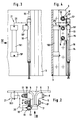
- Fig. 1 shows a schematic side view of the upper section of a bucket elevator designated as a whole with buckets 2, which are each attached at the same pitch to an endless belt 3 which rotates around two drums 4, of which only one in Fig. 1 Drum is recognizable.
- a drum 4 is designed as a drive drum, which can be driven by a drive, not shown, and the other drum as a tensioning drum, by means of which the belt 3 can be tensioned.
- the belt 3 is made endless with a clamping device designated 5 as a whole, which can best be seen from FIG. 2.
- a clamping device designated 5 As a whole, which can best be seen from FIG. 2.
- the two end sections 3 ' of the belt 3 led outward at right angles from the plane of the belt and arranged between two shaped pieces 6, 6 made of metal and a central shaped wedge 7 and screwed with twelve screw connections 8, each consisting of a screw 9, a nut 10, a lock nut 11 and washers .
- the screws 9 are expansion screws which are tightened during assembly with a considerable amount of pretension in order to prevent the belt end sections 3 'from being released from the clamping device during operation.
- the clamping device 5 is provided with a device for monitoring the pretension of the screw connections 8, which provides a warning or switch-off signal generated when the preload of the screw connections 8 falls below a predefined preload limit value. Since it has been shown that the pretension of all screw connections 8 drops substantially uniformly, it is sufficient if only one screw connection 8 '(see FIG. 4) is monitored, as is described in detail below. Be there pointed out that only three screw connections are shown in Fig. 4, while the rest are only indicated by crosses.
- a locking washer 12 with a lug 12' is provided between the nut 10 (or its washer) and the fitting 6 there with a through hole for the screw 9, which protrudes outwards via the fitting 6 protrudes and forms an abutment for a bolt-shaped switching part 13 during normal operation, which is acted upon in its longitudinal direction by a spring 14 which is adjustable with regard to its tensioning force, so that the end 13 'of the switching part 13 facing the nose 12' of the locking disk 12 exerts a corresponding torque on the locking disk 12.
- the spring force exerted on the switching part 13 of the spring 14 is set such that the locking disk 12 remains in the locking position shown in FIG.
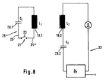
- the stationary second oscillating circuit 22 is fed by an alternating current source formed by a sine generator G with a frequency of 10 kHz, the coil 19.2 provided with an iron core being connected in series with an inductance L 2 and the capacitor 20.2 with a capacitance C 2 while the coil 19.1, which is also provided with an iron core, is connected in parallel with an inductance L 1 and the capacitor 20.1 with a capacitance C 1 of the first resonant circuit 21, the switch 23 shown in FIG. 8 in this resonant circuit 21 being closed in the normal operating state is.
- the second resonant circuit 22 contains a measuring, evaluation and control device, designated as a whole, which, among other things, has an ammeter with which the alternating current flow in the active second resonant circuit 22 is to be measured and passed on as a reference variable to the evaluation device.
- the natural frequencies of the two resonant circuits 21, 22 are tuned to the excitation frequency in the normal operating state (when the switching part 13 is in its locked rest position). The consequence of this is that the current intensity measured in the device 24 decreases due to the coupling of the two resonant circuits 21, 22 that occurs when the first resonant circuit 21 arranged on the belt 3 is moved past the second resonant circuit 22. If a corresponding change in the current intensity is therefore found in the evaluation device contained in the device 24 as the clamping device 5 provided with the first resonant circuit 21 passes by, this is a sign of a correct operating state so that the operation can be continued.
- the switching part 13 If, however, the switching part 13 is unlocked in the manner described when the pretensioning limit value falls below the monitored screw connection 8 'and moves from its rest position into its switching position, it changes the switching state of the first resonant circuit 21 and thus its reaction to the current intensity in the second resonant circuit 22 when it passes the two resonant circuits 21, 22 by opening the first resonant circuit 21 so that the alternating current flow in the active second resonant circuit 22 as it passes the clamping device 5 is practically no longer changed, that is to say the evaluation device no longer detects a significant change in the alternating current flow in the second resonant circuit 22 and then generates a warning or shutdown signal.
- the inductors L 1 and L 2 of the resonant circuits 21, 22 are designed as rod-shaped coils and (see FIG. 1) are arranged parallel to one another, specifically so that they overlap when passing without any lateral offset.
- the longitudinal extent of the two coils 19.1 and 19.2 is perpendicular to the running direction of the belt 3.
- the capacitors 20.1 and 20.2 are each integrated into a housing 19 'of the coil 19 in question and cannot be seen in the drawing.
- the one line section 25 of the first resonant circuit 21 containing the switch 23 is guided from the capacitor 20.1 or from the coil 19.1 two-wire to a socket-shaped extension 16 'of the guide 16 for the switching part 13, the two wires 25' and 25 '' being inside of the approach 16 'each formed as an electrically conductive spring tongue are between which an electrically conductive connecting element 26 is arranged (namely held in a clamped manner), which together with a pin 28 projecting radially outward from the bolt-shaped switching part 13 and engaging in a slot 27 of the socket-shaped guide 16 forms the "switch" 23 of the first resonant circuit Forms 21 and is pressed by the pin 28 from its contact position shown in FIG.
- the evaluation device integrated in the device 24 is programmed in such a way that it only triggers a warning or switch-off signal if, after a multiple (eg three times) passage of the first resonant circuit 21 past the second resonant circuit 22 in the second resonant circuit 22, no change in the current intensity is found has been around ensure that the operation of the bucket elevator is not interrupted due to a random incorrect measurement.
- the arrangement could instead be made, for example, in such a way that the switch 23 provided in the first resonant circuit 21 is open in the normal operating state, so that the second resonant circuit 22 when passing through the first resonant circuit 21 with regard to the size of its alternating current flow remains essentially unaffected, and is closed when the switching part 13 moves from its rest position into its switching position, so that with a corresponding resonance tuning of the two resonant circuits 21, 22 in the closed state of the first resonant circuit 21, the current intensity in the stationary second resonant circuit 22 as it passes of the two resonant circuits 21, 22 is changed.
- the arrangement could be such that the first resonant circuit 21 is always closed during operation, that is, it always forms a functional resonant circuit, but the tuning of the two resonant circuits 21, 22 is changed by the switching part 13 when it changes from it Moves the rest position into its switching position, preferably in such a way that, in normal operating state, there is a tuning of the two natural frequencies, each of which leads to a considerable change in the size of the alternating current flow in the second resonant circuit 22 when the first resonant circuit 21 moves past the second resonant circuit 22 , and a significant detuning of the resonance frequency of the first resonant circuit 21 takes place when that Switching part 13 moves into its switching position, so that the size of the alternating current flow in the second resonant circuit 22 does not undergo any significant change when the two resonant circuits 21, 22 pass each other.
Abstract
Description
Die Erfindung betrifft eine Einrichtung zum Überwachen der Schrauben-Vorspannung einer verschraubten Klemmeinrichtung zum Verbinden der Gurtenden eines Becherwerkgurtes, dessen Gurtenden zwischen Klemmstücken eingespannt sind, die mit vorgespannten Schrauben miteinander verbunden sind, mit einem an der zu überwachenden Schraubverbindung angeordneten Schaltteil, welches sich im normalen Betriebszustand, also bei ausreichend großer Vorspannung der Schraubverbindung, in einer Ruhestellung befindet, und welches sich bei einem Unterschreiten eines vorgegebenen Vorspannungs-Grenzwertes selbsttätig in eine ein Warn- oder Abschaltsignal auslösende Schaltstellung bewegt.The invention relates to a device for monitoring the screw pretension of a screwed clamping device for connecting the belt ends of a bucket elevator belt, the belt ends of which are clamped between clamping pieces which are connected to one another by pretensioned screws, with a switching part arranged on the screw connection to be monitored, which is in normal operation Operating state, that is, with a sufficiently large pretension of the screw connection, in a rest position, and which is automatically in a warning or when a predetermined pretension limit value is undershot Switch position triggering switch-off signal moved.
Um einen Becherwerksgurt endlos zu machen, werden seine Endabschnitte an der Verbindungsstelle nach außen abgewinkelt, zwischen dem dortigen Gurtverlauf entsprechend angepaßte Klemmstücke geführt und diese mit mehreren jeweils aus einer Schraube und i.a. zwei Muttern bestehenden Schraubverbindungen verschraubt, wobei die zweite Mutter als Kontermutter dient, die ein Lösen der Schraubverbindung verhindern soll.In order to make a bucket elevator belt endless, its end sections are angled outwards at the connection point, appropriately adapted clamping pieces are guided between the belt course there, and these are each fitted with a screw and i.a. screwed two existing screw connections, the second nut serves as a lock nut, which is to prevent loosening of the screw connection.
Die Schraubverbindungen einer derartigen Klemmeinrichtung sind mit einer erheblichen Vorspannung anzuziehen, um ausreichend große Klemm- bzw. Andrückkräfte zwischen den Klemmstücken und den zwischen ihnen angeordneten Gurtenden zu erzeugen, die ein Ausreißen der Gurtenden aus der Klemmeinrichtung verhindern, da dieses einen Absturz des mit den (im allgemeinen z.T. mit Schüttgut gefüllten) Bechern versehenen Gurtes mit einem entsprechenden Betriebsausfall sowie einer erheblichen Beschädigung des Becherwerkes zur Folge hätte. Während des Betriebes sinkt die aufgebrachte Vorspannung durch Setzerscheinungen in den Gewinden der Schrauben und Muttern sowie insbesondere in den eingeklemmten Gurtabschnitten erheblich ab. Dieses ist auch dann noch der Fall, wenn die Schraubverbindungen nach gewisser Betriebszeit (ggfs. sogar mehrfach) nachgespannt werden, weil die Setzerscheinungen in den eingespannten Gurtabschnitten sich über einen längeren Zeitraum fortsetzen können, so daß sich die aufgebrachte Vorspannung (ggfs. bis auf Null) entsprechend verringert.The screw connections of such a clamping device are to be tightened with considerable pretension in order to generate sufficiently large clamping or pressing forces between the clamping pieces and the belt ends arranged between them, which prevent the belt ends from being torn out of the clamping device, since this prevents the belt, which in some cases is filled with bulk material), would result in a corresponding breakdown and considerable damage to the bucket elevator. During operation, the applied pre-tension drops considerably due to settling in the threads of the screws and nuts and in particular in the clamped belt sections. This is also the case if the screw connections are retightened after a certain operating time (possibly even several times) because the settling phenomena in the clamped belt sections can continue over a longer period of time, so that the pre-tension applied (possibly down to zero ) reduced accordingly.
Es ist daher aus Sicherheitsgründen geboten, den Spannungszustand der Schraubverbindungen von derartigen Klemmeinrichtungen während des Betriebes ständig zu überwachen, und sicherzustellen, daß ein Warnsignal oder ein Abschaltsignal für den Becherwerksantrieb erzeugt wird, wenn die Schraubenvorspannung einen vorgegebenen unteren Grenzwert erreicht hat, damit das Bedienungspersonal darauf aufmerksam gemacht wird, daß die Schraubverbindungen der Klemmeinrichtung nachgespannt werden müssen.For safety reasons, it is therefore necessary to constantly monitor the voltage state of the screw connections of such clamping devices during operation and to ensure that a warning signal or a switch-off signal for the bucket elevator drive is generated when the screw preload has reached a predetermined lower limit value so that the operating personnel can be sure of it Attention is drawn to the fact that the screw connections of the clamping device have to be retightened.
Dabei reicht es im allgemeinen aus, wenn nur eine Schraubverbindung der Klemmeinrichtung entsprechend überwacht wird, da sich gezeigt hat, daß sich die Vorspannung der einzelnen Schraubverbindungen einer Klemmeinrichtung während des Betriebes im allgemeinen mehr oder weniger gleichmäßig verändert, so daß eine einzelne Schraubverbindung für sämtliche Schraubverbindungen repräsentativ ist, zumal der vorgegebene Vorspannungs-Grenzwert so hoch gewählt wird, daß er noch deutlich über dem kritischen Wert liegt, bei dem es zu einem Lösen der Gurtendabschnitte aus der Klemmeinrichtung kommt, so daß es unkritisch ist, wenn der Vorspannungs-Grenzwert ggfs. an anderen Schraubverbindungen bereits erreicht ist und etwas unterschritten wird, bevor dieses an der überwachten Schraubverbindung der Fall ist.It is generally sufficient if only one screw connection of the clamping device is monitored accordingly, since it has been shown that the pretensioning of the individual screw connections of a clamping device generally changes more or less uniformly during operation, so that a single screw connection for all screw connections is representative, especially since the predetermined pretension limit value is chosen so high that it is still significantly above the critical value at which the belt end sections are released from the clamping device, so that it is not critical if the pretension limit value is possibly. on other screw connections has already been reached and is slightly below before this is the case on the monitored screw connection.
Bei einer aus der DE 33 46 802 C2 bekannten gattungsgemäßen Überwachungseinrichtung besteht das Schaltteil aus einem quer zur Gurtlängsrichtung an der Klemmeinrichtung angeordneten und geführten Bolzen, der von einer Druckfeder beaufschlagt ist und im normalen Betriebszustand gegen die von der Feder erzeugte Kraft von einem Widerlager in seiner Ruhestellung gehalten wird, in welcher sich sein Betätigungsende benachbart zu dem entsprechenden Gurtrand im Gurtbereich befindet. Das Widerlager besteht aus einer zwischen einem Formstück und der zu überwachenden Schraubverbindung angeordneten Scheibe, die an einer in Richtung auf das Schaltteil vorstehenden Nase mit dem Schaltteil in formschlüssigem Eingriff ist und dieses gegen die Kraft der das Schaltteil beaufschlagenden Feder in seiner Ruhestellung hält, solange die aufgrund der Vorspannung der Schraubverbindung erzeugten, an der Scheibe wirksamen Reibungskräfte ein Drehmoment erzeugen, welches größer als das von dem Schaltteil ausgeübte Drehmoment ist. Sinken die an der Scheibe wirksamen Reibungskräfte aufgrund einer Verminderung der Schraubenvorspannung ab, so wird ein Zustand erreicht, bei dem das aufgrund der Federbeaufschlagung von dem Schaltteil auf die Scheibe ausgeübte Drehmoment größer ist als das von den an der Scheibe wirksamen Reibungskräften erzeugte Gegenmoment, so daß das Schaltteil die Scheibe um die Längsachse der entsprechenden Schraube aus seinem Bewegungspfad herausdreht und in seine Schaltstellung gelangt, in welcher sein Betätigungsende seitlich über den Gurt soweit vorsteht, daß es beim Umlauf des Gurtes mit einem stationär am Becherwerksgehäuse angeordneten Schalter in Eingriff kommt, der dabei ein Warn- oder Abschaltsignal auslöst.In a generic monitoring device known from DE 33 46 802 C2, the switching part consists of a bolt arranged and guided transversely to the longitudinal direction of the belt on the clamping device, which is acted upon by a compression spring and in the normal operating state against the force generated by the spring is held in its rest position by an abutment in which its actuating end is located adjacent to the corresponding belt edge in the belt area. The abutment consists of a disc arranged between a fitting and the screw connection to be monitored, which is in positive engagement with the switching part on a nose projecting in the direction of the switching part and holds it against the force of the spring acting on the switching part in its rest position, as long as the due to the pretension of the screw connection, frictional forces acting on the disk generate a torque which is greater than the torque exerted by the switching part. If the frictional forces acting on the disc decrease due to a reduction in the screw preload, a state is reached in which the torque exerted by the switching part on the disc due to the spring action is greater than the counter-torque generated by the frictional forces acting on the disc, so that the switching part rotates the disk about the longitudinal axis of the corresponding screw out of its path of movement and reaches its switching position, in which its actuating end projects laterally beyond the belt to such an extent that when the belt rotates, it comes into engagement with a switch arranged in a stationary manner on the bucket elevator housing, which thereby triggers a warning or shutdown signal.
Dabei läßt sich die Auslösung der bekannten Überwachungseinrichtung bei einem vorgegebenen Vorspannungs-Grenzwert für die zu überwachende Schraubverbindung recht genau und einfach bewirken, indem man bei diesem Vorspannungs-Grenzwert das Drehmoment empirisch ermittelt, mit dem die Scheibe beaufschlagt werden muß, um aus ihrer Sperrstellung für das Schaltteil in ihre Freigabestellung verdreht werden zu können, und indem man danach die das Schaltteil beaufschlagende Federkraft bemißt, die das über das Schaltteil auf die Scheibe ausgeübte Drehmoment erzeugt.In this case, the triggering of the known monitoring device can be effected quite precisely and simply at a predetermined preload limit value for the screw connection to be monitored, by using this preload limit value the torque is empirically determined with which the disc must be acted upon in order to be able to be rotated from its locked position for the switching part into its release position, and by then measuring the spring force acting on the switching part which generates the torque exerted on the disc via the switching part .
Obwohl sich diese bekannte Überwachungseinrichtung prinzipiell bestens bewährt hat, kann es aufgrund der mechanischen Schaltung zwischen dem mit dem Gurt umlaufenden Schaltteil und dem dem Schaltteil zugeordneten, stationär angeordneten Schalter insb. bei einem Gurtschieflauf zu Schwierigkeiten kommen, also dann, wenn sich der Gurt während des Betriebes aus seiner vorgesehenen mittigen Stellung zu den Gurttrommeln zur einen oder anderen Seite hin bewegt. Verschiebt sich nämlich der Gurt von der mit dem stationären Schalter versehenen Seite weg, so kann es dazu kommen, daß der Schalter von dem Schaltteil nicht betätigt wird, obwohl sich dieses aus seiner Ruhestellung in seine Schaltstellung bewegt hat. Verschiebt sich dagegen der Gurt auf den Trommeln in Richtung auf den Schalter, so kann es dazu kommen, daß das Schaltteil in seiner Schaltstellung seitlich soweit vorsteht, daß es mit dem Schaltergehäuse kollidiert und den Schalter beschädigt bzw. abreißt, oder daß es an das Becherwerksgehäuse bzw. dort vorhandene Anbackungen läuft und dabei verbogen oder abgerissen wird, so daß es den Schalter nicht mehr betätigen kann.Although this known monitoring device has proven itself in principle very well, difficulties can arise due to the mechanical circuit between the switching part rotating with the belt and the stationary switch assigned to the switching part, in particular in the event of belt misalignment, i.e. if the belt turns during the Operation moved from its intended central position to the belt drums to one side or the other. If the belt shifts away from the side provided with the stationary switch, it may happen that the switch is not actuated by the switching part, although it has moved from its rest position into its switching position. On the other hand, if the belt on the drums moves towards the switch, it can happen that the switching part protrudes laterally in its switching position to the extent that it collides with the switch housing and damages or tears off the switch, or that it contacts the bucket elevator housing or existing caking runs there and is bent or torn off so that it can no longer operate the switch.
Der vorliegenden Erfindung liegt daher die Aufgabe zugrunde, die bekannte Überwachungseinrichtung so zu verbessern, daß bei einem Unterschreiten des vorgegebenen Vorspannungs-Grenzwertes ein Warn- bzw. Abschaltsignal mittels des Schaltteils berührungslos auszulösen ist, ohne daß es hierfür einer Betätigung eines stationären Schalters bedarf.The present invention is therefore based on the object of improving the known monitoring device in such a way that that a warning or shutdown signal can be triggered without contact by means of the switching part if the pre-tensioning limit value is undershot, without the need to actuate a stationary switch.
Die Lösung dieser Aufgabe besteht erfindungsgemäß darin, daß im Bereich des Schaltteils am Gurt ein passiver erster elektrischer Schwingkreis und benachbart zu dem Bewegungspfad der Klemmeinrichtung stationär ein von einer Wechselstromquelle mit konstanter Frequenz erregter zweiter elektrischer Schwingkreis angeordnet ist, wobei die Stromstärke im zweiten Schwingkreis beim Passieren der beiden Schwingkreise einen Sollwert aufweist, wenn sich das Schaltteil in seiner Ruhestellung befindet; daß das Schaltteil bei seiner Bewegung aus seiner Ruhestellung in seine Schaltstellung den ursprünglichen Schaltzustand des ersten Schwingkreises selbsttätig so verändert, daß die beim Passieren der beiden Schwingkreise vorhandene Rückwirkung des ersten Schwingkreises auf die Stromstärke im zweiten Schwingkreis gegenüber der Rückwirkung im ursprünglichen Schaltzustand verändert wird; und daß im zweiten Schwingkreis ein mit einer Auswert- und Steuereinrichtung verbundener Strommesser angeordnet ist, wobei die Auswerteinrichtung die jeweils beim Passieren der beiden Schwingkreise gemessene Ist-Stromstärke mit der Soll-Stromstärke im normalen Betriebszustand vergleicht und die Steuereinrichtung ein Warn- bzw. Abschaltsignal erzeugt, wenn die Ist-Stromstärke von der Soll-Stromstärke um eine vorgegebene Differenz abweicht.The solution to this problem is according to the invention that a passive first electrical resonant circuit is arranged in the region of the switching part on the belt and a second electrical resonant circuit excited by an alternating current source with a constant frequency is arranged in a stationary manner adjacent to the movement path of the clamping device, the current intensity in the second resonant circuit as it passes the two resonant circuits have a desired value when the switching part is in its rest position; that the switching part automatically changes the original switching state of the first resonant circuit when it moves from its rest position into its switching position such that the reaction of the first resonant circuit to the current in the second resonant circuit when it passes through the two resonant circuits is changed compared to the reaction in the original switching state; and that a current meter connected to an evaluation and control device is arranged in the second oscillating circuit, the evaluation device comparing the actual current measured in each case when it passes the two oscillating circuits with the desired current in the normal operating state and the control device generating a warning or shutdown signal , if the actual current deviates from the target current by a predetermined difference.
Unter einem Schwingkreis versteht man bekanntlich einen zwei Energiespeicher aufweisenden elektrischen Stromkreis, der imstande ist, freie Schwingungen des Stromes und der Spannung auszuführen, wobei der eine Energiespeicher für die elektrische Feldenergie ein Kondensator und der andere Energiespeicher für die magnetische Feldenergie eine Spule ist. Außerdem enthält jeder Schwingkreis irgendwelche Verluste, die in einem Ohmschen Widerstand dargestellt werden können, nachstehend jedoch unberücksichtigt bleiben, da sie für den Erfindungsgegenstand grundsätzlich im wesentlichen unerheblich sind.As is known, an oscillating circuit is understood to mean an electrical circuit which has two energy stores and is capable of carrying out free oscillations of the current and the voltage, the one energy store for the electrical field energy being a capacitor and the other energy store for the magnetic field energy being a coil. In addition, each resonant circuit contains any losses that can be represented in an ohmic resistor, but are not taken into account below, since they are essentially irrelevant for the subject matter of the invention.
Freie Schwingungen führt ein elektrischer Schwingkreis stets dann aus, wenn er z.B. durch einen Schaltstoß angestoßen und sich dann selbst überlassen wird. Speist man ihn dagegen mit Wechselstrom, so führt er (nach einer kurzen Übergangszeit) erzwungene Schwingungen aus. Ist dabei die Erregerfrequenz im wesentlichen gleich der Eigenfrequenz, so spricht man von einem Resonanzkreis bzw. von Resonanzbetrieb.An electrical resonant circuit always executes free vibrations when it e.g. triggered by a shift shock and then left to its own devices. If, on the other hand, it is fed with alternating current, it executes forced vibrations (after a short transition period). If the excitation frequency is essentially equal to the natural frequency, one speaks of a resonance circuit or of resonance operation.
Bei der erfindungsgemäßen Einrichtung wird von dem Phänomen Gebrauch gemacht, daß sich der Wechselstromfluß in einem von einer Wechselstromquelle erregten Schwingkreis verändert, wenn ein zweiter elektrischer Schwingkreis in den Bereich seines Magnetfeldes verbracht wird. Dabei ist diese Veränderung (ggfs. vernachlässigbar) klein, wenn die Eigenfrequenz der beiden Schwingkreise von der Erregerfrequenz des aktiven (= erregten) Schwingkreises erheblich abweicht. Die Rückwirkung des passiven Schwingkreises auf die Stromstärke des erregten Schwingkreises vergrößert sich jedoch, wenn (wenigstens) der erregte Schwingkreis in Resonanz betrieben wird, und ist besonders groß, wenn beide Schwingkreise eine Eigenfrequenz aufweisen, die im wesentlichen der Erregerfrequenz des erregten Schwingkreises entspricht. Um beim Absinken der Schraubenvorspannung unter den vorgegebenen Vorspannungsgrenzwert zu einem gut verwertbaren, eindeutigen Steuerungssignal zu kommen, ist daher bevorzugt vorgesehen, daß der erregte zweite Schwingkreis in Resonanz betrieben wird, und höchst bevorzugt weiterhin vorgesehen, daß auch die Eigenfrequenz des passiven ersten Schwingkreises (wenigstens) in einer der beiden Stellungen des Schaltteils im wesentlichen auf die Erregerfrequenz bzw. die Eigenfrequenz des erregten zweiten Schwingkreises abgestimmt ist, also ebenfalls in Resonanz betrieben wird.In the device according to the invention, use is made of the phenomenon that the alternating current flow in a resonant circuit excited by an alternating current source changes when a second electrical resonant circuit is brought into the region of its magnetic field. This change is small (negligible if necessary) if the natural frequency of the two resonant circuits deviates significantly from the excitation frequency of the active (= excited) resonant circuit. The reaction of the passive resonant circuit on the current strength of the excited resonant circuit is increased however, if (at least) the excited resonant circuit is operated in resonance, and is particularly large if both resonant circuits have a natural frequency which essentially corresponds to the excitation frequency of the excited resonant circuit. In order to arrive at a usable, clear control signal when the screw preload drops below the predetermined preload limit value, it is therefore preferably provided that the excited second resonant circuit is operated in resonance, and most preferably also provided that the natural frequency of the passive first resonant circuit (at least ) in one of the two positions of the switching part is essentially matched to the excitation frequency or the natural frequency of the excited second resonant circuit, that is to say is also operated in resonance.
Wenn die Eigenfrequenzen der beiden (geschlossenen) Schwingkreise also bspw. in der Ruhestellung des Schaltteils auf die Erregerfrequenz des zweiten Schwingkreises abgestimmt sind, so wird die Stärke des in dem ersten Schwingkreis fließenden Wechselstroms jeweils deutlich verringert, wenn der erste Schwingkreis den zweiten Schwingkreis passiert. Die dabei auftretende Stromstärke stellt die Soll-Stromstärke für den normalen Betriebszustand dar, in dem die Vorspannung der überwachten Schraubverbindung noch oberhalb des Vorspannungs-Grenzwertes liegt.If the natural frequencies of the two (closed) resonant circuits are matched to the excitation frequency of the second resonant circuit, for example in the rest position of the switching part, then the strength of the alternating current flowing in the first resonant circuit is significantly reduced when the first resonant circuit passes the second resonant circuit. The current strength that occurs represents the target current strength for the normal operating state in which the pretension of the monitored screw connection is still above the pretension limit value.
Unterschreitet aber die Vorspannung der überwachten Schraubverbindung den vorgegebenen Vorspannungs-Grenzwert, so daß sich das Schaltteil aus seiner Ruhestellung in seine Schaltstellung bewegt und dabei den Schaltzustand des ersten Schwingkreises und damit die Rückwirkung des ersten Schwingkreises auf den zweiten Schwingkreis bzgl. dessen Stromstärke verändert, indem es bspw. den zunächst geschlossenen ersten Schwingkreis öffnet oder den (geschlossen bleibenden) ersten Schwingkreis verstimmt, so wird der Wechselstromfluß im ersten Schwingkreis nicht bzw. kaum verändert, wenn der zweite Schwingkreis den ersten Schwingkreis passiert, so daß die Auswerteinrichtung feststellt, daß der Ist-Wert der Stromstärke von deren Soll-Wert beim Passieren der beiden Schwingkreise erheblich abweicht, und ein entsprechendes Signal an die Steuereinrichtung gibt.However, if the pretension of the monitored screw connection falls below the predefined pretension limit value, so that the switching part moves out of its rest position into its Moving the switching position and thereby changing the switching state of the first resonant circuit and thus the reaction of the first resonant circuit to the second resonant circuit with respect to its current strength, for example by opening the initially closed first resonant circuit or detuning the (remaining closed) first resonant circuit, the alternating current flow becomes Not or hardly changed in the first resonant circuit when the second resonant circuit passes the first resonant circuit, so that the evaluation device determines that the actual value of the current intensity deviates significantly from its target value when passing the two resonant circuits, and a corresponding signal to the Control device there.
In entsprechender Weise könnte verfahren werden, wenn die Eigenfrequenz des zweiten Schwingkreises im normalen Betriebszustand gegenüber der Resonanzfrequenz des ersten Schwingkreises verstimmt ist, und wenn sie durch die Bewegung des Schaltteils aus dessen Ruhestellung in dessen Schaltstellung so verändert wird, daß sie in der Schaltstellung des Schaltteils auf die Resonanzfrequenz des ersten Schaltkreises abgestimmt ist. Da dieses jedoch im praktischen Betrieb mit größeren Unsicherheiten verbunden ist als die zuvor erläuterte Variante, ist diese aus Gründen der Betriebssicherheit zu bevorzugen.A corresponding procedure could be followed if the natural frequency of the second resonant circuit in the normal operating state is out of tune with the resonance frequency of the first resonant circuit, and if it is changed by the movement of the switching part from its rest position into its switching position so that it is in the switching position of the switching part is tuned to the resonance frequency of the first circuit. However, since this is associated with greater uncertainties in practical operation than the previously explained variant, this is to be preferred for reasons of operational safety.
Bevorzugt ist der von der Wechselstromquelle gespeiste zweite Schwingkreis als Reihenschwingkreis ausgebildet, dessen Spule und Kondensator in Reihe geschaltet sind, und der (passive) erste Schwingkreis als Parallelschwingkreis.The second resonant circuit fed by the alternating current source is preferably designed as a series resonant circuit, the coil and capacitor of which are connected in series, and the (passive) first resonant circuit as a parallel resonant circuit.
Bei einer ersten Ausführungsform kann das Schaltteil Bestandteil des ersten Schwingkreises sein bzw. mit einem Teil des ersten Schwingkreises verbunden sein, um beim Bewegen des Schaltteils aus dessen Ruhestellung in seine Schaltstellung eine Verstimmung bzw. eine Abstimmung der beiden Schwingkreise zu bewirken. So kann das Schaltteil bspw. der Spulenkern des ersten Schwingkreises sein bzw. mit diesem so verbunden sein, daß der Spulenkern bei der Bewegung des Schaltteils aus dessen Ruhestellung in dessen Schaltstellung relativ zur Spule unter Veränderung der Induktivität des ersten Schwingkreises bewegt wird.In a first embodiment, the switching part can be part of the first resonant circuit or can be connected to a part of the first resonant circuit in order to detune or tune the two resonant circuits when the switching part is moved from its rest position into its switching position. For example, the switching part can be the coil core of the first resonant circuit or can be connected to it in such a way that the coil core is moved relative to the coil by changing the inductance of the first resonant circuit when the switching part moves from its rest position into its switching position.
Bei einer bevorzugten Ausgestaltung der vorliegenden Erfindung ist das Schaltteil so ausgebildet bzw. angeordnet, daß es bei seiner Bewegung aus seiner Ruhestellung in seine Schaltstellung den zuvor geschlossenen ersten Schwingkreis öffnet oder den zuvor geöffneten ersten Schwingkreis schließt und dadurch gegenüber dem vorherigen Zustand des ersten Schwingkreises - und damit zugleich in Relation zum zweiten Schwingkreis - "verstimmt". Hierfür kann im Bewegungspfad des Schaltteils ein Schalter des ersten Schwingkreises angeordnet sein, der von dem Schaltteil betätigt wird, wenn sich dieses aus seiner Ruhestellung in seine Schaltstellung bewegt, wobei der Schalter entweder geöffnet oder geschlossen wird. Stattdessen kann im Bewegungspfad des Schaltteils auch ein Leitungsabschnitt des ersten Schwingkreises angeordnet sein, der von dem Schaltteil durchtrennt wird, wenn sich dieses aus seiner Ruhestellung in seine Schaltstellung bewegt.In a preferred embodiment of the present invention, the switching part is designed or arranged in such a way that when it moves from its rest position into its switching position it opens the previously closed first resonant circuit or closes the previously opened first resonant circuit and thus compared to the previous state of the first resonant circuit. and at the same time in relation to the second resonant circuit - "out of tune". For this purpose, a switch of the first resonant circuit can be arranged in the movement path of the switching part, which switch is actuated by the switching part when it moves from its rest position into its switching position, the switch either being opened or closed. Instead, a line section of the first resonant circuit can also be arranged in the movement path of the switching part, which line section is severed by the switching part when it moves from its rest position into its switching position.
Die Induktivitäten der Schwingkreise sind bevorzugt als stabförmige Spulen ausgebildet, wobei die Spulen der beiden Schwingkreise bevorzugt im wesentlichen parallel zueinander und weiterhin so angeordnet sind, daß sie sich beim Passieren der beiden Schwingkreise im wesentlichen überdecken, wobei es sich weiterhin als besonders zweckmäßig herausgestellt hat, wenn die Spulen rechtwinklig zur Längsrichtung des Gurtes angeordnet sind.The inductances of the resonant circuits are preferred as rod-shaped coils formed, the coils of the two resonant circuits preferably substantially parallel to one another and further arranged so that they overlap when passing through the two resonant circuits, it has also proven to be particularly useful if the coils are perpendicular to the longitudinal direction of the Belt are arranged.
Bevorzugte Ausgestaltungen der vorliegenden Erfindung sind in den Unteransprüchen beschrieben.Preferred embodiments of the present invention are described in the subclaims.
Die Erfindung ist nachstehend an einem Ausführungsbeispiel unter Bezugnahme auf eine Zeichnung weiter erläutert. Es zeigt:
- Fig. 1: eine schematisierte Seitenansicht des oberen Teils eines Gurtbecherwerkes mit der die Gurtenden verbindenden Klemmeinrichtung;
- Fig. 2: eine vergrößerte Darstellung des in Fig. 1 mit einer strichpunktierten Linie II umrahmten Abschnittes, nämlich der Klemmeinrichtung sowie eines Teiles der Überwachungseinrichtung;
- Fig. 3: eine Ansicht der Darstellung gem. Fig. 2 in Richtung des Pfeiles III in Fig. 2 gesehen;
- Fig. 4: eine Ansicht der Darstellung gem. Fig. 3 in Richtung des Pfeiles IV in Fig. 3 gesehen;
- Fig. 5: eine das Schaltteil enthaltende Einzelheit gem. den Darstellungen in den Fig. 2 bis 4;
- Fig. 6: den in Fig. 5 mit einem Kreis VI umrahmten Abschnitt in einer vergrößerten Schnittdarstellung (in Richtung der Schnittlinie VI-VI in Fig. 7 gesehen);
- Fig. 7: eine Draufsicht auf die Darstellung gem. Fig. 6 in Richtung des Pfeiles VII in Fig. 6 gesehen; und
- Fig. 8: einen Schaltplan der beiden Schwingkreise der Überwachungseinrichtung.
- 1 shows a schematic side view of the upper part of a belt bucket elevator with the clamping device connecting the belt ends;
- FIG. 2 shows an enlarged representation of the section framed in FIG. 1 with a dash-dotted line II, namely the clamping device and part of the monitoring device;
- 3: a view of the representation acc. Fig. 2 seen in the direction of arrow III in Fig. 2;
- 4: a view of the representation acc. 3 in the direction of arrow IV in FIG. 3rd seen;
- Fig. 5: a detail containing the switching part acc. the representations in Figures 2 to 4;
- 6: the section framed with a circle VI in FIG. 5 in an enlarged sectional view (viewed in the direction of the section line VI-VI in FIG. 7);
- 7: a plan view of the representation acc. Fig. 6 seen in the direction of arrow VII in Fig. 6; and
- Fig. 8: a circuit diagram of the two resonant circuits of the monitoring device.
Fig. 1 zeigt in einer schematischen Seitenansicht den oberen Abschnitt eines im ganzen mit 1 bezeichneten Becherwerkes mit Bechern 2, die jeweils mit gleichem Teilungsabstand an einem endlosen Gurt 3 befestigt sind, der um zwei Trommeln 4 umläuft, von denen in Fig. 1 nur eine Trommel erkennbar ist. Dabei ist eine Trommel 4 als Antriebstrommel ausgebildet, die von einem nicht dargestellten Antrieb antreibbar ist, und die andere Trommel als Spanntrommel, mittels welcher der Gurt 3 zu spannen ist.Fig. 1 shows a schematic side view of the upper section of a bucket elevator designated as a whole with
Der Gurt 3 ist mit einer im ganzen mit 5 bezeichneten Klemmeinrichtung endlos gemacht, die am besten aus Fig. 2 erkennbar ist. Hierfür sind die beiden Endabschnitte 3' des Gurtes 3 rechtwinklig aus der Gurtverlaufsebene nach außen herausgeführt und zwischen zwei aus Metall bestehenden Formstücken 6,6 sowie einem mittleren Formkeil 7 angeordnet und mit zwölf Schraubverbindungen 8 verschraubt, die jeweils aus einer Schraube 9, einer Mutter 10, einer Kontermutter 11 sowie Unterlegscheiben bestehen. Bei den Schrauben 9 handelt es sich um Dehnschrauben, die bei der Montage mit einer erheblichen Vorspannung angezogen werden, um ein Lösen der Gurtendabschnitte 3' aus der Klemmeinrichtung während des Betriebes zu verhindern. Da es aufgrund von Setzerscheinungen in dem Gewinden der Schrauben 9 und Muttern 10,11 sowie insbesondere in den Gurtendabschnitten 3' alsbald zu einer erheblichen Verringerung der zunächst aufgebrachten Vorspannung kommt, wird das Anziehen der Schraubverbindungen 8 auf eine vorgegebene Vorspannung nach kurzer Betriebszeit (ggfs. mehrfach) wiederholt.The
Da es dennoch während des weiteren Betriebes zu einer erheblichen Verringerung der Vorspannung kommen kann und sichergestellt werden muß, daß die Gurtverbindung an der Klemmeinrichtung 5 aufrechterhalten bleibt, ist die Klemmeinrichtung 5 mit einer Einrichtung zum Überwachen der Vorspannung der Schraubverbindungen 8 versehen, die ein Warn- oder Abschaltsignal erzeugt, wenn die Vorspannung der Schraubverbindungen 8 einen vorgegebenen Vorspannungs-Grenzwert unterschreitet. Da sich gezeigt hat, daß die Vorspannung sämtlicher Schraubverbindungen 8 im wesentlichen gleichmäßig absinkt, reicht es aus, wenn lediglich eine Schraubverbindung 8' (s. Fig. 4) überwacht wird, wie dieses nachfolgend im einzelnen beschrieben ist. Dabei sei darauf verwiesen, daß in Fig. 4 nur drei Schraubverbindungen eingezeichnet sind, während die übrigen lediglich durch Kreuze angedeutet sind.Since there can nevertheless be a considerable reduction in the pretension during further operation and it must be ensured that the belt connection on the
An der hinsichtlich ihrer Vorspannung überwachten Schraubverbindung 8' ist zwischen der Mutter 10 (bzw. deren Unterlegscheibe) und dem dortigen Formstück 6 eine mit einer Durchgangsbohrung für die Schraube 9 versehene Sperrscheibe 12 mit einer Nase 12' angeordnet, welche nach außen über das Formstück 6 vorsteht und während des normalen Betriebes ein Widerlager für ein bolzenförmiges Schaltteil 13 bildet, welches von einer bezüglich ihrer Spannkraft einstellbaren Feder 14 in seiner Längsrichtung von einer Federkraft beaufschlagt ist, so daß das der Nase 12' der Sperrscheibe 12 zugekehrte Ende 13' des Schaltteils 13 ein entsprechendes Drehmoment auf die Sperrscheibe 12 ausübt. Dabei wird die auf das Schaltteil 13 ausgeübte Federkraft der Feder 14 so eingestellt, daß die Sperrscheibe 12 in der in Fig. 4 dargestellten Sperrstellung verbleibt, wenn die Vorspannung der Schraubverbindung 8' oberhalb eines vorgegebenen Vorspannungs-Grenzwertes ist, und daß die an der Sperrscheibe 12 wirksamen Reibungskräfte bei einem Unterschreiten des vorgegebenen Vorspannungs-Grenzwertes nicht mehr ausreichen, um ein Gegenmoment zu erzeugen, welches die Sperrscheibe 12 in ihrer Sperrstellung hält. Vielmehr werden die durch die Vorspannung der Schraubverbindung 8' an der Sperrscheibe 12 wirksamen Reibungskräfte bei einem Unterschreiten des Vorspannungs-Grenzwertes so klein, daß das von ihnen erzeugte Gegenmoment kleiner wird als das von dem Schaltteil 13 bzw. dessen Feder 14 erzeugte Drehmoment auf die Nase 12' der Sperrscheibe 12, so daß die Sperrscheibe 12 um die Längsachse der Schraubverbindung 8' aus dem Bewegungspfad des Schaltteils 13 (in Fig. 4 im Gegenuhrzeigersinne) herausgedreht wird und sich das Schaltteil 13 aus seiner in den Fig. 2 bis 4 dargestellten Ruhestellung in Richtung des Pfeiles 15 in eine Schaltstellung bewegt und in dieser ein Warn- oder Abschaltsignal auslöst.On the screw connection 8 'monitored with regard to its pretension, a locking
Bevor dieses im einzelnen beschrieben wird, sei noch darauf verwiesen, daß das bolzenförmige Schaltteil 13 in einer buchsenförmigen Führung 16 geführt ist, die mit einer Lasche 17 unter Verwendung zweier Schraubverbindungen 8 an ein Formstück 6 geschraubt ist.Before this is described in detail, it should also be pointed out that the bolt-shaped switching
Um beim Auslösen des Schaltteils 13 ein Warn- oder Abschaltsignal zu erzeugen, ohne daß dabei wie im Stand der Technik ein am stationären Becherwerksgehäuse 18 angeordneter Schalter unter entsprechender Berührung mechanisch betätigt zu werden braucht, ist im Bereich des Schaltteils 13 am Gurt 3 ein eine Spule 19.1 sowie einen Kondensator 20.1 aufweisender erster elektrischer Schwingkreis 21 angeordnet und benachbart zu dem endlosen Bewegungspfad der während des Betriebes um die Trommeln 4 umlaufenden Klemmeinrichtung 5 am stationären Becherwerksgehäuse 18 ein eine Spule 19.2 sowie einen Kondensator 20.2 enthaltender zweiter Schwingkreis 22 (s. Fig. 8). Der stationär angeordnete zweite Schwingkreis 22 wird von einer durch einen Sinusgenerator G gebildeten Wechselstromquelle mit einer Frequenz von 10 kHz gespeist, wobei die mit einem Eisenkern versehene Spule 19.2 mit einer Induktivität L2 und der Kondensator 20.2 mit einer Kapazität C2 in Reihe geschaltet sind, während die ebenfalls mit einem Eisenkern versehene Spule 19.1 mit einer Induktivität L1 und der Kondensator 20.1 mit einer Kapazität C1 des ersten Schwingkreises 21 parallel geschaltet sind, wobei der in Fig. 8 in diesen Schwingkreis 21 eingezeichnete Schalter 23 im normalen Betriebszustand geschlossen ist.In order to generate a warning or switch-off signal when the switching
Im zweiten Schwingkreis 22 ist eine im ganzen mit 24 bezeichnete Meß-, Auswert- und Steuereinrichtung enthalten, die u.a. einen Strommesser aufweist, mit dem der Wechselstromfluß in dem aktiven zweiten Schwingkreis 22 zu messen und als Bezugsgröße an die Auswerteinrichtung weiterzuleiten ist. Die Eigenfrequenzen der beiden Schwingkreise 21,22 sind im normalen Betriebszustand (wenn sich das Schaltteil 13 in seiner gesperrten Ruhestellung befindet) auf die Erregerfrequenz abgestimmt. Dieses hat zur Folge, daß die in der Einrichtung 24 gemessene Stromstärke aufgrund der entstehenden Kopplung der beiden Schwingkreise 21, 22 jeweils absinkt, wenn der am Gurt 3 angeordnete erste Schwingkreis 21 am zweiten Schwingkreis 22 vorbeibewegt wird. Wird daher in der in der Einrichtung 24 enthaltenen Auswerteinrichtung beim Vorbeilauf der mit dem ersten Schwingkreis 21 versehenen Klemmeinrichtung 5 eine entsprechende Änderung der Stromstärke festgestellt, so ist dieses ein Zeichen für einen ordnungsgemäßen Betriebszustand, so daß der Betrieb fortgesetzt werden kann.The second
Wird nun aber bei einem Unterschreiten des Vorspannungs-Grenzwertes an der überwachten Schraubverbindung 8' das Schaltteil 13 in der beschriebenen Weise entriegelt und bewegt sich aus seiner Ruhestellung in seine Schaltstellung, so verändert es dabei den Schaltzustand des ersten Schwingkreises 21 und damit dessen Rückwirkung auf die Stromstärke im zweiten Schwingkreis 22 beim Passieren der beiden Schwingkreise 21, 22, indem es den ersten Schwingkreis 21 öffnet, so daß der Wechselstromfluß in dem aktiven zweiten Schwingkreis 22 beim Vorbeilauf der Klemmeinrichtung 5 praktisch nicht mehr verändert wird, die Auswerteinrichtung also keine erhebliche Veränderung des Wechselstromflusses im zweiten Schwingkreis 22 mehr feststellt und daraufhin ein Warn- oder Abschaltsignal erzeugt.If, however, the switching
Wie in den Fig. 3 und 4 anhand der Spule 19.1 des ersten Schwingkreises 21 erkennbar ist, sind die Induktivitäten L1 und L2 der Schwingkreise 21,22 als stabförmige Spulen ausgebildet und (s. Fig. 1) parallel zueinander angeordnet, und zwar so, daß sie sich beim Passieren ohne seitlichen Versatz überdecken. Die Längserstreckung der beiden Spulen 19.1 und 19.2 ist rechtwinklig zur Laufrichtung des Gurtes 3.As can be seen in FIGS. 3 and 4 on the basis of the coil 19.1 of the first
Die Kondensatoren 20.1 bzw. 20.2 sind jeweils in ein Gehäuse 19' der betreffenden Spule 19 integriert und in der Zeichnung nicht erkennbar.The capacitors 20.1 and 20.2 are each integrated into a housing 19 'of the coil 19 in question and cannot be seen in the drawing.
Der den Schalter 23 enthaltende eine Leitungsabschnitt 25 des ersten Schwingkreises 21 ist vom Kondensator 20.1 bzw. von der Spule 19.1 zweiadrig zu einem buchsenförmigen Ansatz 16' der Führung 16 für das Schaltteil 13 geführt, wobei die beiden Adern 25' bzw. 25'' innerhalb des Ansatzes 16' jeweils als elektrisch leitende Federzunge ausgebildet sind, zwischen denen ein elektrisch leitendes Verbindungselement 26 angeordnet (nämlich klemmend gehalten) ist, welches zusammen mit einem radial von dem bolzenförmigen Schaltteil 13 nach außen vorstehenden, in einen Schlitz 27 der buchsenförmigen Führung 16 greifenden Stift 28 den "Schalter" 23 des ersten Schwingkreises 21 bildet und von dem Stift 28 aus seiner in Fig. 7 erkennbaren Kontaktposition gedrückt wird, wenn sich das Schaltteil 13 aus seiner Ruhestellung in Richtung des Pfeiles 15 in seine Schaltstellung bewegt, so daß der erste Schwingkreis 21 dabei unterbrochen wird. Dieses hat zur Folge, daß es aufgrund der durch das Öffnen des ersten Schwingkreises 21 erfolgten "Verstimmung" des ersten Schwingkreises 21 bezüglich der Resonanzfrequenz des zweiten Schwingkreises 22 nicht mehr zu einer elektrischen Kopplung der beiden Schwingkreise 21,22 kommt, wenn sich der erste Schwingkreis 21 am zweiten Schwingkreis 22 vorbei bewegt, weil der erste Schwingkreis 21 nach seiner Unterbrechung dabei den zweiten Schwingkreis 22 nicht mehr bezüglich dessen Wechselstromfluß beeinflussen kann, so daß die dem zweiten Schwingkreis 22 zugeordnete Auswerteinrichtung beim Passieren der beiden Schwingkreise 21,22 einen i.w. konstanten Wechselstromfluß im zweiten Schwingkreis 22 feststellt und daraufhin ein Warn- bzw. Abschaltsignal auslöst.The one
Dabei ist die in die Einrichtung 24 integrierte Auswerteinrichtung so programmiert, daß sie ein Warn- bzw. Abschaltsignal erst dann auslöst, wenn nach einem mehrfachen (z.B. dreimaligen) Vorbeilauf des ersten Schwingkreises 21 am zweiten Schwingkreis 22 im zweiten Schwingkreis 22 keine Veränderung der Stromstärke festgestellt worden ist, um sicherzustellen, daß der Betrieb des Becherwerkes nicht bereits aufgrund einer zufälligen Fehlmessung unterbrochen wird.The evaluation device integrated in the
Wie bereits weiter oben ausgeführt worden ist, könnte die Anordnung stattdessen beispielsweise auch so getroffen sein, daß der im ersten Schwingkreis 21 vorgesehene Schalter 23 im normalen Betriebszustand geöffnet ist, so daß der zweite Schwingkreis 22 beim Passieren des ersten Schwingkreises 21 hinsichtlich der Größe seines Wechselstromflusses im wesentlichen unbeeinflußt bleibt, und geschlossen wird, wenn sich das Schaltteil 13 aus seiner Ruhestellung in seine Schaltstellung bewegt, so daß bei einer entsprechenden Resonanzabstimmung der beiden Schwingkreise 21,22 im geschlossenen Zustand des ersten Schwingkreises 21 die Stromstärke im stationären zweiten Schwingkreis 22 beim Passieren der beiden Schwingkreise 21,22 verändert wird. Weiterhin könnte die Anordnung so getroffen sein, daß der erste Schwingkreis 21 während des Betriebes stets geschlossen ist, er also stets einen funktionsfähigen Schwingkreis bildet, wobei jedoch die Abstimmung der beiden Schwingkreise 21,22 durch das Schaltteil 13 verändert wird, wenn sich dieses aus seiner Ruhestellung in seine Schaltstellung bewegt, und zwar vorzugsweise derart, daß im normalen Betriebszustand eine Abstimmung der beiden Eigenfrequenzen vorliegt, die jeweils zu einer erheblichen Änderung der Größe des Wechselstromflusses im zweiten Schwingkreis 22 führt, wenn sich der erste Schwingkreis 21 an dem zweiten Schwingkreis 22 vorbeibewegt, und eine erhebliche Verstimmung der Resonanzfrequenz des ersten Schwingkreises 21 erfolgt, wenn sich das Schaltteil 13 in seine Schaltstellung bewegt, so daß dadurch die Größe des Wechselstromflusses im zweiten Schwingkreis 22 keine erhebliche Veränderung erfährt, wenn die beiden Schwingkreise 21,22 einander passieren.As has already been explained above, the arrangement could instead be made, for example, in such a way that the
- 11
- BecherwerkBucket elevator
- 22nd
- Bechercups
- 33rd
- Gurtbelt
- 3'3 '
- Endabschnitte (von 3)End sections (of 3)
- 44th
- Trommelndrums
- 55
- KlemmeinrichtungClamping device
- 66
- FormstückeFittings
- 77
- FormkeilShaped wedge
- 8,8'8.8 '
- SchraubverbindungenScrew connections
- 99
- Schraubescrew
- 1010th
- Muttermother
- 1111
- KontermutterLock nut
- 1212th
- SperrscheibeLock washer
- 12'12 '
- Nase (von 12)Nose (of 12)
- 1313
- SchaltteilSwitching part
- 13'13 '
- Ende (von 13)End (of 13)
- 1414
- Feder (für 13)Spring (for 13)
- 1515
- Pfeilarrow
- 1616
- Führung (für 13)Guided tour (for 13)
- 16'16 '
- Ansatz (von 16)Approach (of 16)
- 1717th
- LascheTab
- 1818th
- BecherwerksgehäuseBucket elevator housing
- 1919th
- SpulenDo the washing up
- 19'19 '
- Gehäuse (von 19)Housing (of 19)
- 2020th
- Kondensatorcapacitor
- 2121
- erster Schwingkreisfirst resonant circuit
- 2222
- zweiter Schwingkreissecond resonant circuit
- 2323
- Schaltercounter
- 2424th
- Meß-, Auswert- und SteuereinrichtungMeasuring, evaluation and control device
- 2525th
- elektrischer Leitungsabschnitt (von 21)electrical line section (from 21)
- 25'25 '
- Ader (von 25)Core (from 25)
- 25''25 ''
- Ader (von 25)Core (from 25)
- 2626
- VerbindungselementFastener
- 2727
- Schlitz (von 16)Slot (of 16)
- 2828
- Stiftpen
Claims (17)
Applications Claiming Priority (2)
| Application Number | Priority Date | Filing Date | Title |
|---|---|---|---|
| DE19618366 | 1996-05-08 | ||
| DE19618366A DE19618366A1 (en) | 1996-05-08 | 1996-05-08 | Device for monitoring the screw pretension of a clamping device of a bucket elevator belt |
Publications (3)
| Publication Number | Publication Date |
|---|---|
| EP0806379A2 true EP0806379A2 (en) | 1997-11-12 |
| EP0806379A3 EP0806379A3 (en) | 1998-08-05 |
| EP0806379B1 EP0806379B1 (en) | 2001-07-04 |
Family
ID=7793628
Family Applications (1)
| Application Number | Title | Priority Date | Filing Date |
|---|---|---|---|
| EP97104114A Expired - Lifetime EP0806379B1 (en) | 1996-05-08 | 1997-03-12 | Device for monitoring the thighteness of the bolts from a belt-clamping device of a bucket elevator |
Country Status (4)
| Country | Link |
|---|---|
| EP (1) | EP0806379B1 (en) |
| DE (2) | DE19618366A1 (en) |
| ES (1) | ES2160863T3 (en) |
| PT (1) | PT806379E (en) |
Cited By (1)
| Publication number | Priority date | Publication date | Assignee | Title |
|---|---|---|---|---|
| EP4039619A1 (en) * | 2021-02-05 | 2022-08-10 | Aumund Fördertechnik GmbH | Conveyor with clamping connection and method for operating a conveyor |
Families Citing this family (1)
| Publication number | Priority date | Publication date | Assignee | Title |
|---|---|---|---|---|
| CN105966832A (en) * | 2016-06-27 | 2016-09-28 | 芜湖市海联机械设备有限公司 | Conveyor belt structure of bucket type elevator |
Citations (7)
| Publication number | Priority date | Publication date | Assignee | Title |
|---|---|---|---|---|
| DE1919327A1 (en) * | 1968-05-25 | 1969-12-04 | Sumitomo Electric Industries | Method and arrangement for determining a tear in a conveyor belt |
| DE1810387A1 (en) * | 1968-11-22 | 1970-06-11 | Bergwerksverband Gmbh | Monitoring device for conveyor belts |
| DE2243579A1 (en) * | 1971-09-09 | 1973-03-15 | Goodyear Tire & Rubber | DETECTOR FOR BELT DAMAGE AND EVALUATION FAILURE |
| US4087800A (en) * | 1976-10-29 | 1978-05-02 | The B. F. Goodrich Company | Conveyor belt monitoring system |
| DE3346802A1 (en) * | 1983-12-23 | 1985-07-11 | Bernhard Beumer Maschinenfabrik Kg, 4720 Beckum | Method and device for monitoring the prestress of a bolted connection |
| DE4039769C1 (en) * | 1990-12-13 | 1992-05-07 | Aumund-Foerdererbau Gmbh, Maschinenfabrik, 4134 Rheinberg, De | |
| DE4444264C1 (en) * | 1994-12-13 | 1996-04-25 | Continental Ag | Non contact monitoring of feed conveyor belt |
-
1996
- 1996-05-08 DE DE19618366A patent/DE19618366A1/en not_active Withdrawn
-
1997
- 1997-03-12 PT PT97104114T patent/PT806379E/en unknown
- 1997-03-12 ES ES97104114T patent/ES2160863T3/en not_active Expired - Lifetime
- 1997-03-12 EP EP97104114A patent/EP0806379B1/en not_active Expired - Lifetime
- 1997-03-12 DE DE59703938T patent/DE59703938D1/en not_active Expired - Lifetime
Patent Citations (7)
| Publication number | Priority date | Publication date | Assignee | Title |
|---|---|---|---|---|
| DE1919327A1 (en) * | 1968-05-25 | 1969-12-04 | Sumitomo Electric Industries | Method and arrangement for determining a tear in a conveyor belt |
| DE1810387A1 (en) * | 1968-11-22 | 1970-06-11 | Bergwerksverband Gmbh | Monitoring device for conveyor belts |
| DE2243579A1 (en) * | 1971-09-09 | 1973-03-15 | Goodyear Tire & Rubber | DETECTOR FOR BELT DAMAGE AND EVALUATION FAILURE |
| US4087800A (en) * | 1976-10-29 | 1978-05-02 | The B. F. Goodrich Company | Conveyor belt monitoring system |
| DE3346802A1 (en) * | 1983-12-23 | 1985-07-11 | Bernhard Beumer Maschinenfabrik Kg, 4720 Beckum | Method and device for monitoring the prestress of a bolted connection |
| DE4039769C1 (en) * | 1990-12-13 | 1992-05-07 | Aumund-Foerdererbau Gmbh, Maschinenfabrik, 4134 Rheinberg, De | |
| DE4444264C1 (en) * | 1994-12-13 | 1996-04-25 | Continental Ag | Non contact monitoring of feed conveyor belt |
Cited By (2)
| Publication number | Priority date | Publication date | Assignee | Title |
|---|---|---|---|---|
| EP4039619A1 (en) * | 2021-02-05 | 2022-08-10 | Aumund Fördertechnik GmbH | Conveyor with clamping connection and method for operating a conveyor |
| US11858744B2 (en) | 2021-02-05 | 2024-01-02 | AUMUND Fördertechnik GmbH | Conveyor with clamping connection and method for operating a conveyor |
Also Published As
| Publication number | Publication date |
|---|---|
| ES2160863T3 (en) | 2001-11-16 |
| DE59703938D1 (en) | 2001-08-09 |
| EP0806379B1 (en) | 2001-07-04 |
| PT806379E (en) | 2001-12-28 |
| EP0806379A3 (en) | 1998-08-05 |
| DE19618366A1 (en) | 1997-11-13 |
Similar Documents
| Publication | Publication Date | Title |
|---|---|---|
| DE2649587C3 (en) | Detector for electrically conductive abrasion or wear chips | |
| DE3934952C2 (en) | ||
| EP0514365A2 (en) | Method for the surveillance of the state of railway switches | |
| DE1810387A1 (en) | Monitoring device for conveyor belts | |
| DE19932481A1 (en) | Thread delivery device for textile machines | |
| EP0806379B1 (en) | Device for monitoring the thighteness of the bolts from a belt-clamping device of a bucket elevator | |
| DE19632347A1 (en) | Switches, in particular relays | |
| DE3905612C2 (en) | ||
| DE4225837C2 (en) | Connecting device for busbars in low-voltage rail systems for distributing electrical energy and method for adjusting the connecting device | |
| DE2644358B2 (en) | THREAD GUARD | |
| DE3346802C2 (en) | Device for monitoring the stress state of a screw connection | |
| WO2022017675A1 (en) | Fault detection in spring-loaded drives of medium-voltage switchgear systems | |
| WO2017077017A1 (en) | Clamping module for securing to a support rail | |
| DE2310881A1 (en) | DEVICE FOR DISPLAYING A PHYSICAL SIZE MEASURED ON A ROTATING WHEEL | |
| DE1248544B (en) | Monitoring device for conveyor belts | |
| EP0457754B1 (en) | Railway switch drive | |
| WO2016066361A1 (en) | Switch and safety system for monitoring a permissible operation of a machine or an apparatus | |
| WO2000034563A1 (en) | Stitch-forming machine and method for detecting malfunctions | |
| DE3126358C2 (en) | Electronic thread monitoring device for embroidery machines | |
| EP0244432B1 (en) | Cable take-up for cable coupling | |
| EP2165400B1 (en) | Spring cable drum | |
| AT400498B (en) | Monitoring device for alternating current | |
| DE3126958A1 (en) | CIRCUIT BREAKER, ESPECIALLY JUMPER MAGNETIC SWITCH | |
| DE102020119382A1 (en) | winding machine | |
| DE3704470A1 (en) | Reed contact arrangement |
Legal Events
| Date | Code | Title | Description |
|---|---|---|---|
| PUAI | Public reference made under article 153(3) epc to a published international application that has entered the european phase |
Free format text: ORIGINAL CODE: 0009012 |
|
| AK | Designated contracting states |
Kind code of ref document: A2 Designated state(s): BE DE ES FR IT NL PT |
|
| PUAL | Search report despatched |
Free format text: ORIGINAL CODE: 0009013 |
|
| AK | Designated contracting states |
Kind code of ref document: A3 Designated state(s): BE DE ES FR IT NL PT |
|
| 17P | Request for examination filed |
Effective date: 19980831 |
|
| GRAG | Despatch of communication of intention to grant |
Free format text: ORIGINAL CODE: EPIDOS AGRA |
|
| GRAG | Despatch of communication of intention to grant |
Free format text: ORIGINAL CODE: EPIDOS AGRA |
|
| GRAG | Despatch of communication of intention to grant |
Free format text: ORIGINAL CODE: EPIDOS AGRA |
|
| GRAH | Despatch of communication of intention to grant a patent |
Free format text: ORIGINAL CODE: EPIDOS IGRA |
|
| 17Q | First examination report despatched |
Effective date: 20001201 |
|
| GRAH | Despatch of communication of intention to grant a patent |
Free format text: ORIGINAL CODE: EPIDOS IGRA |
|
| RAP1 | Party data changed (applicant data changed or rights of an application transferred) |
Owner name: BEUMER MASCHINENFABRIK GMBH & CO. KG |
|
| GRAA | (expected) grant |
Free format text: ORIGINAL CODE: 0009210 |
|
| AK | Designated contracting states |
Kind code of ref document: B1 Designated state(s): BE DE ES FR IT NL PT |
|
| ET | Fr: translation filed | ||
| REF | Corresponds to: |
Ref document number: 59703938 Country of ref document: DE Date of ref document: 20010809 |
|
| ITF | It: translation for a ep patent filed |
Owner name: FUMERO BREVETTI S.N.C. |
|
| REG | Reference to a national code |
Ref country code: ES Ref legal event code: FG2A Ref document number: 2160863 Country of ref document: ES Kind code of ref document: T3 |
|
| REG | Reference to a national code |
Ref country code: PT Ref legal event code: SC4A Free format text: AVAILABILITY OF NATIONAL TRANSLATION Effective date: 20010920 |
|
| PLBE | No opposition filed within time limit |
Free format text: ORIGINAL CODE: 0009261 |
|
| STAA | Information on the status of an ep patent application or granted ep patent |
Free format text: STATUS: NO OPPOSITION FILED WITHIN TIME LIMIT |
|
| 26N | No opposition filed | ||
| NLS | Nl: assignments of ep-patents |
Owner name: BEUMER GMBH & CO. KG Effective date: 20080229 |
|
| REG | Reference to a national code |
Ref country code: ES Ref legal event code: PC2A |
|
| REG | Reference to a national code |
Ref country code: PT Ref legal event code: PC4A Owner name: BEUMER GMBH & CO KG, DE Effective date: 20080821 |
|
| PGFP | Annual fee paid to national office [announced via postgrant information from national office to epo] |
Ref country code: PT Payment date: 20090311 Year of fee payment: 13 Ref country code: NL Payment date: 20090303 Year of fee payment: 13 |
|
| PGFP | Annual fee paid to national office [announced via postgrant information from national office to epo] |
Ref country code: ES Payment date: 20090428 Year of fee payment: 13 |
|
| PGFP | Annual fee paid to national office [announced via postgrant information from national office to epo] |
Ref country code: IT Payment date: 20090317 Year of fee payment: 13 |
|
| PGFP | Annual fee paid to national office [announced via postgrant information from national office to epo] |
Ref country code: BE Payment date: 20090401 Year of fee payment: 13 |
|
| PGFP | Annual fee paid to national office [announced via postgrant information from national office to epo] |
Ref country code: FR Payment date: 20090316 Year of fee payment: 13 |
|
| REG | Reference to a national code |
Ref country code: PT Ref legal event code: MM4A Free format text: LAPSE DUE TO NON-PAYMENT OF FEES Effective date: 20100913 |
|
| BERE | Be: lapsed |
Owner name: *BEUMER MASCHINENFABRIK G.M.B.H. & CO. K.G. Effective date: 20100331 |
|
| REG | Reference to a national code |
Ref country code: NL Ref legal event code: V1 Effective date: 20101001 |
|
| REG | Reference to a national code |
Ref country code: FR Ref legal event code: ST Effective date: 20101130 |
|
| PG25 | Lapsed in a contracting state [announced via postgrant information from national office to epo] |
Ref country code: PT Free format text: LAPSE BECAUSE OF NON-PAYMENT OF DUE FEES Effective date: 20100913 Ref country code: NL Free format text: LAPSE BECAUSE OF NON-PAYMENT OF DUE FEES Effective date: 20101001 Ref country code: FR Free format text: LAPSE BECAUSE OF NON-PAYMENT OF DUE FEES Effective date: 20100331 |
|
| PG25 | Lapsed in a contracting state [announced via postgrant information from national office to epo] |
Ref country code: BE Free format text: LAPSE BECAUSE OF NON-PAYMENT OF DUE FEES Effective date: 20100331 |
|
| PG25 | Lapsed in a contracting state [announced via postgrant information from national office to epo] |
Ref country code: IT Free format text: LAPSE BECAUSE OF NON-PAYMENT OF DUE FEES Effective date: 20100312 |
|
| REG | Reference to a national code |
Ref country code: ES Ref legal event code: FD2A Effective date: 20110419 |
|
| PG25 | Lapsed in a contracting state [announced via postgrant information from national office to epo] |
Ref country code: ES Free format text: LAPSE BECAUSE OF NON-PAYMENT OF DUE FEES Effective date: 20110404 |
|
| PG25 | Lapsed in a contracting state [announced via postgrant information from national office to epo] |
Ref country code: ES Free format text: LAPSE BECAUSE OF NON-PAYMENT OF DUE FEES Effective date: 20100313 |
|
| PGFP | Annual fee paid to national office [announced via postgrant information from national office to epo] |
Ref country code: DE Payment date: 20130424 Year of fee payment: 17 |
|
| REG | Reference to a national code |
Ref country code: DE Ref legal event code: R119 Ref document number: 59703938 Country of ref document: DE |
|
| REG | Reference to a national code |
Ref country code: DE Ref legal event code: R119 Ref document number: 59703938 Country of ref document: DE Effective date: 20141001 |
|
| PG25 | Lapsed in a contracting state [announced via postgrant information from national office to epo] |
Ref country code: DE Free format text: LAPSE BECAUSE OF NON-PAYMENT OF DUE FEES Effective date: 20141001 |