EP0806326A2 - Rétracteur pour ceintures de sécurité de véhicule automobile - Google Patents
Rétracteur pour ceintures de sécurité de véhicule automobile Download PDFInfo
- Publication number
- EP0806326A2 EP0806326A2 EP97107356A EP97107356A EP0806326A2 EP 0806326 A2 EP0806326 A2 EP 0806326A2 EP 97107356 A EP97107356 A EP 97107356A EP 97107356 A EP97107356 A EP 97107356A EP 0806326 A2 EP0806326 A2 EP 0806326A2
- Authority
- EP
- European Patent Office
- Prior art keywords
- belt
- switching
- locking mechanism
- und
- belt reel
- Prior art date
- Legal status (The legal status is an assumption and is not a legal conclusion. Google has not performed a legal analysis and makes no representation as to the accuracy of the status listed.)
- Granted
Links
Images

Classifications
-
- B—PERFORMING OPERATIONS; TRANSPORTING
- B60—VEHICLES IN GENERAL
- B60R—VEHICLES, VEHICLE FITTINGS, OR VEHICLE PARTS, NOT OTHERWISE PROVIDED FOR
- B60R22/00—Safety belts or body harnesses in vehicles
- B60R22/34—Belt retractors, e.g. reels
- B60R22/36—Belt retractors, e.g. reels self-locking in an emergency
- B60R22/415—Belt retractors, e.g. reels self-locking in an emergency with additional means allowing a permanent locking of the retractor during the wearing of the belt
-
- B—PERFORMING OPERATIONS; TRANSPORTING
- B60—VEHICLES IN GENERAL
- B60R—VEHICLES, VEHICLE FITTINGS, OR VEHICLE PARTS, NOT OTHERWISE PROVIDED FOR
- B60R22/00—Safety belts or body harnesses in vehicles
- B60R22/34—Belt retractors, e.g. reels
- B60R22/36—Belt retractors, e.g. reels self-locking in an emergency
- B60R22/41—Belt retractors, e.g. reels self-locking in an emergency with additional means for preventing locking during unwinding under predetermined conditions
Definitions
- the invention relates to a belt retractor for vehicle seat belts, with a belt reel rotatably mounted in a housing, a locking mechanism for blocking the belt reel rotation and a trigger mechanism which has a control disk which can be rotated relative to the belt reel to a limited extent and by means of whose relative rotation to the belt reel the locking mechanism can be activated.
- the trigger mechanism of a belt retractor of this type generally comprises a belt-sensitive part and a vehicle-sensitive part.
- the locking mechanism may be activated unintentionally if the belt strap hits the vehicle seat and the elasticity of the seat padding briefly removes the belt strap. Even when the vehicle is in an inclined position, undesired activation of the locking mechanism can occur after the belt has been removed.
- the trigger mechanism can be used when the webbing is almost completely wound up be deactivated.
- the amount of webbing wound on the belt reel can be felt by a sensor. If the webbing is dirty or the webbing is out of round on the belt reel, however, there are fluctuations in the amount of webbing wound on the belt reel, in which the locking mechanism is deactivated.
- the invention provides a belt retractor whose locking mechanism can be deactivated with high accuracy and reproducibility when a predetermined amount of webbing is wound on the belt reel.
- the belt retractor contains a planetary gear transmission with a sun gear non-rotatably connected to the belt reel, a ring gear fixed to the housing and at least one planet gear which has external teeth and is in engagement with the sun gear and the ring gear and has at least one switching cam; there is also a rocker switch which is pivotally mounted between an initial position and a blocking position and is moved by the switching cam into the blocking position, in which it inactivates the trigger mechanism.
- the rocker switch in its locked position, causes the control disk to be rotatably coupled to the belt spool. Since a relative rotation between the belt reel and the control disk is thus prevented when the rocker switch is in its locked position, belt-sensitive activation cannot take place.
- the rocker switch deactivates a sensor lever of the vehicle-sensitive trigger sensor in its locked position.
- the locking mechanism To activate the belt retractor to immovably attach a child seat to a vehicle seat, one and the same planetary gear is preferably used to activate the child safety device or to deactivate the locking mechanism (with the belt webbing almost completely wound up).
- the belt retractor comprises a belt spool which is rotatably mounted between the legs of a U-shaped frame.
- a locking mechanism that responds to a vehicle-sensitive and belt-strap-sensitive release mechanism and locks the belt spool in a load-bearing manner in an emergency.
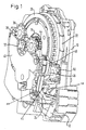
- a sensor carrier plate 10 which receives a sensor housing 12 with a ball 14 inserted therein, is attached to the side of the frame of the belt retractor.
- An actuating disc 16 is mounted rotatably about the axis A of the belt retractor, on which a release pawl 18 is pivotably mounted on a cam 20. The actuating disc 16 activates the locking mechanism when it is rotated in that two load-bearing pawls are driven into locking gearwheels on the belt reel of the belt retractor.
- a clutch disc 22 is connected in a rotationally fixed manner to the belt reel of the belt retractor. It has teeth on its outer circumference, with which a sensor lever 24 interacts, which can be raised by the ball 14 and then brings the release pawl 18 into engagement with the external toothing on the clutch disc 22.
- a control disk 26 is arranged such that it can be rotated about the axis A to a limited extent relative to the belt reel. It is coupled in a rotationally fixed manner to an inertia disk 28. On their mutually facing sides, the clutch disc 22 and the control disc 26 have external teeth 22a and 26a, respectively. These external gears 22a, 26a are identical to one another.
- the actuating disk 16, the clutch disk 22 and the control disk 26 with the inertia disk 28 are accommodated in the interior of a cover 30.
- a planetary gear transmission is arranged on the outside of this cover 30. This consists of a sun gear 32 which is non-rotatably coupled to the belt reel of the belt retractor, two planet gears 34, 36 and an internally toothed ring gear 38 which is formed in a cover cap 40.
- the planet gears 34, 36 are provided with switching cams or switching teeth, by means of which two rocker switches can be actuated.
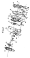
- the first rocker switch 42 can assume two stable switching positions, which are shown in FIGS. 3a and 3b are illustrated. It has two actuating arms 42a, 42b, on which switching cams on the planet wheels strike when a certain angle of rotation of the belt reel is reached. In Fig. 1, such a switching cam is designated 44. When a switching cam strikes one of the actuating arms 42a, 42b, the rocker switch 42 is switched to the other position.
- the rocker switch 42 carries an arcuate switching arm 46 and is coupled to a swivel arm 48, on the free end of which a gear wheel 50 is rotatably mounted.
- the swivel arm 48 keeps the gear wheel 50 out of engagement with the two external toothings 22a, 26a of the clutch disk 22 and the control disk 26.
- the gear wheel 50 engages simultaneously in both external teeth of the clutch disc 22 and the control disc 26, so that these are non-rotatably coupled.
- the switching arm 46 presses against a protruding shoulder of the sensor lever 24 and holds it in a lowered position.
- a second rocker switch 51 can also be pivoted between two stable switching positions, and this rocker switch is also actuated by control cams on the planet gears 34, 36. In one switching position, this rocker switch 51 activates the locking mechanism of the belt retractor by lifting the release pawl 18. In the other switching position, the rocker switch 51 releases the release pawl 18 so that it can be actuated by the ball 14 and the sensor lever 24 in a vehicle-sensitive manner.
- the rocker switch 42 In normal driving operation with the seat belt fastened, the rocker switch 42 is in the starting position shown in FIG. 3a.
- the rocker switch 51 is also in an initial position in which it releases the sensor lever 24. In this state, the locking mechanism of the belt retractor can be activated both in a vehicle-sensitive and in a belt-sensitive manner.
- the switching rocker 42 is switched to the normal position shown in FIG. 3a by a further switching cam on one of the planet gears 34, 36 as soon as a predetermined amount of webbing has been unwound from the belt spool.
- the second rocker switch 51 is used to switch the belt retractor in the so-called automatic locking mode, which is required to secure child seats or loads.
- This operating mode of the belt retractor is activated in that the belt webbing is almost completely pulled off the belt spool and then rolled up again.
- one of the control cams on the planet gears 34, 36 hits an actuating arm on the rocker switch 51 and pivots it so that it lifts the sensor lever 24.
- the webbing is now rewound until it lies against the child seat to be secured or against the load.
- the locking mechanism of the belt retractor is now activated via the actuating disc 16.
- the renewed switching of the rocker switch 51 takes place only when the belt webbing is almost completely wound up again, by pushing a further control cam of the planet gears 34, 36 on the rocker switch 51.
Landscapes
- Engineering & Computer Science (AREA)
- Mechanical Engineering (AREA)
- Automotive Seat Belt Assembly (AREA)
- Air Bags (AREA)
Applications Claiming Priority (2)
| Application Number | Priority Date | Filing Date | Title |
|---|---|---|---|
| DE29608209U DE29608209U1 (de) | 1996-05-06 | 1996-05-06 | Gurtaufroller für Fahrzeugsicherheitsgurte |
| DE29608209U | 1996-05-06 |
Publications (3)
| Publication Number | Publication Date |
|---|---|
| EP0806326A2 true EP0806326A2 (fr) | 1997-11-12 |
| EP0806326A3 EP0806326A3 (fr) | 2000-09-27 |
| EP0806326B1 EP0806326B1 (fr) | 2004-01-02 |
Family
ID=8023618
Family Applications (1)
| Application Number | Title | Priority Date | Filing Date |
|---|---|---|---|
| EP97107356A Expired - Lifetime EP0806326B1 (fr) | 1996-05-06 | 1997-05-05 | Rétracteur pour ceintures de sécurité de véhicule automobile |
Country Status (6)
| Country | Link |
|---|---|
| US (1) | US5794879A (fr) |
| EP (1) | EP0806326B1 (fr) |
| JP (1) | JP3034224B2 (fr) |
| KR (1) | KR970074383A (fr) |
| DE (2) | DE29608209U1 (fr) |
| ES (1) | ES2109908T3 (fr) |
Cited By (1)
| Publication number | Priority date | Publication date | Assignee | Title |
|---|---|---|---|---|
| DE10236858A1 (de) * | 2002-08-07 | 2004-02-26 | Takata-Petri (Ulm) Gmbh | Gurtvorrichtung |
Families Citing this family (24)
| Publication number | Priority date | Publication date | Assignee | Title |
|---|---|---|---|---|
| DE19539284C2 (de) * | 1995-10-21 | 1997-08-21 | Autoliv Dev | Selbstsperrender Gurtaufroller mit Retractor-Umschaltung |
| JP3204911B2 (ja) * | 1996-11-06 | 2001-09-04 | 株式会社東海理化電機製作所 | ウエビング巻取装置 |
| DE29702610U1 (de) * | 1997-02-14 | 1997-06-12 | Trw Occupant Restraint Systems Gmbh, 73551 Alfdorf | Gurtaufroller für einen Fahrzeugsicherheitsgurt |
| DE19732454C2 (de) * | 1997-07-29 | 2002-02-21 | Autoliv Dev | Selbstsperrender Gurtaufroller mit Retractor-Umschaltung |
| US5934596A (en) * | 1998-01-16 | 1999-08-10 | Breed Automative Technology, Inc. | Automatic locking retractor with timing clutch mechanism |
| DE29820086U1 (de) | 1998-11-10 | 1999-04-01 | TRW Occupant Restraint Systems GmbH & Co. KG, 73553 Alfdorf | Gurtaufroller für einen Fahrzeug-Sicherheitsgurt |
| DE19922720A1 (de) * | 1999-05-18 | 2000-11-30 | Trw Repa Gmbh | Gurtaufroller und Verfahren zum Steuern der Funktion eines Insassen-Rückhaltesystems |
| DE29908716U1 (de) * | 1999-05-18 | 1999-09-23 | TRW Occupant Restraint Systems GmbH & Co. KG, 73553 Alfdorf | Gurtaufroller |
| DE19940034C2 (de) | 1999-08-24 | 2001-08-30 | Hs Tech & Design | Gurtaufroller |
| DE19960554A1 (de) * | 1999-09-09 | 2001-03-15 | Takata Europ Gmbh | Sicherheitsgurtvorrichtung für Fahrzeuge |
| DE19957802A1 (de) * | 1999-12-01 | 2001-06-07 | Trw Repa Gmbh | Gurtaufrollersystem |
| JP4785246B2 (ja) * | 1999-12-15 | 2011-10-05 | タカタ株式会社 | シートベルト装置 |
| DE10220043C1 (de) * | 2002-05-04 | 2003-10-23 | Autoliv Dev | Sicherheitsgurtaufroller mit abschaltbarem Fahrzeugsensor |
| JP3947064B2 (ja) * | 2002-08-29 | 2007-07-18 | 株式会社東海理化電機製作所 | ウエビング巻取装置 |
| US20050224623A1 (en) * | 2003-08-26 | 2005-10-13 | Kabushiki Kaisha Tokai-Rika-Denki-Seisakusho | Webbing retractor |
| DE10360032B4 (de) | 2003-12-19 | 2020-06-18 | Trw Automotive Gmbh | Gurtaufroller für einen Fahrzeug-Sicherheitsgurt |
| US7090304B2 (en) * | 2004-07-16 | 2006-08-15 | Trw Vehicle Safety Systems Inc. | Retractor having vehicle sensitive sensor disabling mechanism |
| KR100697237B1 (ko) * | 2006-02-28 | 2007-03-21 | 델파이코리아 주식회사 | 록 캔슬러를 구비한 차량용 시트벨트의 리트랙터 |
| US7637536B2 (en) * | 2006-03-20 | 2009-12-29 | Trw Vehicle Safety Systems Inc. | Retractor having mechanisms for disabling a vehicle sensitive sensor and for preventing webbing withdrawal |
| ATE544638T1 (de) * | 2008-05-27 | 2012-02-15 | Autoliv Dev | Sicherheitsgurtaufroller mit sensorabschaltung |
| DE102009034048B4 (de) * | 2009-07-21 | 2015-10-22 | Key Safety Systems, Inc. | Gurtaufroller für einen Fahrzeugsicherheitsgurt |
| JP5912777B2 (ja) * | 2012-03-30 | 2016-04-27 | 株式会社東海理化電機製作所 | ウェビング巻取装置 |
| EP3127760B1 (fr) * | 2015-08-01 | 2017-11-08 | TRW Automotive GmbH | Enrouleur de ceinture pour une ceinture de securite de vehicule |
| US10737602B2 (en) * | 2018-11-07 | 2020-08-11 | Ford Global Technologies, Llc | Deployable armrest |
Family Cites Families (9)
| Publication number | Priority date | Publication date | Assignee | Title |
|---|---|---|---|---|
| US4164335A (en) * | 1978-04-17 | 1979-08-14 | General Motors Corporation | Automatic locking retractor with lock-up delay |
| US4749142A (en) * | 1985-12-27 | 1988-06-07 | Kabushiki Kaisha Tokai-Rika-Denki-Seisakusho | Webbing retractor |
| US4809926A (en) * | 1986-06-21 | 1989-03-07 | Nippon Seiko Kabushiki Kaisha | Webbing retractor |
| JPS63145747U (fr) * | 1987-03-18 | 1988-09-26 | ||
| DE59008732D1 (de) * | 1990-09-07 | 1995-04-20 | Trw Repa Gmbh | Gurtaufroller mit einer fahrzeugsensitiven und gurtbandsensitiven Sperreinrichtung. |
| DE69202228T2 (de) * | 1991-11-21 | 1995-08-31 | Takata Inc | Sicherheitsgurt-Aufroller mit Klypengeräusch-Beseitigungsvorrichtung. |
| DE9318286U1 (de) * | 1993-11-30 | 1994-02-03 | Trw Repa Gmbh, 73553 Alfdorf | Gurtaufroller für Fahrzeugsicherheitsgurte |
| US5505400A (en) * | 1995-02-15 | 1996-04-09 | Trw Vehicle Safety Systems Inc. | Seat belt retractor with cinch mechanism |
| US5520349A (en) * | 1995-03-23 | 1996-05-28 | Trw Vehicle Safety Systems Inc. | Adjustable automatic locking retractor |
-
1996
- 1996-05-06 DE DE29608209U patent/DE29608209U1/de not_active Expired - Lifetime
-
1997
- 1997-05-02 KR KR1019970016961A patent/KR970074383A/ko not_active Abandoned
- 1997-05-05 ES ES97107356T patent/ES2109908T3/es not_active Expired - Lifetime
- 1997-05-05 DE DE59711162T patent/DE59711162D1/de not_active Expired - Fee Related
- 1997-05-05 EP EP97107356A patent/EP0806326B1/fr not_active Expired - Lifetime
- 1997-05-06 JP JP9115904A patent/JP3034224B2/ja not_active Expired - Fee Related
- 1997-05-06 US US08/851,963 patent/US5794879A/en not_active Expired - Fee Related
Cited By (2)
| Publication number | Priority date | Publication date | Assignee | Title |
|---|---|---|---|---|
| DE10236858A1 (de) * | 2002-08-07 | 2004-02-26 | Takata-Petri (Ulm) Gmbh | Gurtvorrichtung |
| DE10236858B4 (de) * | 2002-08-07 | 2004-06-09 | Takata-Petri (Ulm) Gmbh | Gurtvorrichtung |
Also Published As
| Publication number | Publication date |
|---|---|
| EP0806326B1 (fr) | 2004-01-02 |
| ES2109908T3 (es) | 2004-09-01 |
| EP0806326A3 (fr) | 2000-09-27 |
| JP3034224B2 (ja) | 2000-04-17 |
| ES2109908T1 (es) | 1998-02-01 |
| JPH1044932A (ja) | 1998-02-17 |
| US5794879A (en) | 1998-08-18 |
| DE29608209U1 (de) | 1996-09-05 |
| DE59711162D1 (de) | 2004-02-05 |
| KR970074383A (ko) | 1997-12-10 |
Similar Documents
| Publication | Publication Date | Title |
|---|---|---|
| EP0806326A2 (fr) | Rétracteur pour ceintures de sécurité de véhicule automobile | |
| DE3342478C2 (de) | Gurtaufroller | |
| DE2606293C3 (de) | Vorrichtung zum Zurückziehen und Aufrollen eines Sicherheitsgurtes | |
| DE3732465C2 (de) | Rueckholvorrichtung mit zugentlastung fuer einen sicherheitsgurt | |
| EP0796774A1 (fr) | Rétracteur de ceinture de sécurité comportant un prétentionneur venant en prise avec la bobine d'enroulement | |
| DE4227781C2 (de) | Gurtaufroller mit an der Gurtspule angreifendem Gurtstraffer | |
| EP0655372B1 (fr) | Rétracteur de sangle pour ceintures de sécurité de véhicule | |
| EP0489950B1 (fr) | Fermeture pour ceinture de sécurité de véhicules automobiles | |
| DE10360032B4 (de) | Gurtaufroller für einen Fahrzeug-Sicherheitsgurt | |
| DE29708493U1 (de) | Gurtaufroller mit integriertem Kraftbegrenzer | |
| DE2835853A1 (de) | Sicherheitsgurt-anzugsvorrichtung | |
| DE4132876C2 (fr) | ||
| EP0371288B1 (fr) | Enrouleur pour système de retenue de ceinture de sécurité dans les véhicules automobiles | |
| DE19541430C2 (de) | Elektrisch gesteuerter Sicherheitsgurtaufroller | |
| DE29820086U1 (de) | Gurtaufroller für einen Fahrzeug-Sicherheitsgurt | |
| DE3509254C2 (fr) | ||
| EP0722864A1 (fr) | Dispositif de sûreté lors du transport pour un rétracteur de ceinture | |
| DE2547119C3 (de) | Selbstsperrender Gurtaufroller für Sicherheitsgurte | |
| EP0858936B1 (fr) | Enrouleur pour une ceinture de sécurité de véhicule | |
| EP0543044B1 (fr) | Rétracteur de sangle avec soulagement de traction pour systèmes de retenue par ceinture de sécurité pour véhicules | |
| DE4444655C2 (de) | Sicherheitsgurt-Blockiereinrichtung mit Selbstblockadeverhinderung | |
| DE19602178C1 (de) | Elektrisch gesteuerter Sicherheitsgurtaufroller mit Stromsparschaltung | |
| EP0568820A1 (fr) | Enrouleur de ceinture à réduction de tension pour systèmes de retenue à ceinture de sécurité pour véhicules | |
| DE3306544C2 (fr) | ||
| DE112012002053B4 (de) | Gurtaufroller mit Kindersicherung |
Legal Events
| Date | Code | Title | Description |
|---|---|---|---|
| PUAI | Public reference made under article 153(3) epc to a published international application that has entered the european phase |
Free format text: ORIGINAL CODE: 0009012 |
|
| AK | Designated contracting states |
Kind code of ref document: A2 Designated state(s): DE ES FR GB IT |
|
| ITCL | It: translation for ep claims filed |
Representative=s name: DR. ING. A. RACHELI & C. |
|
| GBC | Gb: translation of claims filed (gb section 78(7)/1977) | ||
| ITCL | It: translation for ep claims filed |
Representative=s name: DR. ING. A. RACHELI & C. |
|
| REG | Reference to a national code |
Ref country code: ES Ref legal event code: BA2A Ref document number: 2109908 Country of ref document: ES Kind code of ref document: T1 |
|
| EL | Fr: translation of claims filed | ||
| RAP1 | Party data changed (applicant data changed or rights of an application transferred) |
Owner name: TRW OCCUPANT RESTRAINT SYSTEMS GMBH & CO. KG |
|
| PUAL | Search report despatched |
Free format text: ORIGINAL CODE: 0009013 |
|
| AK | Designated contracting states |
Kind code of ref document: A3 Designated state(s): DE ES FR GB IT |
|
| RIC1 | Information provided on ipc code assigned before grant |
Free format text: 7B 60R 22/41 A, 7B 60R 22/415 B |
|
| 17P | Request for examination filed |
Effective date: 20010214 |
|
| 17Q | First examination report despatched |
Effective date: 20021114 |
|
| GRAP | Despatch of communication of intention to grant a patent |
Free format text: ORIGINAL CODE: EPIDOSNIGR1 |
|
| GRAS | Grant fee paid |
Free format text: ORIGINAL CODE: EPIDOSNIGR3 |
|
| GRAA | (expected) grant |
Free format text: ORIGINAL CODE: 0009210 |
|
| AK | Designated contracting states |
Kind code of ref document: B1 Designated state(s): DE ES FR GB IT |
|
| REG | Reference to a national code |
Ref country code: GB Ref legal event code: FG4D Free format text: NOT ENGLISH |
|
| REF | Corresponds to: |
Ref document number: 59711162 Country of ref document: DE Date of ref document: 20040205 Kind code of ref document: P |
|
| GBT | Gb: translation of ep patent filed (gb section 77(6)(a)/1977) |
Effective date: 20040303 |
|
| PGFP | Annual fee paid to national office [announced via postgrant information from national office to epo] |
Ref country code: GB Payment date: 20040406 Year of fee payment: 8 |
|
| PGFP | Annual fee paid to national office [announced via postgrant information from national office to epo] |
Ref country code: FR Payment date: 20040503 Year of fee payment: 8 |
|
| PGFP | Annual fee paid to national office [announced via postgrant information from national office to epo] |
Ref country code: ES Payment date: 20040517 Year of fee payment: 8 |
|
| REG | Reference to a national code |
Ref country code: ES Ref legal event code: FG2A Ref document number: 2109908 Country of ref document: ES Kind code of ref document: T3 |
|
| ET | Fr: translation filed | ||
| PLBE | No opposition filed within time limit |
Free format text: ORIGINAL CODE: 0009261 |
|
| STAA | Information on the status of an ep patent application or granted ep patent |
Free format text: STATUS: NO OPPOSITION FILED WITHIN TIME LIMIT |
|
| 26N | No opposition filed |
Effective date: 20041005 |
|
| PG25 | Lapsed in a contracting state [announced via postgrant information from national office to epo] |
Ref country code: IT Free format text: LAPSE BECAUSE OF NON-PAYMENT OF DUE FEES;WARNING: LAPSES OF ITALIAN PATENTS WITH EFFECTIVE DATE BEFORE 2007 MAY HAVE OCCURRED AT ANY TIME BEFORE 2007. THE CORRECT EFFECTIVE DATE MAY BE DIFFERENT FROM THE ONE RECORDED. Effective date: 20050505 Ref country code: GB Free format text: LAPSE BECAUSE OF NON-PAYMENT OF DUE FEES Effective date: 20050505 |
|
| PG25 | Lapsed in a contracting state [announced via postgrant information from national office to epo] |
Ref country code: ES Free format text: LAPSE BECAUSE OF NON-PAYMENT OF DUE FEES Effective date: 20050506 |
|
| GBPC | Gb: european patent ceased through non-payment of renewal fee |
Effective date: 20050505 |
|
| PG25 | Lapsed in a contracting state [announced via postgrant information from national office to epo] |
Ref country code: FR Free format text: LAPSE BECAUSE OF NON-PAYMENT OF DUE FEES Effective date: 20060131 |
|
| REG | Reference to a national code |
Ref country code: FR Ref legal event code: ST Effective date: 20060131 |
|
| PGFP | Annual fee paid to national office [announced via postgrant information from national office to epo] |
Ref country code: DE Payment date: 20060531 Year of fee payment: 10 |
|
| REG | Reference to a national code |
Ref country code: ES Ref legal event code: FD2A Effective date: 20050506 |
|
| PG25 | Lapsed in a contracting state [announced via postgrant information from national office to epo] |
Ref country code: DE Free format text: LAPSE BECAUSE OF NON-PAYMENT OF DUE FEES Effective date: 20071201 |