EP0806326A2 - Retractor for motor vehicle seat belts - Google Patents
Retractor for motor vehicle seat belts Download PDFInfo
- Publication number
- EP0806326A2 EP0806326A2 EP97107356A EP97107356A EP0806326A2 EP 0806326 A2 EP0806326 A2 EP 0806326A2 EP 97107356 A EP97107356 A EP 97107356A EP 97107356 A EP97107356 A EP 97107356A EP 0806326 A2 EP0806326 A2 EP 0806326A2
- Authority
- EP
- European Patent Office
- Prior art keywords
- belt
- switching
- locking mechanism
- belt reel
- belt retractor
- Prior art date
- Legal status (The legal status is an assumption and is not a legal conclusion. Google has not performed a legal analysis and makes no representation as to the accuracy of the status listed.)
- Granted
Links
- 230000000903 blocking effect Effects 0.000 claims abstract description 9
- 230000004913 activation Effects 0.000 claims abstract description 4
- 230000005540 biological transmission Effects 0.000 claims description 3
- 230000000415 inactivating effect Effects 0.000 description 1
- 230000002779 inactivation Effects 0.000 description 1
Images

Classifications
-
- B—PERFORMING OPERATIONS; TRANSPORTING
- B60—VEHICLES IN GENERAL
- B60R—VEHICLES, VEHICLE FITTINGS, OR VEHICLE PARTS, NOT OTHERWISE PROVIDED FOR
- B60R22/00—Safety belts or body harnesses in vehicles
- B60R22/34—Belt retractors, e.g. reels
- B60R22/36—Belt retractors, e.g. reels self-locking in an emergency
- B60R22/415—Belt retractors, e.g. reels self-locking in an emergency with additional means allowing a permanent locking of the retractor during the wearing of the belt
-
- B—PERFORMING OPERATIONS; TRANSPORTING
- B60—VEHICLES IN GENERAL
- B60R—VEHICLES, VEHICLE FITTINGS, OR VEHICLE PARTS, NOT OTHERWISE PROVIDED FOR
- B60R22/00—Safety belts or body harnesses in vehicles
- B60R22/34—Belt retractors, e.g. reels
- B60R22/36—Belt retractors, e.g. reels self-locking in an emergency
- B60R22/41—Belt retractors, e.g. reels self-locking in an emergency with additional means for preventing locking during unwinding under predetermined conditions
Definitions
- the invention relates to a belt retractor for vehicle seat belts, with a belt reel rotatably mounted in a housing, a locking mechanism for blocking the belt reel rotation and a trigger mechanism which has a control disk which can be rotated relative to the belt reel to a limited extent and by means of whose relative rotation to the belt reel the locking mechanism can be activated.
- the trigger mechanism of a belt retractor of this type generally comprises a belt-sensitive part and a vehicle-sensitive part.
- the locking mechanism may be activated unintentionally if the belt strap hits the vehicle seat and the elasticity of the seat padding briefly removes the belt strap. Even when the vehicle is in an inclined position, undesired activation of the locking mechanism can occur after the belt has been removed.
- the trigger mechanism can be used when the webbing is almost completely wound up be deactivated.
- the amount of webbing wound on the belt reel can be felt by a sensor. If the webbing is dirty or the webbing is out of round on the belt reel, however, there are fluctuations in the amount of webbing wound on the belt reel, in which the locking mechanism is deactivated.
- the invention provides a belt retractor whose locking mechanism can be deactivated with high accuracy and reproducibility when a predetermined amount of webbing is wound on the belt reel.
- the belt retractor contains a planetary gear transmission with a sun gear non-rotatably connected to the belt reel, a ring gear fixed to the housing and at least one planet gear which has external teeth and is in engagement with the sun gear and the ring gear and has at least one switching cam; there is also a rocker switch which is pivotally mounted between an initial position and a blocking position and is moved by the switching cam into the blocking position, in which it inactivates the trigger mechanism.
- the rocker switch in its locked position, causes the control disk to be rotatably coupled to the belt spool. Since a relative rotation between the belt reel and the control disk is thus prevented when the rocker switch is in its locked position, belt-sensitive activation cannot take place.
- the rocker switch deactivates a sensor lever of the vehicle-sensitive trigger sensor in its locked position.
- the locking mechanism To activate the belt retractor to immovably attach a child seat to a vehicle seat, one and the same planetary gear is preferably used to activate the child safety device or to deactivate the locking mechanism (with the belt webbing almost completely wound up).
- the belt retractor comprises a belt spool which is rotatably mounted between the legs of a U-shaped frame.
- a locking mechanism that responds to a vehicle-sensitive and belt-strap-sensitive release mechanism and locks the belt spool in a load-bearing manner in an emergency.
- a sensor carrier plate 10 which receives a sensor housing 12 with a ball 14 inserted therein, is attached to the side of the frame of the belt retractor.
- An actuating disc 16 is mounted rotatably about the axis A of the belt retractor, on which a release pawl 18 is pivotably mounted on a cam 20. The actuating disc 16 activates the locking mechanism when it is rotated in that two load-bearing pawls are driven into locking gearwheels on the belt reel of the belt retractor.
- a clutch disc 22 is connected in a rotationally fixed manner to the belt reel of the belt retractor. It has teeth on its outer circumference, with which a sensor lever 24 interacts, which can be raised by the ball 14 and then brings the release pawl 18 into engagement with the external toothing on the clutch disc 22.
- a control disk 26 is arranged such that it can be rotated about the axis A to a limited extent relative to the belt reel. It is coupled in a rotationally fixed manner to an inertia disk 28. On their mutually facing sides, the clutch disc 22 and the control disc 26 have external teeth 22a and 26a, respectively. These external gears 22a, 26a are identical to one another.
- the actuating disk 16, the clutch disk 22 and the control disk 26 with the inertia disk 28 are accommodated in the interior of a cover 30.
- a planetary gear transmission is arranged on the outside of this cover 30. This consists of a sun gear 32 which is non-rotatably coupled to the belt reel of the belt retractor, two planet gears 34, 36 and an internally toothed ring gear 38 which is formed in a cover cap 40.
- the planet gears 34, 36 are provided with switching cams or switching teeth, by means of which two rocker switches can be actuated.
- the first rocker switch 42 can assume two stable switching positions, which are shown in FIGS. 3a and 3b are illustrated. It has two actuating arms 42a, 42b, on which switching cams on the planet wheels strike when a certain angle of rotation of the belt reel is reached. In Fig. 1, such a switching cam is designated 44. When a switching cam strikes one of the actuating arms 42a, 42b, the rocker switch 42 is switched to the other position.
- the rocker switch 42 carries an arcuate switching arm 46 and is coupled to a swivel arm 48, on the free end of which a gear wheel 50 is rotatably mounted.
- the swivel arm 48 keeps the gear wheel 50 out of engagement with the two external toothings 22a, 26a of the clutch disk 22 and the control disk 26.
- the gear wheel 50 engages simultaneously in both external teeth of the clutch disc 22 and the control disc 26, so that these are non-rotatably coupled.
- the switching arm 46 presses against a protruding shoulder of the sensor lever 24 and holds it in a lowered position.
- a second rocker switch 51 can also be pivoted between two stable switching positions, and this rocker switch is also actuated by control cams on the planet gears 34, 36. In one switching position, this rocker switch 51 activates the locking mechanism of the belt retractor by lifting the release pawl 18. In the other switching position, the rocker switch 51 releases the release pawl 18 so that it can be actuated by the ball 14 and the sensor lever 24 in a vehicle-sensitive manner.
- the rocker switch 42 In normal driving operation with the seat belt fastened, the rocker switch 42 is in the starting position shown in FIG. 3a.
- the rocker switch 51 is also in an initial position in which it releases the sensor lever 24. In this state, the locking mechanism of the belt retractor can be activated both in a vehicle-sensitive and in a belt-sensitive manner.
- the switching rocker 42 is switched to the normal position shown in FIG. 3a by a further switching cam on one of the planet gears 34, 36 as soon as a predetermined amount of webbing has been unwound from the belt spool.
- the second rocker switch 51 is used to switch the belt retractor in the so-called automatic locking mode, which is required to secure child seats or loads.
- This operating mode of the belt retractor is activated in that the belt webbing is almost completely pulled off the belt spool and then rolled up again.
- one of the control cams on the planet gears 34, 36 hits an actuating arm on the rocker switch 51 and pivots it so that it lifts the sensor lever 24.
- the webbing is now rewound until it lies against the child seat to be secured or against the load.
- the locking mechanism of the belt retractor is now activated via the actuating disc 16.
- the renewed switching of the rocker switch 51 takes place only when the belt webbing is almost completely wound up again, by pushing a further control cam of the planet gears 34, 36 on the rocker switch 51.
Landscapes
- Engineering & Computer Science (AREA)
- Mechanical Engineering (AREA)
- Automotive Seat Belt Assembly (AREA)
- Air Bags (AREA)
Abstract
Bei einem Gurtaufroller für Fahrzeugsicherheitsgurte, der einer in einem Gehäuse drehbar gelagerten Gurtspule, einen Sperrmechanismus zur Blockierung der Gurtspulendrehung und einen Auslösemechanismus mit einer relativ zur Gurtspule begrenzt verdrehbaren Steuerscheibe (26) aufweist, durch deren Relativdrehung zur Gurtspule der Sperrmechanismus aktivierbar ist, soll eine unbeabsichtigte Aktivierung des Sperrmechanismus verhindert werden. Erreicht wird dies durch, ein Planetenzahnradgetriebe mit einem drehfest an die Gurtspule angeschlossenen Sonnenrad (32), einem gehäusefesten Hohlrad (38) und wenigstens einem Planetenrad (34, 36), das eine Außenverzahnung aufweist und mit dem Sonnenrad (32) und dem Hohlrad (38) in Eingriff steht sowie wenigstens einen Schaltnocken (44) aufweist; und eine zwischen einer Ausgangsstellung und einer Sperrstellung verschwenkbar gelagerte Schaltwippe (42), die durch den Schaltnocken (44) in die Sperrstellung bewegbar ist, in der sie den Auslösemechanismus inaktiviert. <IMAGE>In the case of a belt retractor for vehicle seat belts, which has a belt reel rotatably mounted in a housing, a locking mechanism for blocking the belt reel rotation and a trigger mechanism with a control disk (26) which can be rotated relative to the belt reel to a limited extent, the locking mechanism of which can be activated by the relative rotation thereof relative to the belt reel Activation of the locking mechanism can be prevented. This is achieved by a planetary gear with a sun gear (32) non-rotatably connected to the belt reel, a ring gear fixed to the housing (38) and at least one planet gear (34, 36) which has external teeth and with the sun gear (32) and the ring gear ( 38) is engaged and has at least one switching cam (44); and a rocker switch (42) which is pivotably mounted between a starting position and a blocking position and which can be moved into the blocking position by the switching cam (44), in which it deactivates the triggering mechanism. <IMAGE>
Description
Die Erfindung betrifft einen Gurtaufroller für Fahrzeugsicherheitsgurte, mit einer in einem Gehäuse drehbar gelagerten Gurtspule, einem Sperrmechanismus zur Blockierung der Gurtspulendrehung und einem Auslösemechanismus, der eine relativ zur Gurtspule begrenzt verdrehbare Steuerscheibe aufweist, durch deren Relativdrehung zur Gurtspule der Sperrmechanismus aktiviertbar ist.The invention relates to a belt retractor for vehicle seat belts, with a belt reel rotatably mounted in a housing, a locking mechanism for blocking the belt reel rotation and a trigger mechanism which has a control disk which can be rotated relative to the belt reel to a limited extent and by means of whose relative rotation to the belt reel the locking mechanism can be activated.
Der Auslösemechanismus eines derartigen Gurtaufrollers umfaßt in der Regel einen gurtbandsensitiven und einen fahrzeugsensitiven Teil. Beim Ablegen des Gurtes und Aufrollen des Gurtbandes auf der Gurtspule des Gurtaufrollers kann es zu einer ungewollten Aktivierung des Sperrmechanismus kommen, wenn das Gurtband auf dem Fahrzeugsitz auftrifft und durch die Elastizität der Sitzpolsterung kurzzeitig Gurtband wieder abgezogen wird. Auch bei Schrägstellung des Fahrzeugs kann es nach dem Ablegen des Gurtes zu einer unerwünschten Aktivierung des Sperrmechanismus kommen.The trigger mechanism of a belt retractor of this type generally comprises a belt-sensitive part and a vehicle-sensitive part. When the belt is put down and the belt webbing is rolled onto the belt reel of the belt retractor, the locking mechanism may be activated unintentionally if the belt strap hits the vehicle seat and the elasticity of the seat padding briefly removes the belt strap. Even when the vehicle is in an inclined position, undesired activation of the locking mechanism can occur after the belt has been removed.
Zur Vermeidung einer solchen unerwünschten Sperrung kann der Auslösemechanismus bei nahezu vollständig aufgewickeltem Gurtband inaktiviert werden. Die auf der Gurtspule aufgewickelte Gurtbandmenge kann durch einen Fühler ertastet werden. Bei verschmutztem Gurtband oder unrundem Gurtbandwickel auf der Gurtspule ergeben sich jedoch Schwankungen hinsichtlich der auf der Gurtspule aufgewickelten Gurtbandmenge, bei der die Inaktivierung des Sperrmechanismus geschieht.To avoid such an undesirable locking mechanism, the trigger mechanism can be used when the webbing is almost completely wound up be deactivated. The amount of webbing wound on the belt reel can be felt by a sensor. If the webbing is dirty or the webbing is out of round on the belt reel, however, there are fluctuations in the amount of webbing wound on the belt reel, in which the locking mechanism is deactivated.
Durch die Erfindung wird ein Gurtaufroller zur Verfügung gestellt, dessen Sperrmechanismus mit hoher Genauigkeit und Reproduzierbarkeit inaktiviert werden kann, wenn eine vorherbestimmte Gurtbandmenge auf der Gurtspule aufgewickelt ist. Gemäß der Erfindung enthält der Gurtaufroller ein Planetenzahnradgetriebe mit einem drehfest an die Gurtspule angeschlossenen Sonnenrad, einem gehäusefesten Hohlrad und wenigstens einem Planetenrad, das eine Außenverzahnung aufweist und mit dem Sonnenrad und dem Hohlrad in Eingriff steht sowie wenigstens einen Schaltnocken aufweist; ferner ist eine Schaltwippe vorhanden, die zwischen einer Ausgangstellung und einer Sperrstellung schwenkbar gelagert ist und durch den Schaltnocken in die Sperrstellung bewegt wird, in welcher sie den Auslösemechanismus inaktiviert. Durch die Verwendung eines Planetenradgetriebes anstelle eines Gurtbandfühlers wird nicht der mit Schwankungen behaftete Außendurchmesser des Gurtbandwickels, sondern der Drehwinkel der Gurtspule abgefragt und als Kriterium zur Inaktivierung des Auslösemechanismus verwendet.The invention provides a belt retractor whose locking mechanism can be deactivated with high accuracy and reproducibility when a predetermined amount of webbing is wound on the belt reel. According to the invention, the belt retractor contains a planetary gear transmission with a sun gear non-rotatably connected to the belt reel, a ring gear fixed to the housing and at least one planet gear which has external teeth and is in engagement with the sun gear and the ring gear and has at least one switching cam; there is also a rocker switch which is pivotally mounted between an initial position and a blocking position and is moved by the switching cam into the blocking position, in which it inactivates the trigger mechanism. By using a planetary gearbox instead of a webbing sensor, it is not the fluctuating outside diameter of the webbing reel that is queried, but the angle of rotation of the belt reel and used as a criterion for inactivating the release mechanism.
Zur Inaktivierung des gurtbandsensitiven Teils des Auslösemechanismus bewirkt gemäß der bevorzugten Ausführüngsform die Schaltwippe in ihrer Sperrstellung eine drehfeste Kopplung der Steuerscheibe mit der Gurtspule. Da somit eine Relativdrehung zwischen Gurtspule und Steuerscheibe unterbunden ist, wenn sich die Schaltwippe in ihrer Sperrstellung befindet, kann keine gurtbandsensitive Auslösung erfolgen.In order to inactivate the belt-strap-sensitive part of the release mechanism, according to the preferred embodiment, the rocker switch, in its locked position, causes the control disk to be rotatably coupled to the belt spool. Since a relative rotation between the belt reel and the control disk is thus prevented when the rocker switch is in its locked position, belt-sensitive activation cannot take place.
Für den fahrzeugsensitiven Teil des Auslösemechanismus ist bei der bevorzugten Ausführungsform vorgesehen, daß die Schaltwippe in ihrer Sperrstellung einen Sensorhebel des fahrzeugsensitiven Auslösesensors inaktiviert.For the vehicle-sensitive part of the trigger mechanism it is provided in the preferred embodiment that the rocker switch deactivates a sensor lever of the vehicle-sensitive trigger sensor in its locked position.
Wenn der Gurtaufroller auch mit einer Kindersicherung ausgestattet ist, die in an sich bekannter Weise dazu dient, den Sperrmechanismus des Gurtaufrollers zu aktivieren, um einen Kindersitz unverrückbar an einem Fahrzeugsitz festzulegen, wird vorzugsweise ein und dasselbe Planetenradgetriebe verwendet, um die Kindersicherung zu aktivieren oder den Sperrmechanismus (bei nahezu vollständig aufgewickeltem Gurtband) zu inaktivieren.If the belt retractor is also equipped with a child lock, which serves in a manner known per se, the locking mechanism To activate the belt retractor to immovably attach a child seat to a vehicle seat, one and the same planetary gear is preferably used to activate the child safety device or to deactivate the locking mechanism (with the belt webbing almost completely wound up).
Weitere Merkmale und Vorteile der Erfindung ergeben sich aus der folgenden Beschreibung einer bevorzugten Ausführungsform und aus der Zeichnung, auf die Bezug genommen wird. In der Zeichnung zeigen:
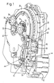
- Fig. 1 eine aufgeschnittene Perspektivansicht der Steuerseite eines Gurtaufrollers;
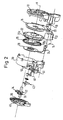
- Fig. 2 eine Explosionsansicht des Steuerteils des Gurtaufrollers; und
- Fig. 3a sowie 3b die Schaltzustände einer Inaktivierungseinrichtung für den Sperrmechanismus des Gurtaufrollers.
- Figure 1 is a cut perspective view of the control side of a belt retractor.
- Fig. 2 is an exploded view of the control part of the retractor; and
- 3a and 3b, the switching states of an inactivation device for the locking mechanism of the belt retractor.
Von dem erfindungsgemäßen Gurtaufroller wird hier nur die sogenannte Steuerseite beschrieben, da alle übrigen Bestandteile herkömmlich ausgebildet sind. Insbesondere umfaßt der Gurtaufroller eine Gurtspule, die zwischen den Schenkeln eines U-förmigen Rahmens drehbar gelagert ist. Ferner ist ein Sperrmechanismus vorhanden, der auf einen fahrzeugsensitiven und gurtbandsensitiven Auslösemechanismus anspricht und die Gurtspule im Notfall lasttragend sperrt.Of the belt retractor according to the invention, only the so-called control side is described here, since all other components are of conventional design. In particular, the belt retractor comprises a belt spool which is rotatably mounted between the legs of a U-shaped frame. There is also a locking mechanism that responds to a vehicle-sensitive and belt-strap-sensitive release mechanism and locks the belt spool in a load-bearing manner in an emergency.
Seitlich an den Rahmen des Gurtaufrollers angesetzt ist eine Sensor-Trägerplatte 10, die ein Sensorgehäuse 12 mit einer darin eingelegten Kugel 14 aufnimmt. Um die Achse A des Gurtaufrollers verdrehbar gelagert ist eine Betätigungsscheibe 16, an der eine Auslöseklinke 18 an einem Nocken 20 schwenkbar gelagert ist. Die Betätigungsscheibe 16 aktiviert bei ihrer Drehung den Sperrmechanismus, indem zwei lasttragende Klinken in Sperrzahnräder an der Gurtspule des Gurtaufrollers eingesteuert werden.A
An die Gurtspule des Gurtaufrollers ist eine Kupplungsscheibe 22 drehfest angeschlossen. Sie trägt an ihrem Außenumfang eine Verzahnung, mit der ein Sensorhebel 24 zusammenwirkt, der durch die Kugel 14 angehoben werden kann und dann die Auslöseklinke 18 mit der Außenverzahnung an der Kupplungsscheibe 22 in Eingriff bringt.A
Relativ zur Gurtspule begrenzt verdrehbar um die Achse A angeordnet ist eine Steuerscheibe 26. Sie ist mit einer Trägheitsscheibe 28 drehfest gekoppelt. Auf ihren einander zugewandten Seiten tragen die Kupplungsscheibe 22 und die Steuerscheibe 26 eine Außenverzahnung 22a bzw. 26a. Diese Außenverzahnungen 22a, 26a sind einander gleich ausgebildet.A
Die Betätigungsscheibe 16, die Kupplungsscheibe 22 und die Steuerscheibe 26 mit der Trägheitsscheibe 28 sind im Inneren einer Abdeckung 30 aufgenommen. An der Außenseite dieser Abdeckung 30 ist ein Planetenzahnradgetriebe angeordnet. Dieses besteht aus einem drehfest mit der Gurtspule des Gurtaufrollers gekoppelten Sonnenrad 32, zwei Planetenrädern 34, 36 und einem innenverzahnten Hohlrad 38, das in einer Abdeckkappe 40 gebildet ist.The actuating
Die Planetenräder 34, 36 sind mit Schaltnocken oder Schaltzähnen versehen, durch die zwei Schaltwippen betätigbar sind.The
Die erste Schaltwippe 42 kann zwei stabile Schaltstellungen einnehmen, die in den Fign. 3a und 3b veranschaulicht sind. Sie weist zwei Betätigungsarme 42a, 42b auf, an denen Schaltnocken an den Planetenrädern bei Erreichen eines bestimmten Drehwinkels der Gurtspule anstoßen. In Fig. 1 ist ein solcher Schaltnocken mit 44 bezeichnet. Beim Anstoßen eines Schaltnockens auf einem der Betätigungsarme 42a, 42b wird die Schaltwippe 42 in die jeweils andere Stellung umgeschaltet.The
Die Schaltwippe 42 trägt einen bogenförmigen Schaltarm 46 und ist mit einem Schwenkarm 48 gekoppelt, an dessen freiem Ende ein Zahnrad 50 drehbar gelagert ist. Bei der in Fig. 3a gezeigten Schaltstellung der Schaltwippe 42 hält der Schwenkarm 48 das Zahnrad 50 außer Eingriff mit den beiden Außenverzahnungen 22a, 26a der Kupplungsscheibe 22 und der Steuerscheibe 26. Bei der in Fig. 3 gezeigten Schaltstellung der Schaltwippe 42 greift das Zahnrad 50 gleichzeitig in beide Außenverzahnungen der Kupplungsscheibe 22 und der Steuerscheibe 26, so daß diese drehfest miteinander gekoppelt sind. Gleichzeitig drückt der Schaltarm 46 gegen einen hochragenden Ansatz des Sensorhebels 24 und halt diesen in einer abgesenkten Stellung.The
Eine zweite Schaltwippe 51 ist gleichfalls zwischen zwei stabilen Schaltstellungen verschwenkbar, und auch diese Schaltwippe wird durch Steuernocken an den Planetenrädern 34, 36 betätigt. In der einen Schaltstellung aktiviert diese Schaltwippe 51 den Sperrmechanismus des Gurtaufrollers, indem sie die Auslöseklinke 18 anhebt. In der anderen Schaltstellung gibt die Schaltwippe 51 die Auslöseklinke 18 frei, so daß diese fahrzeugsensitiv durch die Kugel 14 und den Sensorhebel 24 betätigbar ist.A
Im normalen Fahrbetrieb bei angelegtem Sicherheitsgurt befindet sich die Schaltwippe 42 in der in Fig. 3a gezeigten Ausgangsstellung. Die Schaltwippe 51 befindet sich gleichfalls in einer Ausgangsstellung, in welcher sie den Sensorhebel 24 freigibt. Der Sperrmechanismus des Gurtaufrollers ist in diesem Zustand sowohl fahrzeugsensitiv als auch gurtbandsensitiv aktivierbar.In normal driving operation with the seat belt fastened, the
Nach dem Ablegen des Gurtbandes wird dieses auf der Gurtspule aufgerollt. Bei einem bestimmten Drehwinkel der Gurtspule, der dem nahezu vollständig aufgewickelten Gurtband entspricht, stößt der Schaltnocken 44 gegen den Betätigungsarm 42a der Schaltwippe 42, so daß diese in die in Fig. 3b gezeigte Schaltstellung verschwenkt wird. In dieser Stellung sind die Kupplungsscheibe 22 und die Steuerscheibe 26 durch das Zahnrad 50 drehfest miteinander gekoppelt. Eine gurtsensitive Auslösung des Sperrmechanismus ist somit unterbunden. Auch eine fahrzeugsensitive Auslösung ist unterbunden, da der Sensorhebel 24 durch den Schaltarm 46 niedergehalten wird. Eine unbeabsichtigte Sperrung der Gurtspule in diesem Zustand wird somit zuverlässig verhindert.After removing the webbing, it is rolled up on the belt spool. At a certain angle of rotation of the belt reel, which corresponds to the almost completely wound webbing, the switching cam 44 abuts the actuating
Die Umschaltung der Schaltwippe 42 in die normale, in Fig. 3a gezeigte Stellung erfolgt durch einen weiteren Schaltnocken an einem der Planetenräder 34, 36, sobald eine vorbestimmte Gurtbandmenge von der Gurtspule abgewickelt ist.The switching
Die zweite Schaltwippe 51 dient der Umschaltung des Gurtaufrollers in den sogenannten automatisch sperrenden Modus, der zur Sicherung von Kindersitzen oder Lasten benötigt wird. Dieser Betriebsmodus des Gurtaufrollers wird aktiviert, indem Gurtband von der Gurtspule nahezu vollständig abgezogen und dann wieder aufgerollt wird. Bei diesem Vorgang trifft einer der Steuernocken an den Planetenrädern 34, 36 auf einem Betätigungsarm an der Schaltwippe 51 und verschwenkt diese, damit sie den Sensorhebel 24 anhebt. Das Gurtband wird nun wieder aufgewickelt, bis es am zu sichernden Kindersitz oder an der Last anliegt. Beim Versuch, Gurtband abzuwickeln, wird nun der Sperrmechanismus des Gurtaufrollers über die Betätigungsscheibe 16 aktiviert. Die erneute Umschaltung der Schaltwippe 51 erfolgt erst, wenn das Gurtband wieder nahezu vollständig aufgewickelt ist, durch Anstoßen eines weiteren Steuernockens der Planetenräder 34, 36 an der Schaltwippe 51.The
Claims (6)
gekennzeichnet durch:
marked by:
Applications Claiming Priority (2)
| Application Number | Priority Date | Filing Date | Title |
|---|---|---|---|
| DE29608209U DE29608209U1 (en) | 1996-05-06 | 1996-05-06 | Belt retractors for vehicle seat belts |
| DE29608209U | 1996-05-06 |
Publications (3)
| Publication Number | Publication Date |
|---|---|
| EP0806326A2 true EP0806326A2 (en) | 1997-11-12 |
| EP0806326A3 EP0806326A3 (en) | 2000-09-27 |
| EP0806326B1 EP0806326B1 (en) | 2004-01-02 |
Family
ID=8023618
Family Applications (1)
| Application Number | Title | Priority Date | Filing Date |
|---|---|---|---|
| EP97107356A Expired - Lifetime EP0806326B1 (en) | 1996-05-06 | 1997-05-05 | Retractor for motor vehicle seat belts |
Country Status (6)
| Country | Link |
|---|---|
| US (1) | US5794879A (en) |
| EP (1) | EP0806326B1 (en) |
| JP (1) | JP3034224B2 (en) |
| KR (1) | KR970074383A (en) |
| DE (2) | DE29608209U1 (en) |
| ES (1) | ES2109908T3 (en) |
Cited By (1)
| Publication number | Priority date | Publication date | Assignee | Title |
|---|---|---|---|---|
| DE10236858A1 (en) * | 2002-08-07 | 2004-02-26 | Takata-Petri (Ulm) Gmbh | belt device |
Families Citing this family (23)
| Publication number | Priority date | Publication date | Assignee | Title |
|---|---|---|---|---|
| DE19539284C2 (en) * | 1995-10-21 | 1997-08-21 | Autoliv Dev | Self-locking belt retractor with retractor switchover |
| JP3204911B2 (en) * | 1996-11-06 | 2001-09-04 | 株式会社東海理化電機製作所 | Webbing take-up device |
| DE29702610U1 (en) * | 1997-02-14 | 1997-06-12 | Trw Repa Gmbh | Belt retractor for a vehicle seat belt |
| DE19732454C2 (en) * | 1997-07-29 | 2002-02-21 | Autoliv Dev | Self-locking belt retractor with retractor switchover |
| US5934596A (en) * | 1998-01-16 | 1999-08-10 | Breed Automative Technology, Inc. | Automatic locking retractor with timing clutch mechanism |
| DE19922720A1 (en) * | 1999-05-18 | 2000-11-30 | Trw Repa Gmbh | Belt spooler for vehicle occupant restraint system has incremental counter coupled to belt calibrated using control plate sensor so counter state represents absolute rotation angle of spool |
| DE29908716U1 (en) * | 1999-05-18 | 1999-09-23 | Trw Repa Gmbh | Belt retractor |
| DE19940034C2 (en) * | 1999-08-24 | 2001-08-30 | Hs Tech & Design | Belt retractor |
| DE19960554A1 (en) * | 1999-09-09 | 2001-03-15 | Takata Europ Gmbh | Safety belt system for motor vehicles has cam ring with two angled sections , one for ratchet operation, the other for additional function |
| DE19957802A1 (en) * | 1999-12-01 | 2001-06-07 | Trw Repa Gmbh | Belt retractor system |
| JP4785246B2 (en) | 1999-12-15 | 2011-10-05 | タカタ株式会社 | Seat belt device |
| DE10220043C1 (en) * | 2002-05-04 | 2003-10-23 | Autoliv Dev | Self-locking inertia reel for automobile seatbelt, with switching between emergency locking retractor mode and automatic locking retractor mode |
| JP3947064B2 (en) * | 2002-08-29 | 2007-07-18 | 株式会社東海理化電機製作所 | Webbing take-up device |
| US20050224623A1 (en) * | 2003-08-26 | 2005-10-13 | Kabushiki Kaisha Tokai-Rika-Denki-Seisakusho | Webbing retractor |
| DE10360032B4 (en) * | 2003-12-19 | 2020-06-18 | Trw Automotive Gmbh | Belt retractor for a vehicle seat belt |
| US7090304B2 (en) * | 2004-07-16 | 2006-08-15 | Trw Vehicle Safety Systems Inc. | Retractor having vehicle sensitive sensor disabling mechanism |
| KR100697237B1 (en) * | 2006-02-28 | 2007-03-21 | 델파이코리아 주식회사 | Seat belt retractor for a vehicle provided with a lock canceller |
| US7637536B2 (en) * | 2006-03-20 | 2009-12-29 | Trw Vehicle Safety Systems Inc. | Retractor having mechanisms for disabling a vehicle sensitive sensor and for preventing webbing withdrawal |
| US8672252B2 (en) * | 2008-05-27 | 2014-03-18 | Autoliv Development Ab | Seat belt retractor with sensor cutoff |
| DE102009034048B4 (en) * | 2009-07-21 | 2015-10-22 | Key Safety Systems, Inc. | Belt retractor for a vehicle seat belt |
| JP5912777B2 (en) * | 2012-03-30 | 2016-04-27 | 株式会社東海理化電機製作所 | Webbing take-up device |
| EP3127760B1 (en) * | 2015-08-01 | 2017-11-08 | TRW Automotive GmbH | Belt roller for a vehicle seatbelt |
| US10737602B2 (en) * | 2018-11-07 | 2020-08-11 | Ford Global Technologies, Llc | Deployable armrest |
Citations (5)
| Publication number | Priority date | Publication date | Assignee | Title |
|---|---|---|---|---|
| DE8803659U1 (en) * | 1987-03-18 | 1988-07-07 | Takata Corp., Tokio/Tokyo, Jp | |
| US4809926A (en) * | 1986-06-21 | 1989-03-07 | Nippon Seiko Kabushiki Kaisha | Webbing retractor |
| EP0473832A1 (en) * | 1990-09-07 | 1992-03-11 | TRW Occupant Restraint Systems GmbH | Belt retractor with a vehicle and belt responsive locking device |
| EP0543520A1 (en) * | 1991-11-21 | 1993-05-26 | Takata Inc. | Seat belt retractor having rattle suppression mechanism |
| DE9318286U1 (en) * | 1993-11-30 | 1994-02-03 | Trw Repa Gmbh | Belt retractors for vehicle seat belts |
Family Cites Families (4)
| Publication number | Priority date | Publication date | Assignee | Title |
|---|---|---|---|---|
| US4164335A (en) * | 1978-04-17 | 1979-08-14 | General Motors Corporation | Automatic locking retractor with lock-up delay |
| US4749142A (en) * | 1985-12-27 | 1988-06-07 | Kabushiki Kaisha Tokai-Rika-Denki-Seisakusho | Webbing retractor |
| US5505400A (en) * | 1995-02-15 | 1996-04-09 | Trw Vehicle Safety Systems Inc. | Seat belt retractor with cinch mechanism |
| US5520349A (en) * | 1995-03-23 | 1996-05-28 | Trw Vehicle Safety Systems Inc. | Adjustable automatic locking retractor |
-
1996
- 1996-05-06 DE DE29608209U patent/DE29608209U1/en not_active Expired - Lifetime
-
1997
- 1997-05-02 KR KR1019970016961A patent/KR970074383A/en active IP Right Grant
- 1997-05-05 ES ES97107356T patent/ES2109908T3/en not_active Expired - Lifetime
- 1997-05-05 DE DE59711162T patent/DE59711162D1/en not_active Expired - Fee Related
- 1997-05-05 EP EP97107356A patent/EP0806326B1/en not_active Expired - Lifetime
- 1997-05-06 JP JP9115904A patent/JP3034224B2/en not_active Expired - Fee Related
- 1997-05-06 US US08/851,963 patent/US5794879A/en not_active Expired - Fee Related
Patent Citations (5)
| Publication number | Priority date | Publication date | Assignee | Title |
|---|---|---|---|---|
| US4809926A (en) * | 1986-06-21 | 1989-03-07 | Nippon Seiko Kabushiki Kaisha | Webbing retractor |
| DE8803659U1 (en) * | 1987-03-18 | 1988-07-07 | Takata Corp., Tokio/Tokyo, Jp | |
| EP0473832A1 (en) * | 1990-09-07 | 1992-03-11 | TRW Occupant Restraint Systems GmbH | Belt retractor with a vehicle and belt responsive locking device |
| EP0543520A1 (en) * | 1991-11-21 | 1993-05-26 | Takata Inc. | Seat belt retractor having rattle suppression mechanism |
| DE9318286U1 (en) * | 1993-11-30 | 1994-02-03 | Trw Repa Gmbh | Belt retractors for vehicle seat belts |
Cited By (2)
| Publication number | Priority date | Publication date | Assignee | Title |
|---|---|---|---|---|
| DE10236858A1 (en) * | 2002-08-07 | 2004-02-26 | Takata-Petri (Ulm) Gmbh | belt device |
| DE10236858B4 (en) * | 2002-08-07 | 2004-06-09 | Takata-Petri (Ulm) Gmbh | belt device |
Also Published As
| Publication number | Publication date |
|---|---|
| ES2109908T3 (en) | 2004-09-01 |
| US5794879A (en) | 1998-08-18 |
| ES2109908T1 (en) | 1998-02-01 |
| KR970074383A (en) | 1997-12-10 |
| JP3034224B2 (en) | 2000-04-17 |
| DE29608209U1 (en) | 1996-09-05 |
| EP0806326B1 (en) | 2004-01-02 |
| JPH1044932A (en) | 1998-02-17 |
| DE59711162D1 (en) | 2004-02-05 |
| EP0806326A3 (en) | 2000-09-27 |
Similar Documents
| Publication | Publication Date | Title |
|---|---|---|
| EP0806326A2 (en) | Retractor for motor vehicle seat belts | |
| DE3342478C2 (en) | Belt retractor | |
| DE2606293C3 (en) | Device for retracting and rolling up a seat belt | |
| DE3732465C2 (en) | RETURN DEVICE WITH TENSION RELIEF FOR A SAFETY BELT | |
| EP0796774A1 (en) | Belt retractor with tensioner operating on the belt spool | |
| DE4227781C2 (en) | Belt retractor with belt tensioner acting on the belt reel | |
| EP0655372B1 (en) | Belt retractor for vehicle safety belts | |
| EP0489950B1 (en) | Lock for automobile safety belt | |
| DE2835853A1 (en) | SEAT BELT TIGHTENING DEVICE | |
| DE10360032B4 (en) | Belt retractor for a vehicle seat belt | |
| EP0371288B1 (en) | Webbing retractor for seat belt locking mechanisms in automotive vehicles | |
| DE4132876C2 (en) | ||
| DE10321218A1 (en) | Seat belt roller, has drive wheel with teeth cooperating with pawl in end of belt spool | |
| EP1209047A1 (en) | Belt retractor for a vehicle seat belt | |
| DE3632066A1 (en) | DEVICE FOR ELIMINATING TENSION FOR A RETRACTOR DEVICE OF A SAFETY BELT OF A VEHICLE | |
| DE19541430C2 (en) | Electrically controlled seat belt retractor | |
| DE102009034048A1 (en) | Belt retractor for a vehicle seat belt | |
| EP0722864A1 (en) | Transport security device for a belt retractor | |
| DE2547119C3 (en) | Self-locking belt retractor for seat belts | |
| EP0858936B1 (en) | Retractor for a vehicle seat belt | |
| EP0543044B1 (en) | Belt retractor with strain relief for safety belt restraint systems for vehicles | |
| DE3509254C2 (en) | ||
| EP0568820B1 (en) | Tension relieved belt retractor for safety belt restraint systems in vehicles | |
| DE102004022401B4 (en) | Belt retractor with pre-tensioner drive | |
| DE3306544C2 (en) |
Legal Events
| Date | Code | Title | Description |
|---|---|---|---|
| PUAI | Public reference made under article 153(3) epc to a published international application that has entered the european phase |
Free format text: ORIGINAL CODE: 0009012 |
|
| AK | Designated contracting states |
Kind code of ref document: A2 Designated state(s): DE ES FR GB IT |
|
| ITCL | It: translation for ep claims filed |
Representative=s name: DR. ING. A. RACHELI & C. |
|
| GBC | Gb: translation of claims filed (gb section 78(7)/1977) | ||
| ITCL | It: translation for ep claims filed |
Representative=s name: DR. ING. A. RACHELI & C. |
|
| REG | Reference to a national code |
Ref country code: ES Ref legal event code: BA2A Ref document number: 2109908 Country of ref document: ES Kind code of ref document: T1 |
|
| EL | Fr: translation of claims filed | ||
| RAP1 | Party data changed (applicant data changed or rights of an application transferred) |
Owner name: TRW OCCUPANT RESTRAINT SYSTEMS GMBH & CO. KG |
|
| PUAL | Search report despatched |
Free format text: ORIGINAL CODE: 0009013 |
|
| AK | Designated contracting states |
Kind code of ref document: A3 Designated state(s): DE ES FR GB IT |
|
| RIC1 | Information provided on ipc code assigned before grant |
Free format text: 7B 60R 22/41 A, 7B 60R 22/415 B |
|
| 17P | Request for examination filed |
Effective date: 20010214 |
|
| 17Q | First examination report despatched |
Effective date: 20021114 |
|
| GRAP | Despatch of communication of intention to grant a patent |
Free format text: ORIGINAL CODE: EPIDOSNIGR1 |
|
| GRAS | Grant fee paid |
Free format text: ORIGINAL CODE: EPIDOSNIGR3 |
|
| GRAA | (expected) grant |
Free format text: ORIGINAL CODE: 0009210 |
|
| AK | Designated contracting states |
Kind code of ref document: B1 Designated state(s): DE ES FR GB IT |
|
| REG | Reference to a national code |
Ref country code: GB Ref legal event code: FG4D Free format text: NOT ENGLISH |
|
| REF | Corresponds to: |
Ref document number: 59711162 Country of ref document: DE Date of ref document: 20040205 Kind code of ref document: P |
|
| GBT | Gb: translation of ep patent filed (gb section 77(6)(a)/1977) |
Effective date: 20040303 |
|
| PGFP | Annual fee paid to national office [announced via postgrant information from national office to epo] |
Ref country code: GB Payment date: 20040406 Year of fee payment: 8 |
|
| PGFP | Annual fee paid to national office [announced via postgrant information from national office to epo] |
Ref country code: FR Payment date: 20040503 Year of fee payment: 8 |
|
| PGFP | Annual fee paid to national office [announced via postgrant information from national office to epo] |
Ref country code: ES Payment date: 20040517 Year of fee payment: 8 |
|
| REG | Reference to a national code |
Ref country code: ES Ref legal event code: FG2A Ref document number: 2109908 Country of ref document: ES Kind code of ref document: T3 |
|
| ET | Fr: translation filed | ||
| PLBE | No opposition filed within time limit |
Free format text: ORIGINAL CODE: 0009261 |
|
| STAA | Information on the status of an ep patent application or granted ep patent |
Free format text: STATUS: NO OPPOSITION FILED WITHIN TIME LIMIT |
|
| 26N | No opposition filed |
Effective date: 20041005 |
|
| PG25 | Lapsed in a contracting state [announced via postgrant information from national office to epo] |
Ref country code: IT Free format text: LAPSE BECAUSE OF NON-PAYMENT OF DUE FEES;WARNING: LAPSES OF ITALIAN PATENTS WITH EFFECTIVE DATE BEFORE 2007 MAY HAVE OCCURRED AT ANY TIME BEFORE 2007. THE CORRECT EFFECTIVE DATE MAY BE DIFFERENT FROM THE ONE RECORDED. Effective date: 20050505 Ref country code: GB Free format text: LAPSE BECAUSE OF NON-PAYMENT OF DUE FEES Effective date: 20050505 |
|
| PG25 | Lapsed in a contracting state [announced via postgrant information from national office to epo] |
Ref country code: ES Free format text: LAPSE BECAUSE OF NON-PAYMENT OF DUE FEES Effective date: 20050506 |
|
| GBPC | Gb: european patent ceased through non-payment of renewal fee |
Effective date: 20050505 |
|
| PG25 | Lapsed in a contracting state [announced via postgrant information from national office to epo] |
Ref country code: FR Free format text: LAPSE BECAUSE OF NON-PAYMENT OF DUE FEES Effective date: 20060131 |
|
| REG | Reference to a national code |
Ref country code: FR Ref legal event code: ST Effective date: 20060131 |
|
| PGFP | Annual fee paid to national office [announced via postgrant information from national office to epo] |
Ref country code: DE Payment date: 20060531 Year of fee payment: 10 |
|
| REG | Reference to a national code |
Ref country code: ES Ref legal event code: FD2A Effective date: 20050506 |
|
| PG25 | Lapsed in a contracting state [announced via postgrant information from national office to epo] |
Ref country code: DE Free format text: LAPSE BECAUSE OF NON-PAYMENT OF DUE FEES Effective date: 20071201 |