EP0858936B1 - Enrouleur pour une ceinture de sécurité de véhicule - Google Patents
Enrouleur pour une ceinture de sécurité de véhicule Download PDFInfo
- Publication number
- EP0858936B1 EP0858936B1 EP98101373A EP98101373A EP0858936B1 EP 0858936 B1 EP0858936 B1 EP 0858936B1 EP 98101373 A EP98101373 A EP 98101373A EP 98101373 A EP98101373 A EP 98101373A EP 0858936 B1 EP0858936 B1 EP 0858936B1
- Authority
- EP
- European Patent Office
- Prior art keywords
- switch
- belt
- rocker
- belt retractor
- set forth
- Prior art date
- Legal status (The legal status is an assumption and is not a legal conclusion. Google has not performed a legal analysis and makes no representation as to the accuracy of the status listed.)
- Expired - Lifetime
Links
Images


Classifications
-
- B—PERFORMING OPERATIONS; TRANSPORTING
- B60—VEHICLES IN GENERAL
- B60R—VEHICLES, VEHICLE FITTINGS, OR VEHICLE PARTS, NOT OTHERWISE PROVIDED FOR
- B60R22/00—Safety belts or body harnesses in vehicles
- B60R22/34—Belt retractors, e.g. reels
- B60R22/36—Belt retractors, e.g. reels self-locking in an emergency
- B60R22/415—Belt retractors, e.g. reels self-locking in an emergency with additional means allowing a permanent locking of the retractor during the wearing of the belt
-
- B—PERFORMING OPERATIONS; TRANSPORTING
- B60—VEHICLES IN GENERAL
- B60R—VEHICLES, VEHICLE FITTINGS, OR VEHICLE PARTS, NOT OTHERWISE PROVIDED FOR
- B60R21/00—Arrangements or fittings on vehicles for protecting or preventing injuries to occupants or pedestrians in case of accidents or other traffic risks
- B60R21/01—Electrical circuits for triggering passive safety arrangements, e.g. airbags, safety belt tighteners, in case of vehicle accidents or impending vehicle accidents
- B60R21/015—Electrical circuits for triggering passive safety arrangements, e.g. airbags, safety belt tighteners, in case of vehicle accidents or impending vehicle accidents including means for detecting the presence or position of passengers, passenger seats or child seats, and the related safety parameters therefor, e.g. speed or timing of airbag inflation in relation to occupant position or seat belt use
- B60R21/01512—Passenger detection systems
- B60R21/01544—Passenger detection systems detecting seat belt parameters, e.g. length, tension or height-adjustment
Definitions
- the invention relates to a belt retractor for one Vehicle seat belt, with a rotatably mounted in a housing Belt reel, a webbing wound on the belt reel, one Locking mechanism for blocking the belt spool rotation, one Planetary gear transmission with a rotationally fixed to the belt reel connected sun gear, a housing-fixed ring gear and wengistens a planet gear, which has external teeth, and an electrical Switch unit for determining the application state based on the length of the removed webbing, the switching unit being electrically connected a control unit for activating a gas generator and one through the movement of the planet gear actuated shift lever comprises.
- a generic belt retractor is from DE-A-296 05 803.3 known.
- a planet gear of this known belt retractor is with a Lever via a pinion rotatably mounted on the belt reel shaft coupled so that the pinion when rotating the planet gear around Sun gear turns.
- a toothing engages in the toothing of the pinion a rack.
- the adjustment of the rack is used to determine the Application state, d. H. whether the occupant is belted or not scanned, from a predetermined length of the webbing withdrawal it is assumed that the on the belt retractor assigned occupant actually seat belt Has.
- Control unit in the event of a gas generator, part of a Belt tensioner or an airbag restraint system. Because the position the rack over a spring loaded Shift lever is queried, there is a relatively long Power transmission path over numerous parts. These parts need rest against each other with as little play as possible, thus ensuring safe operation the switching unit is guaranteed.
- DE-U-93 18 286 describes a belt retractor for a vehicle seat belt known to secure a child seat in the vehicle Pulling out a certain length of webbing can be put into the locked state can. After the webbing is almost completely rewound, the Belt retractor switched back to the vehicle- and belt-strap-sensitive locking mode.
- a planetary gear transmission is provided only for this purpose.
- the invention creates a simple, compact Belt retractor in which the power transmission from the planet gear to the switching unit is more immediate than in the known Retractor.
- This is the case with a belt retractor mentioned type achieved in that the shift lever as between a first and a second position swiveling rocker switch is formed and that the planet gear at least one switching cam has the webbing pulled off at a predetermined length attacks directly on the rocker switch and the rocker switch from the first moved to the second position.
- the planet gear engages rather directly on a switching rocker via a switching cam, so that both in the axial and in the radial direction for the entire Switch unit takes up less space.
- the rocker switch must move from the first to the second Position has been moved when putting the belt back into the first position can be moved back. This can be done according to the preferred Embodiment again provided by a planet gear Switch cams take place.
- the same switch cam can be used for this who actuates the rocker switch even when the webbing is pulled off, or a second switching cam can be provided, which on the same or is provided on a second planet gear.
- the switch includes one attacking the rocker switch Switch plunger.
- a quick, easy assembly is achieved in that the Switch is designed as a pre-assembled unit and a Has switch housing, which by a snap connection on Belt retractor is attached.
- Belt retractor has a release mechanism with a relative to the belt reel limited rotatable control disc, through which Relative rotation to the belt reel the locking mechanism can be activated.
- a deactivation device with a second rocker switch provided the control disc and in a first switching position thereby blocking the locking mechanism.
- the deactivation device also known as child lock, serves to lock the mechanism like this to operate a child seat immovably on a vehicle seat is set.
- the shape of the second rocker switch corresponds preferably essentially that of the first rocker switch and will also by at least one switching cam on a planet gear from the first to the second switch position and moved back.
- the design effort for the deactivation device and Switching unit is kept low in that the same planetary gear used to operate almost identical shift paddles can be.
- the belt retractor includes a belt spool, which is rotatably mounted between the legs of a U-shaped frame is. There is also a locking mechanism 11, which on a vehicle-sensitive and webbing-sensitive trigger mechanism and locks the belt spool in a load-bearing manner in an emergency.
- a cover 13 an actuating disc, a clutch disc and a control disc as part of a trigger mechanism through which the Belt reel can be locked in the event of retention, covered.
- a planetary gear arranged at the Outside of the cover 13 .
- This consists of a rotationally fixed with the belt spool, from to see only one axially protruding, pressed-in bearing pin 15 is connected sun gear 17, two planet gears 19, 21 and one internally toothed ring gear 23, which is formed in a cap, of only the right half is shown.
- the planet gears 19, 21 are with switching cams, of which only the switching cam 25 is shown in FIG. 1 is in the form of axially elongated compared to the other teeth Teeth.
- the switching cams actuate two rocker switches, namely a first rocker switch 27 and a second rocker switch 29. Die Shift paddles 27, 29 are pivotable on the inside of the ring gear 23 stored and can take two stable switching positions.
- the rocker switch 27 is part of a switching unit, which also has a Has switch 31.
- the rocker switch 27 has two operating arms, of which only the left operating arm 33 is visible in Figure 1.
- Radial a molded on the rocker switch 27 extends outwards Locking arm 35, from which in turn, axially offset to the rear, a switching arm 37 protrudes.
- On a radially outward facing one Control surface 39 of the switching arm 37 is a switching plunger 41 of the Switch 31 spring-loaded.
- the switch 31 is designed as a preassembled unit and comprises a switch housing 43 which is connected by a snap connection 45 can be attached to the belt retractor.
- the switch housing 43 has one arcuate extension 49, the bearing journal 51 on the roll-up housing 52 engages so that there is a kind of pivot bearing.
- the switch 31 is for its assembly from the outside, with the extension 49 ahead, in the not fully shown retractor housing 52, the control side surrounds, inserted and then around the journal 51 in Swiveled towards the sun gear 17 until the snap connection 45 into the Roll-up housing 52 engages.
- the switch 31 is electrical Line 55 on the one hand with a control unit that is not part of the Belt retractor is, and on the other hand with a detonator Gas generator coupled.
- This gas generator is part of one Belt tensioner or is used to deploy a gas bag (neither shown).
- the control unit activates via the Line 55 the gas generator provided switch 31 is in the on position in which the line 55 carrying the ignition current is not is interrupted. In the position shown in Figure 1 is the Switch 31, however, in the off position since there is still no webbing has been deducted.
- the rocker switch 27 can assume two stable switching positions, namely the first position shown in Figure 1 (off position) and a in contrast, counter-clockwise pivoted second position (Attitude).
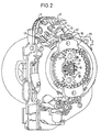
- a spring element 57 is provided which is integral with the Ring gear 23 is formed and from two adjacent arcuate sections (see FIG. 2), each arcuate portion of the spring element 57 a position of Switch rocker 27 is assigned and in this position the latch arm 35 surrounds.
- the latch arm 35 deforms the intermediate web between the two arcuate sections and enters the Area of the left section.
- the rocker switch 27 To pivot the rocker switch 27 are switching cams on the Planet gears 19, 21 are provided.
- the switching cams are through oversized teeth formed on the planet gears 19, 21.
- the Planet gear 19 has a switching cam 25 and the planet gear 21 two Switch cams 59, 61 on (see FIG. 6).
- the second rocker switch 29 is part of a deactivation device, which then blocks the control disc and thereby the locking mechanism, when the webbing has been almost completely pulled off, so that the Belt strap only rolled up and a child seat without play through the Belt strap can be set on the vehicle seat.
- the second rocker switch 29 corresponds in shape to the first rocker switch 27, wherein only the switching arm 37 is designed differently and a facial expression Blocking of the control disc actuated.
- the second rocker switch 29 is diametrically with respect to the sun gear 17 of the first rocker switch 27 arranged opposite each other.
- the switching cam 59 already hits at a short length of pulled webbing on the rocker switch 27 and actuated this.
- the Planet gear 19 moves after actuation of the rocker switch 27 to Continue putting on the webbing.
- the locking mechanism of the belt retractor can be both vehicle-sensitive as well as webbing sensitive.
- the switching cam 25 of the planet gear 19 hits the rocker switch 29 and pivots it back into the first Position.
- the switching cam 61 also strikes the actuating arm 33 and pivots the rocker switch 27 into the first position in which the Switch 31 is in the off position and line 55 interrupts.
- the control unit cannot hold the gas generator in the event of a restraint activate, which is also not necessary, since the Belt seat assigned vehicle seat is not occupied.
- FIG. 7 essentially corresponds that previously shown, but instead of two three planet gears 19, 21, 22 are provided.
- Each planet gear 19, 21, 22 is with a Switch cams 25 ', 59', 61 'provided at a predetermined deducted webbing length one of the two rocker switches 27, 29 actuated.
- the switching cam 59 'on the planet gear 21 serves the purpose Transfer of the rocker switch 27 from the first to the second position.
- the switching cam 61 'on the planet gear 22 pivots the switching rocker 27 back to the first position. He also operates the rocker switch 29 to move it from the first to the second position. Out this second position, the rocker switch 29 by hitting the Switch cam 25 'on the planet gear 19 back to the first position transferred.
Landscapes
- Engineering & Computer Science (AREA)
- Mechanical Engineering (AREA)
- Automotive Seat Belt Assembly (AREA)
Claims (12)
- Enrouleur de ceinture pour une ceinture de sécurité de véhicule, comportant une bobine de ceinture montée rotative dans un boítier, une sangle de ceinture enroulée sur la bobine de ceinture, un mécanisme de blocage (11) pour bloquer la rotation de la bobine de ceinture, un engrenage à roue dentée planétaire avec une roue solaire (17) raccordée de manière solidaire en rotation à la bobine de ceinture, une couronne de train planétaire (23) solidaire du boítier et au moins une roue planétaire (19, 21, 22) qui présente une denture extérieure, ainsi qu'une unité de commutation électrique pour déterminer l'état d'application en raison de la longueur de la sangle de ceinture retirée, l'unité de commutation étant couplée électriquement avec une unité de commande pour activer un générateur de gaz et comprenant un levier de commutation actionnable par le mouvement de la roue planétaire (19, 21, 22), caractérisé en ce que le levier de commutation est réalisé en tant que bascule de commutation (27) pivotable entre une première position et une deuxième position, et en ce que la roue planétaire (19, 21, 22) présente au moins une came de commutation (59, 59', 61, 61') qui, en cas de longueur prédéterminée de sangle retirée, engage directement la bascule de commutation (28) et fait passer la bascule de commutation depuis la première position jusque dans la deuxième position, et en ce que l'unité de commutation présente un interrupteur électrique agencé de manière adjacente à la bascule de commutation (27), lequel est électriquement couplé à l'unité de commande, et en ce que l'interrupteur (31) comprend un poussoir de commutation (41) engageant la bascule de commutation (27), lequel est actionné lorsque la bascule de commutation (27) pivote.
- Enrouleur de ceinture selon la revendication 1, caractérisé en ce que la bascule de commutation (27) présente deux bras d'actionnement (33), en ce que lorsqu'on retire la sangle de ceinture en poussant une came de commutation (59, 59', 61, 61') contre un bras d'actionnement (33), elle est pivotée depuis la première position jusque dans la deuxième position et lorsqu'on enroule la sangle de ceinture en poussant une autre came de commutation (59, 59', 61, 61') contre l'autre bras d'actionnement, elle revient en pivotant jusque dans la première position.
- Enrouleur de ceinture selon la revendication 1 ou 2, caractérisé en ce qu'il est prévu plusieurs cames de commutation (59, 59', 61, 71') sur différentes roues planétaires (19, 21, 22).
- Enrouleur de ceinture selon l'une des revendications précédentes, caractérisé en ce que la bascule de commutation (27) présente un bras de commutation (37) s'étendant radialement vers l'extérieur avec une surface de commande (39) tournée vers l'extérieur et en ce que le poussoir de commutation (41) repose sur la surface de commande (39) et est actionné par pivotement de la bascule de commutation (27).
- Enrouleur de ceinture selon l'une des revendications précédentes, caractérisé en ce que l'interrupteur (31) est réalisé sous forme d'unité préassemblée et présente un boítier d'interrupteur (43) qui est fixé sur l'enrouleur de ceinture par une liaison par encliquetage (45).
- Enrouleur de ceinture selon l'une des revendications précédentes, caractérisé par un élément ressort (57) stationnaire qui engage la bascule de commutation (27) et qui tend à retenir celle-ci dans la position respective qu'elle a adoptée.
- Enrouleur de ceinture selon la revendication 6, caractérisé en ce que l'élément ressort (57) est un prolongement moulé sur la couronne de train planétaire (23) et en ce que la bascule de commutation (27) présente un bras d'enclenchement (35) qui est sais par l'élément ressort (57) dans les deux positions.
- Enrouleur de ceinture selon l'une des revendications précédentes, caractérisé en ce que la came de commutation (59, 59', 61, 61') est un prolongement axial moulé sur une dent de la roue planétaire (19, 21).
- Enrouleur de ceinture selon l'une des revendications précédentes, caractérisé par un mécanisme de déclenchement comportant un disque de commande qui peut tourner de manière limitée par rapport à la bobine de ceinture, par la rotation relative duquel par rapport à la bobine de ceinture le mécanisme de blocage (11) peut être activé, ainsi que par un dispositif de désactivation comportant une deuxième bascule de commutation (29) qui, dans une première position de commutation, bloque le disque de commande et par conséquent le mécanisme de blocage.
- Enrouleur de ceinture selon la revendication 9, caractérisé en ce que la configuration de la deuxième bascule de commutation (29) correspond sensiblement à celle de la première bascule de commutation (27) et peut être déplacée par au moins une came de commutation (25, 25', 59, 59', 61, 61') sur une roue planétaire (19, 21, 22) depuis la première position de commutation jusque dans la deuxième position de commutation et en retour.
- Enrouleur de ceinture selon la revendication 10, caractérisé en ce que la même came de commutation (59, 61') peut actionner tant la première que la deuxième bascule de commutation (27, 29).
- Enrouleur de ceinture selon l'une des revendications 9 à 11, caractérisé en ce que la deuxième bascule de commutation (29) est agencée diamétralement opposée à la première bascule de commutation (27), par rapport à la roue solaire (17).
Applications Claiming Priority (2)
| Application Number | Priority Date | Filing Date | Title |
|---|---|---|---|
| DE29702610U | 1997-02-14 | ||
| DE29702610U DE29702610U1 (de) | 1997-02-14 | 1997-02-14 | Gurtaufroller für einen Fahrzeugsicherheitsgurt |
Publications (3)
| Publication Number | Publication Date |
|---|---|
| EP0858936A2 EP0858936A2 (fr) | 1998-08-19 |
| EP0858936A3 EP0858936A3 (fr) | 2000-01-12 |
| EP0858936B1 true EP0858936B1 (fr) | 2003-08-27 |
Family
ID=8035969
Family Applications (1)
| Application Number | Title | Priority Date | Filing Date |
|---|---|---|---|
| EP98101373A Expired - Lifetime EP0858936B1 (fr) | 1997-02-14 | 1998-01-27 | Enrouleur pour une ceinture de sécurité de véhicule |
Country Status (6)
| Country | Link |
|---|---|
| US (1) | US5931401A (fr) |
| EP (1) | EP0858936B1 (fr) |
| JP (1) | JPH10236278A (fr) |
| KR (1) | KR19980071273A (fr) |
| DE (3) | DE29702610U1 (fr) |
| ES (1) | ES2205286T3 (fr) |
Families Citing this family (9)
| Publication number | Priority date | Publication date | Assignee | Title |
|---|---|---|---|---|
| US6702056B2 (en) * | 1997-08-06 | 2004-03-09 | Takata Corporation | Seatbelt retractor |
| JP4467688B2 (ja) * | 1999-01-19 | 2010-05-26 | タカタ株式会社 | シートベルト巻取装置 |
| DE19940034C2 (de) * | 1999-08-24 | 2001-08-30 | Hs Tech & Design | Gurtaufroller |
| DE19957802A1 (de) * | 1999-12-01 | 2001-06-07 | Trw Repa Gmbh | Gurtaufrollersystem |
| DE20019468U1 (de) * | 2000-11-16 | 2001-03-29 | Trw Repa Gmbh | Gurtaufroller für einen Fahrzeug-Sicherheitsgurt |
| DE60106916T2 (de) | 2001-09-27 | 2005-12-08 | Key Safety Systems, Inc., Sterling Heights | Gurtaufroller mit automatischem Blockiermechanismus |
| DE10248262B3 (de) * | 2002-10-16 | 2004-03-25 | Autoliv Development Ab | Insassen-Sicherheitssystem mit elektrischer Retractor-Umschaltung |
| US6817629B2 (en) * | 2002-10-29 | 2004-11-16 | Trw Vehicle Safety Systems Inc. | Four-point seat belt system having occupant lockable retractors |
| US10737602B2 (en) * | 2018-11-07 | 2020-08-11 | Ford Global Technologies, Llc | Deployable armrest |
Family Cites Families (9)
| Publication number | Priority date | Publication date | Assignee | Title |
|---|---|---|---|---|
| US3880379A (en) * | 1971-12-21 | 1975-04-29 | Allied Chem | Retractor with switch |
| JPS63145747U (fr) * | 1987-03-18 | 1988-09-26 | ||
| DE9318286U1 (de) * | 1993-11-30 | 1994-02-03 | Trw Repa Gmbh | Gurtaufroller für Fahrzeugsicherheitsgurte |
| JP3494769B2 (ja) * | 1994-12-20 | 2004-02-09 | 株式会社東海理化電機製作所 | 助手席又は後席用エアバッグ装置 |
| US5501293A (en) * | 1995-01-23 | 1996-03-26 | Autoliv Development Ab | Safety belt retractor |
| DE29520425U1 (de) * | 1995-12-22 | 1996-04-25 | Trw Repa Gmbh | Gurtaufroller für Fahrzeugsicherheitsgurte |
| DE29605803U1 (de) * | 1996-03-28 | 1996-07-25 | Trw Repa Gmbh | Gurtaufroller für ein Fahrzeug-Sicherheitsgurtsystem |
| DE29608209U1 (de) * | 1996-05-06 | 1996-09-05 | Trw Repa Gmbh | Gurtaufroller für Fahrzeugsicherheitsgurte |
| US5938138A (en) * | 1996-06-06 | 1999-08-17 | Kabushiki Kaisha Tokai-Rika-Denki-Seisakusho | Webbing retractor |
-
1997
- 1997-02-14 DE DE29702610U patent/DE29702610U1/de not_active Expired - Lifetime
-
1998
- 1998-01-09 DE DE29800250U patent/DE29800250U1/de not_active Expired - Lifetime
- 1998-01-27 EP EP98101373A patent/EP0858936B1/fr not_active Expired - Lifetime
- 1998-01-27 ES ES98101373T patent/ES2205286T3/es not_active Expired - Lifetime
- 1998-01-27 DE DE59809368T patent/DE59809368D1/de not_active Expired - Fee Related
- 1998-02-09 US US09/020,739 patent/US5931401A/en not_active Expired - Fee Related
- 1998-02-12 KR KR1019980004091A patent/KR19980071273A/ko not_active Application Discontinuation
- 1998-02-13 JP JP10031505A patent/JPH10236278A/ja active Pending
Also Published As
| Publication number | Publication date |
|---|---|
| JPH10236278A (ja) | 1998-09-08 |
| DE29800250U1 (de) | 1998-06-10 |
| US5931401A (en) | 1999-08-03 |
| DE29702610U1 (de) | 1997-06-12 |
| KR19980071273A (ko) | 1998-10-26 |
| ES2205286T3 (es) | 2004-05-01 |
| EP0858936A3 (fr) | 2000-01-12 |
| DE59809368D1 (de) | 2003-10-02 |
| EP0858936A2 (fr) | 1998-08-19 |
Similar Documents
| Publication | Publication Date | Title |
|---|---|---|
| DE19609524C2 (de) | Gurtaufroller-Gurtstrammer-Kombination mit Kraftbegrenzer | |
| EP1487679B1 (fr) | Pre-tentionneur performant | |
| EP2084042B1 (fr) | Enrouleur de ceinture de securite avec desactivation de son systeme de commande reagissant à la sangle de ceinture et de son systeme de commande reagissant au vehicule | |
| EP0806326B1 (fr) | Rétracteur pour ceintures de sécurité de véhicule automobile | |
| EP1963146B1 (fr) | Enrouleur de ceinture de securite comportant un limitateur de force commande en fonction de l'extraction de la ceinture | |
| DE19907962B4 (de) | Sicherheitsgurtvorrichtung mit Gurtstraffer | |
| EP0581288A1 (fr) | Tendeur pour systèmes de ceintures de sécurité dans des véhicules automobiles | |
| EP0858936B1 (fr) | Enrouleur pour une ceinture de sécurité de véhicule | |
| EP0865975B1 (fr) | Rétracteur pour ceinture de sécurité de véhicule automobile | |
| DE10360032B4 (de) | Gurtaufroller für einen Fahrzeug-Sicherheitsgurt | |
| EP0655372B1 (fr) | Rétracteur de sangle pour ceintures de sécurité de véhicule | |
| DE29704974U9 (de) | Gurtaufroller für einen Fahrzeug-Sicherheitsgurt | |
| EP2456641B1 (fr) | Enrouleur pour une ceinture de sécurité de véhicule | |
| DE3008299A1 (de) | Aufrollautomat fuer einen sicherheitsgurt | |
| EP0535551B1 (fr) | Enrouleur à blocage automatique pour ceinture de sécurité avec communication de rétracteur | |
| DE4417064A1 (de) | Rückhaltesystem mit Airbagsteuerung | |
| DE60106916T2 (de) | Gurtaufroller mit automatischem Blockiermechanismus | |
| DE19541430C2 (de) | Elektrisch gesteuerter Sicherheitsgurtaufroller | |
| EP0625449B2 (fr) | Rétracteur pour ceinture de sécurité | |
| DE602004003663T2 (de) | Sicherheitsgurtaufroller | |
| DE102006023258B3 (de) | Sicherheitsgurtaufroller mit bei Beginn der Kraftbegrenzung aufschaltbarer zweiter Kraftbegrenzungsstufe | |
| WO2003020557A1 (fr) | Enrouleur de ceinture de securite equipe d'un limiteur d'effort a enclenchement mecanique | |
| EP1501708B1 (fr) | Enrouleur de ceinture de securite presentant un capteur de vehicule qui peut etre deconnecte | |
| EP0543044B1 (fr) | Rétracteur de sangle avec soulagement de traction pour systèmes de retenue par ceinture de sécurité pour véhicules | |
| DE3509254A1 (de) | Sicherheitsgurtaufroller |
Legal Events
| Date | Code | Title | Description |
|---|---|---|---|
| PUAI | Public reference made under article 153(3) epc to a published international application that has entered the european phase |
Free format text: ORIGINAL CODE: 0009012 |
|
| AK | Designated contracting states |
Kind code of ref document: A2 Designated state(s): DE ES FR GB IT |
|
| AX | Request for extension of the european patent |
Free format text: AL;LT;LV;MK;RO;SI |
|
| PUAL | Search report despatched |
Free format text: ORIGINAL CODE: 0009013 |
|
| AK | Designated contracting states |
Kind code of ref document: A3 Designated state(s): AT BE CH DE DK ES FI FR GB GR IE IT LI LU MC NL PT SE |
|
| AX | Request for extension of the european patent |
Free format text: AL;LT;LV;MK;RO;SI |
|
| RIC1 | Information provided on ipc code assigned before grant |
Free format text: 7B 60R 22/48 A, 7B 60R 22/34 B, 7B 60R 22/353 B, 7B 60R 22/415 B |
|
| 17P | Request for examination filed |
Effective date: 20000418 |
|
| AKX | Designation fees paid |
Free format text: DE ES FR GB IT |
|
| 17Q | First examination report despatched |
Effective date: 20020206 |
|
| GRAH | Despatch of communication of intention to grant a patent |
Free format text: ORIGINAL CODE: EPIDOS IGRA |
|
| GRAS | Grant fee paid |
Free format text: ORIGINAL CODE: EPIDOSNIGR3 |
|
| GRAA | (expected) grant |
Free format text: ORIGINAL CODE: 0009210 |
|
| AK | Designated contracting states |
Designated state(s): DE ES FR GB IT |
|
| REG | Reference to a national code |
Ref country code: GB Ref legal event code: FG4D Free format text: NOT ENGLISH |
|
| REF | Corresponds to: |
Ref document number: 59809368 Country of ref document: DE Date of ref document: 20031002 Kind code of ref document: P |
|
| GBT | Gb: translation of ep patent filed (gb section 77(6)(a)/1977) |
Effective date: 20031007 |
|
| PG25 | Lapsed in a contracting state [announced via postgrant information from national office to epo] |
Ref country code: GB Free format text: LAPSE BECAUSE OF NON-PAYMENT OF DUE FEES Effective date: 20040127 |
|
| REG | Reference to a national code |
Ref country code: ES Ref legal event code: FG2A Ref document number: 2205286 Country of ref document: ES Kind code of ref document: T3 |
|
| ET | Fr: translation filed | ||
| PLBE | No opposition filed within time limit |
Free format text: ORIGINAL CODE: 0009261 |
|
| STAA | Information on the status of an ep patent application or granted ep patent |
Free format text: STATUS: NO OPPOSITION FILED WITHIN TIME LIMIT |
|
| 26N | No opposition filed |
Effective date: 20040528 |
|
| GBPC | Gb: european patent ceased through non-payment of renewal fee |
Effective date: 20040127 |
|
| PGFP | Annual fee paid to national office [announced via postgrant information from national office to epo] |
Ref country code: ES Payment date: 20050120 Year of fee payment: 8 |
|
| PG25 | Lapsed in a contracting state [announced via postgrant information from national office to epo] |
Ref country code: ES Free format text: LAPSE BECAUSE OF NON-PAYMENT OF DUE FEES Effective date: 20060128 |
|
| REG | Reference to a national code |
Ref country code: ES Ref legal event code: FD2A Effective date: 20060128 |
|
| PGFP | Annual fee paid to national office [announced via postgrant information from national office to epo] |
Ref country code: IT Payment date: 20070529 Year of fee payment: 10 |
|
| REG | Reference to a national code |
Ref country code: FR Ref legal event code: ST Effective date: 20080229 |
|
| PGFP | Annual fee paid to national office [announced via postgrant information from national office to epo] |
Ref country code: DE Payment date: 20080131 Year of fee payment: 11 |
|
| PG25 | Lapsed in a contracting state [announced via postgrant information from national office to epo] |
Ref country code: FR Free format text: LAPSE BECAUSE OF NON-PAYMENT OF DUE FEES Effective date: 20040131 |
|
| PG25 | Lapsed in a contracting state [announced via postgrant information from national office to epo] |
Ref country code: IT Free format text: LAPSE BECAUSE OF NON-PAYMENT OF DUE FEES Effective date: 20080127 |
|
| PG25 | Lapsed in a contracting state [announced via postgrant information from national office to epo] |
Ref country code: DE Free format text: LAPSE BECAUSE OF NON-PAYMENT OF DUE FEES Effective date: 20090801 |