EP0806322A2 - Pare-chocs - Google Patents
Pare-chocs Download PDFInfo
- Publication number
- EP0806322A2 EP0806322A2 EP97107162A EP97107162A EP0806322A2 EP 0806322 A2 EP0806322 A2 EP 0806322A2 EP 97107162 A EP97107162 A EP 97107162A EP 97107162 A EP97107162 A EP 97107162A EP 0806322 A2 EP0806322 A2 EP 0806322A2
- Authority
- EP
- European Patent Office
- Prior art keywords
- sleeve
- carrier
- bumper according
- adjusting
- bumper
- Prior art date
- Legal status (The legal status is an assumption and is not a legal conclusion. Google has not performed a legal analysis and makes no representation as to the accuracy of the status listed.)
- Granted
Links
Images
Classifications
-
- B—PERFORMING OPERATIONS; TRANSPORTING
- B60—VEHICLES IN GENERAL
- B60R—VEHICLES, VEHICLE FITTINGS, OR VEHICLE PARTS, NOT OTHERWISE PROVIDED FOR
- B60R19/00—Wheel guards; Radiator guards, e.g. grilles; Obstruction removers; Fittings damping bouncing force in collisions
- B60R19/02—Bumpers, i.e. impact receiving or absorbing members for protecting vehicles or fending off blows from other vehicles or objects
- B60R19/24—Arrangements for mounting bumpers on vehicles
- B60R2019/242—Arrangements for mounting bumpers on vehicles on two vertical sleeves, e.g. on energy absorber ends
-
- B—PERFORMING OPERATIONS; TRANSPORTING
- B60—VEHICLES IN GENERAL
- B60R—VEHICLES, VEHICLE FITTINGS, OR VEHICLE PARTS, NOT OTHERWISE PROVIDED FOR
- B60R19/00—Wheel guards; Radiator guards, e.g. grilles; Obstruction removers; Fittings damping bouncing force in collisions
- B60R19/02—Bumpers, i.e. impact receiving or absorbing members for protecting vehicles or fending off blows from other vehicles or objects
- B60R19/24—Arrangements for mounting bumpers on vehicles
- B60R2019/245—Arrangements for mounting bumpers on vehicles with adjusting means to compensate manufacturing tolerances, e.g. between bumper and energy absorbers
Definitions
- the present invention relates to a bumper according to the preamble of claim 1.
- Adjustment devices are used with which a three-axis adjustment of the bumper in the longitudinal, transverse and vertical directions is possible.
- the known adjusting devices do not offer the possibility of rotating the bumper about its transverse axis without generating transverse forces acting on the fastening elements. Rather, there is a one-sided load on the adjusting device, which is not desirable and impairs the full functionality of the bumper.
- the present invention is therefore based on the object to design a bumper of the generic type so that it can be changed in all axes without loading the fasteners.
- a pivoting of the bumper about the transverse axis can now also take place without transverse forces acting on the load-bearing parts.
- each steep ring has a circumferential collar which rests on the end face of the sleeve, this collar having a dome-like curvature all around on the side facing the sleeve.
- the end face of the sleeve is expediently adapted to this curvature.
- threaded bushes are screwed into the adjusting rings, which have threads that run in opposite directions to the other threaded bushings and that can be rotated by means of a common screw bolt. In the end position of the threaded bushings, they press against the entire surface of the inside of the legs of the U-shaped carrier.
- the carrier can be fixed in any position so that the gap widths are the same everywhere.
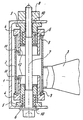
- the single figure shows a part of the bumper according to the invention in cross section.
- a part of a bumper for a motor vehicle which essentially consists of a carrier 1, a spar 3 firmly connected to supporting parts of the motor vehicle and a sleeve 2 which is fastened to the spar 3, for example by welding.
- an adjusting ring 4 is arranged such that it cannot rotate, for which purpose the sleeve 2 has inwardly directed tongues 11 which protrude into openings 12 of the adjusting rings 4.
- the openings 12 are kept so large that a certain free movement of the adjusting rings 4 in the axial and in the tilting direction to the sleeve 2 is possible.
- the outer diameter of the adjusting ring 4 is correspondingly smaller than the inside diameter of the sleeve 2.
- Each of the two adjusting rings 4 is provided with an internal thread into which a threaded bush 5 is screwed.
- the threads of the opposing adjusting rings 4 or the associated threaded bushings 5 are designed in opposite directions.
- a driver ring 6 is fixed in each case in the threaded bushings 5, which is relative to the Bolts have a certain coefficient of friction.
- These drive rings 6 enclose a screw bolt 7 which extends through both threaded bushings 5 and on the one hand rests on the outside of one leg of the U-shaped carrier 1 and on the other hand is screwed into a nut part 8 which is secured against rotation but displaceably on the outside of the other leg is.
- Each leg is provided with a bore 10 through which the screw bolt 7 is guided and the diameter of which is kept so large compared to the diameter of the screw bolt 7 that a relative displacement of the carrier 1 to the threaded bushings 5 is possible both in the longitudinal and in the transverse direction is.
- Each adjusting ring 4 has a collar 9, which is preferably concavely curved on its side facing the sleeve 2 and with this side rests on the associated end face of the sleeve 2 which is adapted to the curvature. With constant complete contact of the collar 9 on the end face of the sleeve 2, the adjusting ring 4 and the carrier 1 connected therewith can be pivoted over a certain angular range relative to the sleeve 2.
- the figure shows the position in which the threaded bushings 5 and thus the steep rings 4 are firmly clamped to the carrier 1.
- the upper threaded bushing 5 is then unscrewed from the adjusting ring 4, the torque to be applied being transmitted through the driving ring 6, which rests frictionally on the screw bolt 7.
- the construction according to the invention thus also allows cross-sectional tolerances of the beam 1 to be compensated for in all directions in addition to the beam setting.
Landscapes
- Engineering & Computer Science (AREA)
- Mechanical Engineering (AREA)
- Connection Of Plates (AREA)
- Clamps And Clips (AREA)
- Fittings On The Vehicle Exterior For Carrying Loads, And Devices For Holding Or Mounting Articles (AREA)
- Pivots And Pivotal Connections (AREA)
- Crystals, And After-Treatments Of Crystals (AREA)
Applications Claiming Priority (2)
| Application Number | Priority Date | Filing Date | Title |
|---|---|---|---|
| DE29608248U DE29608248U1 (de) | 1996-05-07 | 1996-05-07 | Stoßfänger |
| DE29608248U | 1996-05-07 |
Publications (3)
| Publication Number | Publication Date |
|---|---|
| EP0806322A2 true EP0806322A2 (fr) | 1997-11-12 |
| EP0806322A3 EP0806322A3 (fr) | 2000-11-15 |
| EP0806322B1 EP0806322B1 (fr) | 2004-02-25 |
Family
ID=8023649
Family Applications (1)
| Application Number | Title | Priority Date | Filing Date |
|---|---|---|---|
| EP97107162A Expired - Lifetime EP0806322B1 (fr) | 1996-05-07 | 1997-04-30 | Pare-chocs |
Country Status (4)
| Country | Link |
|---|---|
| EP (1) | EP0806322B1 (fr) |
| DE (2) | DE29608248U1 (fr) |
| ES (1) | ES2212011T3 (fr) |
| FR (1) | FR2748434A1 (fr) |
Cited By (2)
| Publication number | Priority date | Publication date | Assignee | Title |
|---|---|---|---|---|
| EP0958967A3 (fr) * | 1998-05-22 | 2002-01-02 | Euromotive Gesellschaft m.b.H. | Dispositif de pose d'un premier composant sur un deuxième composant, d'une poutre de pare-chocs sur un chassis de véhicule en particulier |
| DE102007049138A1 (de) | 2007-10-12 | 2009-04-16 | Audi Ag | Fixiervorrichtung und Verfahren zum Einstellen einer Position wenigstens eines ersten Kraftfahrzeugbauteils bezüglich wenigstens eines zweiten Kraftfahrzeugbauteils |
Families Citing this family (4)
| Publication number | Priority date | Publication date | Assignee | Title |
|---|---|---|---|---|
| DE19634558B4 (de) * | 1996-08-27 | 2010-03-25 | Ise Automotive Gmbh | Vorrichtung aus zwei zueinander verschiebbaren Körpern, Verstellwerkzeug und Verfahren zur Herstellung einer Paarung aus einer solchen Vorrichtung und einem solchen Verstellwerkzeug |
| DE19937941B4 (de) * | 1999-08-11 | 2005-04-21 | Daimlerchrysler Ag | Vorrichtung zur Festlegung einer formintegrierten Stoßfängereinheit |
| DE20022105U1 (de) * | 2000-12-30 | 2002-02-14 | REHAU AG + Co., 95111 Rehau | Abstandhalter |
| DE102006039685B4 (de) * | 2006-08-24 | 2010-01-07 | Audi Ag | Vorrichtung zur Anbringung eines Stoßfängers an einer Karosserie |
Family Cites Families (4)
| Publication number | Priority date | Publication date | Assignee | Title |
|---|---|---|---|---|
| DE2903542A1 (de) * | 1979-01-31 | 1980-08-14 | Daimler Benz Ag | Stossfaengeranordnung fuer einen kraftwagen |
| GB2154953B (en) * | 1984-03-02 | 1987-05-20 | Ford Motor Co | Height adjustable vehicle bumper assembly |
| DE3504060C1 (de) * | 1985-02-07 | 1986-07-10 | Bayerische Motoren Werke AG, 8000 München | Stossfaenger fuer Kraftfahrzeuge |
| DE4333695C1 (de) * | 1993-02-26 | 1994-03-31 | Audi Ag | Vorrichtung zum Einstellen eines ersten Bauteils relativ zu einem zweiten Bauteil |
-
1996
- 1996-05-07 DE DE29608248U patent/DE29608248U1/de not_active Expired - Lifetime
- 1996-10-29 FR FR9613469A patent/FR2748434A1/fr active Pending
-
1997
- 1997-04-30 DE DE59711324T patent/DE59711324D1/de not_active Expired - Lifetime
- 1997-04-30 ES ES97107162T patent/ES2212011T3/es not_active Expired - Lifetime
- 1997-04-30 EP EP97107162A patent/EP0806322B1/fr not_active Expired - Lifetime
Cited By (2)
| Publication number | Priority date | Publication date | Assignee | Title |
|---|---|---|---|---|
| EP0958967A3 (fr) * | 1998-05-22 | 2002-01-02 | Euromotive Gesellschaft m.b.H. | Dispositif de pose d'un premier composant sur un deuxième composant, d'une poutre de pare-chocs sur un chassis de véhicule en particulier |
| DE102007049138A1 (de) | 2007-10-12 | 2009-04-16 | Audi Ag | Fixiervorrichtung und Verfahren zum Einstellen einer Position wenigstens eines ersten Kraftfahrzeugbauteils bezüglich wenigstens eines zweiten Kraftfahrzeugbauteils |
Also Published As
| Publication number | Publication date |
|---|---|
| FR2748434A1 (fr) | 1997-11-14 |
| EP0806322B1 (fr) | 2004-02-25 |
| EP0806322A3 (fr) | 2000-11-15 |
| DE59711324D1 (de) | 2004-04-01 |
| ES2212011T3 (es) | 2004-07-16 |
| DE29608248U1 (de) | 1996-08-01 |
Similar Documents
| Publication | Publication Date | Title |
|---|---|---|
| EP0543046B1 (fr) | Ensemble de vis | |
| DE69802448T2 (de) | Riemenspanner | |
| EP2217469A1 (fr) | Élément de positionnement | |
| DE69006990T2 (de) | Träger für eine Lenksäule. | |
| DE69406361T2 (de) | Abstützvorrichtung für eine Aufhängung | |
| EP4117979B1 (fr) | Colonne de direction pour un véhicule automobile | |
| EP1217222B1 (fr) | Elément de compensation de déviations de tolérance | |
| DE3928876C2 (de) | Einrichtung zum Justieren eines Stoßfängers an einem Kraftfahrzeug | |
| EP0806322A2 (fr) | Pare-chocs | |
| DE10108901A1 (de) | Einstellbare Lenkspurstange | |
| EP0848168B1 (fr) | Elément de support à réglage axial | |
| DE2834333A1 (de) | Vorrichtung zur aufhaengung von fahrzeugraedern und zur einstellung des sturzwinkels | |
| DE102023002488B4 (de) | Befestigungsvorrichtung zur Befestigung eines Lidarsensors in einem Fahrzeug, Lidarsystem und Fahrzeug | |
| DE202017105765U1 (de) | Befestigungsvorrichtung zur Befestigung von mindestens einem Bauteil | |
| DE202023104401U1 (de) | Lenkervorbau | |
| DE4333695C1 (de) | Vorrichtung zum Einstellen eines ersten Bauteils relativ zu einem zweiten Bauteil | |
| DE102004039253B4 (de) | Haltevorrichtung für einen Bowdenzug sowie Fahrzeugsitz | |
| DE2726740A1 (de) | Verschwenkbare halterung fuer einen tragarm eines rueckspiegels fuer kraftfahrzeuge | |
| DE102011000990B4 (de) | Sattelstütze | |
| EP4411151B1 (fr) | Élément de réglage doté d'un manchon de fixation amortissant et son procédé d'installation et de fabrication | |
| DE102024000853B3 (de) | Radträgeranordnung für ein Fahrzeug und Verfahren zur Einstellung eines Radsturzes eines Fahrzeugs | |
| EP1651835B1 (fr) | Unite de transmission et d'entrainement | |
| DE102019004287A1 (de) | Verankerungsanordnung zum Verankern eines Gurtverankerungselementes für einen Sicherheitsgurt an einem Fahrzeugbauteil | |
| EP3822021B1 (fr) | Appui modulaire | |
| EP3713820A1 (fr) | Système de fixation pour véhicule automobile pour fixer un premier composant de véhicule automobile à un deuxième composant de véhicule automobile |
Legal Events
| Date | Code | Title | Description |
|---|---|---|---|
| PUAI | Public reference made under article 153(3) epc to a published international application that has entered the european phase |
Free format text: ORIGINAL CODE: 0009012 |
|
| AK | Designated contracting states |
Kind code of ref document: A2 Designated state(s): DE ES FR GB IT |
|
| PUAL | Search report despatched |
Free format text: ORIGINAL CODE: 0009013 |
|
| AK | Designated contracting states |
Kind code of ref document: A3 Designated state(s): DE ES FR GB IT |
|
| RIC1 | Information provided on ipc code assigned before grant |
Free format text: 7B 60R 19/38 A, 7B 60R 19/24 B |
|
| 17P | Request for examination filed |
Effective date: 20010511 |
|
| 17Q | First examination report despatched |
Effective date: 20030115 |
|
| GRAP | Despatch of communication of intention to grant a patent |
Free format text: ORIGINAL CODE: EPIDOSNIGR1 |
|
| GRAS | Grant fee paid |
Free format text: ORIGINAL CODE: EPIDOSNIGR3 |
|
| GRAA | (expected) grant |
Free format text: ORIGINAL CODE: 0009210 |
|
| AK | Designated contracting states |
Kind code of ref document: B1 Designated state(s): DE ES FR GB IT |
|
| REG | Reference to a national code |
Ref country code: GB Ref legal event code: FG4D Free format text: NOT ENGLISH |
|
| REF | Corresponds to: |
Ref document number: 59711324 Country of ref document: DE Date of ref document: 20040401 Kind code of ref document: P |
|
| GBT | Gb: translation of ep patent filed (gb section 77(6)(a)/1977) |
Effective date: 20040414 |
|
| REG | Reference to a national code |
Ref country code: ES Ref legal event code: FG2A Ref document number: 2212011 Country of ref document: ES Kind code of ref document: T3 |
|
| ET | Fr: translation filed | ||
| PLBE | No opposition filed within time limit |
Free format text: ORIGINAL CODE: 0009261 |
|
| STAA | Information on the status of an ep patent application or granted ep patent |
Free format text: STATUS: NO OPPOSITION FILED WITHIN TIME LIMIT |
|
| 26N | No opposition filed |
Effective date: 20041126 |
|
| PGFP | Annual fee paid to national office [announced via postgrant information from national office to epo] |
Ref country code: DE Payment date: 20120430 Year of fee payment: 16 |
|
| PGFP | Annual fee paid to national office [announced via postgrant information from national office to epo] |
Ref country code: FR Payment date: 20120510 Year of fee payment: 16 Ref country code: GB Payment date: 20120425 Year of fee payment: 16 |
|
| PGFP | Annual fee paid to national office [announced via postgrant information from national office to epo] |
Ref country code: IT Payment date: 20120421 Year of fee payment: 16 |
|
| PGFP | Annual fee paid to national office [announced via postgrant information from national office to epo] |
Ref country code: ES Payment date: 20120420 Year of fee payment: 16 |
|
| GBPC | Gb: european patent ceased through non-payment of renewal fee |
Effective date: 20130430 |
|
| PG25 | Lapsed in a contracting state [announced via postgrant information from national office to epo] |
Ref country code: DE Free format text: LAPSE BECAUSE OF NON-PAYMENT OF DUE FEES Effective date: 20131101 Ref country code: GB Free format text: LAPSE BECAUSE OF NON-PAYMENT OF DUE FEES Effective date: 20130430 |
|
| REG | Reference to a national code |
Ref country code: FR Ref legal event code: ST Effective date: 20131231 |
|
| REG | Reference to a national code |
Ref country code: DE Ref legal event code: R119 Ref document number: 59711324 Country of ref document: DE Effective date: 20131101 |
|
| PG25 | Lapsed in a contracting state [announced via postgrant information from national office to epo] |
Ref country code: FR Free format text: LAPSE BECAUSE OF NON-PAYMENT OF DUE FEES Effective date: 20130430 Ref country code: IT Free format text: LAPSE BECAUSE OF NON-PAYMENT OF DUE FEES Effective date: 20130430 |
|
| REG | Reference to a national code |
Ref country code: ES Ref legal event code: FD2A Effective date: 20140606 |
|
| PG25 | Lapsed in a contracting state [announced via postgrant information from national office to epo] |
Ref country code: ES Free format text: LAPSE BECAUSE OF NON-PAYMENT OF DUE FEES Effective date: 20130501 |