EP0806322A2 - Bumper - Google Patents
Bumper Download PDFInfo
- Publication number
- EP0806322A2 EP0806322A2 EP97107162A EP97107162A EP0806322A2 EP 0806322 A2 EP0806322 A2 EP 0806322A2 EP 97107162 A EP97107162 A EP 97107162A EP 97107162 A EP97107162 A EP 97107162A EP 0806322 A2 EP0806322 A2 EP 0806322A2
- Authority
- EP
- European Patent Office
- Prior art keywords
- sleeve
- carrier
- bumper according
- adjusting
- bumper
- Prior art date
- Legal status (The legal status is an assumption and is not a legal conclusion. Google has not performed a legal analysis and makes no representation as to the accuracy of the status listed.)
- Granted
Links
Images
Classifications
-
- B—PERFORMING OPERATIONS; TRANSPORTING
- B60—VEHICLES IN GENERAL
- B60R—VEHICLES, VEHICLE FITTINGS, OR VEHICLE PARTS, NOT OTHERWISE PROVIDED FOR
- B60R19/00—Wheel guards; Radiator guards, e.g. grilles; Obstruction removers; Fittings damping bouncing force in collisions
- B60R19/02—Bumpers, i.e. impact receiving or absorbing members for protecting vehicles or fending off blows from other vehicles or objects
- B60R19/24—Arrangements for mounting bumpers on vehicles
- B60R2019/242—Arrangements for mounting bumpers on vehicles on two vertical sleeves, e.g. on energy absorber ends
-
- B—PERFORMING OPERATIONS; TRANSPORTING
- B60—VEHICLES IN GENERAL
- B60R—VEHICLES, VEHICLE FITTINGS, OR VEHICLE PARTS, NOT OTHERWISE PROVIDED FOR
- B60R19/00—Wheel guards; Radiator guards, e.g. grilles; Obstruction removers; Fittings damping bouncing force in collisions
- B60R19/02—Bumpers, i.e. impact receiving or absorbing members for protecting vehicles or fending off blows from other vehicles or objects
- B60R19/24—Arrangements for mounting bumpers on vehicles
- B60R2019/245—Arrangements for mounting bumpers on vehicles with adjusting means to compensate manufacturing tolerances, e.g. between bumper and energy absorbers
Definitions
- the present invention relates to a bumper according to the preamble of claim 1.
- Adjustment devices are used with which a three-axis adjustment of the bumper in the longitudinal, transverse and vertical directions is possible.
- the known adjusting devices do not offer the possibility of rotating the bumper about its transverse axis without generating transverse forces acting on the fastening elements. Rather, there is a one-sided load on the adjusting device, which is not desirable and impairs the full functionality of the bumper.
- the present invention is therefore based on the object to design a bumper of the generic type so that it can be changed in all axes without loading the fasteners.
- a pivoting of the bumper about the transverse axis can now also take place without transverse forces acting on the load-bearing parts.
- each steep ring has a circumferential collar which rests on the end face of the sleeve, this collar having a dome-like curvature all around on the side facing the sleeve.
- the end face of the sleeve is expediently adapted to this curvature.
- threaded bushes are screwed into the adjusting rings, which have threads that run in opposite directions to the other threaded bushings and that can be rotated by means of a common screw bolt. In the end position of the threaded bushings, they press against the entire surface of the inside of the legs of the U-shaped carrier.
- the carrier can be fixed in any position so that the gap widths are the same everywhere.
- the single figure shows a part of the bumper according to the invention in cross section.
- a part of a bumper for a motor vehicle which essentially consists of a carrier 1, a spar 3 firmly connected to supporting parts of the motor vehicle and a sleeve 2 which is fastened to the spar 3, for example by welding.
- an adjusting ring 4 is arranged such that it cannot rotate, for which purpose the sleeve 2 has inwardly directed tongues 11 which protrude into openings 12 of the adjusting rings 4.
- the openings 12 are kept so large that a certain free movement of the adjusting rings 4 in the axial and in the tilting direction to the sleeve 2 is possible.
- the outer diameter of the adjusting ring 4 is correspondingly smaller than the inside diameter of the sleeve 2.
- Each of the two adjusting rings 4 is provided with an internal thread into which a threaded bush 5 is screwed.
- the threads of the opposing adjusting rings 4 or the associated threaded bushings 5 are designed in opposite directions.
- a driver ring 6 is fixed in each case in the threaded bushings 5, which is relative to the Bolts have a certain coefficient of friction.
- These drive rings 6 enclose a screw bolt 7 which extends through both threaded bushings 5 and on the one hand rests on the outside of one leg of the U-shaped carrier 1 and on the other hand is screwed into a nut part 8 which is secured against rotation but displaceably on the outside of the other leg is.
- Each leg is provided with a bore 10 through which the screw bolt 7 is guided and the diameter of which is kept so large compared to the diameter of the screw bolt 7 that a relative displacement of the carrier 1 to the threaded bushings 5 is possible both in the longitudinal and in the transverse direction is.
- Each adjusting ring 4 has a collar 9, which is preferably concavely curved on its side facing the sleeve 2 and with this side rests on the associated end face of the sleeve 2 which is adapted to the curvature. With constant complete contact of the collar 9 on the end face of the sleeve 2, the adjusting ring 4 and the carrier 1 connected therewith can be pivoted over a certain angular range relative to the sleeve 2.
- the figure shows the position in which the threaded bushings 5 and thus the steep rings 4 are firmly clamped to the carrier 1.
- the upper threaded bushing 5 is then unscrewed from the adjusting ring 4, the torque to be applied being transmitted through the driving ring 6, which rests frictionally on the screw bolt 7.
- the construction according to the invention thus also allows cross-sectional tolerances of the beam 1 to be compensated for in all directions in addition to the beam setting.
Landscapes
- Engineering & Computer Science (AREA)
- Mechanical Engineering (AREA)
- Connection Of Plates (AREA)
- Clamps And Clips (AREA)
- Fittings On The Vehicle Exterior For Carrying Loads, And Devices For Holding Or Mounting Articles (AREA)
- Pivots And Pivotal Connections (AREA)
- Crystals, And After-Treatments Of Crystals (AREA)
Abstract
Der Träger (1) eines Stoßfängers für ein Kraftfahrzeug ist mittels Verstelleinrichtungen in allen Achsen lageveränderbar an Holmen (3) des Kraftfahrzeuges angeschlossen. An jedem Holm (3) ist quer zur Längsachse des Trägers (1) eine Hülse (2) befestigt, in der in den sich gegenüberliegenden Endbereichen verdrehsicher und um einen Winkelbereich kippbar gehaltene, mit dem Träger (1) verspannte Stellringe (4) angeordnet sind.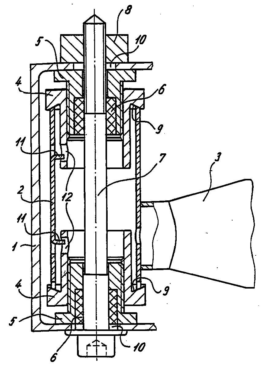
Description
Die vorliegende Erfindung betrifft einen Stoßfänger gemäß dem Oberbegriff des Anspruches 1.The present invention relates to a bumper according to the preamble of
Fertigungsbedingt ergeben sich bei der Montage von Stoßfängern Probleme beim Ausgleich von Toleranzen. Durch einen solchen Ausgleich soll der optische Gesamteindruck optimiert werden. Das heißt, die Spaltbreiten zwischen der Karosserie und dem verkleideten Stoßfänger sollen über die gesamte Spaltlänge gleich groß gehalten werden.Due to the manufacturing process, there are problems in compensating tolerances when installing bumpers. The overall visual impression is to be optimized by such a compensation. This means that the gap widths between the body and the clad bumper should be kept the same across the entire gap length.
Es kommen Verstelleinrichtungen zum Einsatz, mit denen eine Dreiachsenverstellung des Stoßfänger in Längs-, Quer- und Vertikalrichtung möglich ist.Adjustment devices are used with which a three-axis adjustment of the bumper in the longitudinal, transverse and vertical directions is possible.
Die bekannten Verstelleinrichtungen bieten jedoch keine Möglichkeit, den Stoßfänger um seine Querachse zu drehen, ohne auf die Befestigungselemente wirkende Querkräfte zu erzeugen. Vielmehr tritt hierbei eine einseitige Belastung der Verstelleinrichtung auf, die nicht wünschenswert ist und die volle Funktionsfähigkeit des Stoßfängers beeinträchtigt.However, the known adjusting devices do not offer the possibility of rotating the bumper about its transverse axis without generating transverse forces acting on the fastening elements. Rather, there is a one-sided load on the adjusting device, which is not desirable and impairs the full functionality of the bumper.
Der vorliegenden Erfindung liegt daher die Aufgabe zugrunde, einen Stoßfänger der gattungsgemäßen Art so zu gestalten, daß er in allen Achsen ohne Belastung der Befestigungselemente lageveränderbar ist.The present invention is therefore based on the object to design a bumper of the generic type so that it can be changed in all axes without loading the fasteners.
Diese Aufgabe wird durch einen Stoßfänger gelöst, der die Merkmale des Anspruches 1 aufweist.This object is achieved by a bumper which has the features of
Eine Verschwenkung des Stoßfängers um die Querachse kann nunmehr auch erfolgen, ohne daß auf die lastaufnehmenden Teile Querkräfte einwirken.A pivoting of the bumper about the transverse axis can now also take place without transverse forces acting on the load-bearing parts.
Dies wird dadurch erreicht, daß praktisch in jeder Stellung des Trägers die Stellringe auf der gesamten zugeordneten Stirnfläche der Hülse aufliegen.This is achieved in that the adjusting rings rest on the entire associated end face of the sleeve practically in any position of the carrier.
Während die Hülse starr mit dem Holm verbunden ist und insoweit bei einer Verstellung des Trägers auch in dieser Position verbleibt, verschwenken die Stellringe und damit der angeschlossene Träger um den gewünschten Winkelbetrag, wobei der Träger mit den Stellringen ohne Verkanten voll verspannt werden kann.While the sleeve is rigidly connected to the spar and so far remains in this position when the carrier is adjusted, the adjusting rings and thus the connected carrier pivot by the desired angular amount, the carrier being able to be fully braced with the adjusting rings without tilting.
Nach einer vorteilhaften Ausgestaltung der Erfindung ist vorgesehen, daß jeder Steilring einen umlaufenden Kragen aufweist, der auf der Stirnfläche der Hülse aufliegt wobei dieser Kragen auf der der Hülse zugewandten Seite umlaufend eine kalottenartige Wölbung aufweist. Zweckmäßigerweise ist die Stirnseite der Hülse dieser Wölbung angepaßt.According to an advantageous embodiment of the invention it is provided that each steep ring has a circumferential collar which rests on the end face of the sleeve, this collar having a dome-like curvature all around on the side facing the sleeve. The end face of the sleeve is expediently adapted to this curvature.
Zum Verspannen der Stellringe bzw. des Trägers und dessen Toleranzausgleich sind in die Stellringe Gewindebuchsen eingeschraubt, die ein zur anderen Gewindebuchse gegenläufiges Gewinde aufweisen und die über einen gemeinsamen Schraubbolzen drehbar sind. In Endstellung der Gewindebuchsen liegen diese vollflächig an den Innenseiten der Schenkel des U-förmigen Trägers pressend an.To clamp the adjusting rings or the carrier and to compensate for their tolerances, threaded bushes are screwed into the adjusting rings, which have threads that run in opposite directions to the other threaded bushings and that can be rotated by means of a common screw bolt. In the end position of the threaded bushings, they press against the entire surface of the inside of the legs of the U-shaped carrier.
Hierdurch kann der Träger in jeder Position so festgesetzt werden, daß die Spaltbreiten überall gleich groß sind.As a result, the carrier can be fixed in any position so that the gap widths are the same everywhere.
Zudem wird erreicht, daß bei einem Anziehen des Schraubbolzens mit einem vorgegebenen Drehmoment die Gewindebuchsen stets vollflächig verspannt werden, so daß Setzeffekte durch lokale hohe Flächenpressungen vermieden werden.In addition, it is achieved that when the screw bolt is tightened with a predetermined torque, the threaded bushings are always braced over the entire surface, so that setting effects due to local high surface pressures are avoided.
Weitere vorteilhafte Ausgestaltungen der Erfindung sind in den Unteransprüchen gekennzeichnet.Further advantageous embodiments of the invention are characterized in the subclaims.
Ein Ausführungsbeispiel der Erfindung wird nachfolgend anhand der beigefügten Zeichnung beschrieben.An embodiment of the invention is described below with reference to the accompanying drawings.
Die einzige Figur zeigt einen Teil des erfindungsgemäßen Stoßfängers im Querschnitt.The single figure shows a part of the bumper according to the invention in cross section.
In der Figur ist ein Teil eines Stoßfängers für ein Kraftfahrzeug gezeigt, das im wesentlichen aus einem Träger 1, einem fest mit tragenden Teilen des Kraftfahrzeuges verbundenen Holm 3 sowie einer Hülse 2 besteht, die an dem Holm 3, beispielsweise durch Verschweißen befestigt ist.In the figure, a part of a bumper for a motor vehicle is shown, which essentially consists of a
In den beiden Endbereichen der Hülse 2 sind jeweils ein Stellring 4 verdrehsicher angeordnet, wozu die Hülse 2 nach innen gerichtete Zungen 11 aufweist, die in Öffnungen 12 der Stellringe 4 hineinragen.In the two end regions of the sleeve 2, an adjusting ring 4 is arranged such that it cannot rotate, for which purpose the sleeve 2 has inwardly directed
Die Öffnungen 12 sind dabei so groß gehalten, daß eine gewisse freie Bewegung der Stellringe 4 in axialer sowie in Kipprichtung zur Hülse 2 möglich ist.The
Insbesondere um ein Verschwenken des Stellringes innerhalb eines Winkelbereichs zu ermöglichen, ist der Außendurchmesser des Stellringes 4 entsprechend geringer als der lichte Durchmesser der Hülse 2.In particular in order to enable the adjusting ring to pivot within an angular range, the outer diameter of the adjusting ring 4 is correspondingly smaller than the inside diameter of the sleeve 2.
Jeder der beiden Stellringe 4 ist mit einem Innengewinde versehen, in das eine Gewindebuchse 5 eingeschraubt ist. Die Gewinde der sich gegenüberliegenden Stellringe 4 bzw. des zugeordneten Gewindebuchsen 5 sind gegenläufig ausgebildet.Each of the two adjusting rings 4 is provided with an internal thread into which a threaded bush 5 is screwed. The threads of the opposing adjusting rings 4 or the associated threaded bushings 5 are designed in opposite directions.
Weiter sind in den Gewindebuchsen 5 jeweils ein Mitnehmerring 6 verdrehsicher festgelegt, die gegenüber dem Schraubbolzen einen bestimmten Reibungskoeffizienten aufweisen.In addition, a
Diese Mitnehmerringe 6 umschließen einen Schraubbolzen 7, der sich durch beide Gewindebuchsen 5 erstreckt und einerseits an der Außenseite eines Schenkels des U-förmigen Trägers 1 aufliegt und andererseits in ein Mutterteil 8 eingedreht ist, das an der Außenseite des anderen Schenkels verdrehsicher, jedoch verschiebbar befestigt ist.These
Jeder Schenkel ist mit einer Bohrung 10 versehen, durch die der Schraubbolzen 7 geführt ist und deren Durchmesser so groß gegenüber dem Durchmesser des Schraubbolzens 7 gehalten ist, daß eine relative Verschiebung des Trägers 1 zu den Gewindebuchsen 5 sowohl in Längs- als auch in Querrichtung möglich ist.Each leg is provided with a
Jeder Stellring 4 weist einen Kragen 9 auf, der vorzugsweise auf seiner der Hülse 2 zugewandten Seite konkav gewölbt ist und mit dieser Seite auf der zugeordneten, der Wölbung angepaßten Stirnseite der Hülse 2 aufliegt. Unter ständiger vollständiger Anlage des Kragens 9 an der Stirnseite der Hülse 2 kann der Stellring 4 und damit verbunden der Träger 1 über einen gewissen Winkelbereich gegenüber der Hülse 2 verschwenkt werden.Each adjusting ring 4 has a collar 9, which is preferably concavely curved on its side facing the sleeve 2 and with this side rests on the associated end face of the sleeve 2 which is adapted to the curvature. With constant complete contact of the collar 9 on the end face of the sleeve 2, the adjusting ring 4 and the
In der Figur ist die Position gezeigt, in der die Gewindebuchsen 5 und damit die Steilringe 4 fest mit dem Träger 1 verspannt sind.The figure shows the position in which the threaded bushings 5 and thus the steep rings 4 are firmly clamped to the
In einer Nichtgebrauchsstellung sind die Gewindebuchsen 5 so weit zu den Stellringen 4 zurückgeschraubt, daß der Träger 1 frei aufschiebbar ist.In a non-use position, the threaded bushings 5 are screwed back so far to the adjusting rings 4 that the
Durch Drehen des Hauptbolzens 7 wird sodann die obere Gewindebuchse 5 aus dem Stellring 4 herausgedreht, wobei das aufzubringende Drehmoment durch den Mitnehmerring 6 übertragen wird, der reibschlüssig an dem Schraubbolzen 7 anliegt.By turning the
Erst wenn die obere Gewindebuchse 5 an der Innenseite des Schenkels des fixierten Trägers 1 anliegt, wird der Reibschluß zwischen dem Schraubbolzen 7 und dem oberen Mitnehmerring 6 überwunden, so daß bei einem weiteren Drehen des Schraubbolzens 7 die untere Gewindebuchse 5 über den Mitnehmerring 6 gegen die zugeordnete Innenseite des Trägers 1 gedruckt wird. Durch weiteres Anziehen mit einem festgelegten Drehmoment die Hülse 2 mit dem Träger 1 verspannt.Only when the upper threaded bushing 5 rests on the inside of the leg of the
Die erfindungsgemäße Konstruktion erlaubt somit neben der Trägereinstellung in allen Richtungen auch einen Ausgleich von Querschnittstoleranzen des Trägers 1.The construction according to the invention thus also allows cross-sectional tolerances of the
Claims (9)
Applications Claiming Priority (2)
| Application Number | Priority Date | Filing Date | Title |
|---|---|---|---|
| DE29608248U DE29608248U1 (en) | 1996-05-07 | 1996-05-07 | Bumpers |
| DE29608248U | 1996-05-07 |
Publications (3)
| Publication Number | Publication Date |
|---|---|
| EP0806322A2 true EP0806322A2 (en) | 1997-11-12 |
| EP0806322A3 EP0806322A3 (en) | 2000-11-15 |
| EP0806322B1 EP0806322B1 (en) | 2004-02-25 |
Family
ID=8023649
Family Applications (1)
| Application Number | Title | Priority Date | Filing Date |
|---|---|---|---|
| EP97107162A Expired - Lifetime EP0806322B1 (en) | 1996-05-07 | 1997-04-30 | Bumper |
Country Status (4)
| Country | Link |
|---|---|
| EP (1) | EP0806322B1 (en) |
| DE (2) | DE29608248U1 (en) |
| ES (1) | ES2212011T3 (en) |
| FR (1) | FR2748434A1 (en) |
Cited By (2)
| Publication number | Priority date | Publication date | Assignee | Title |
|---|---|---|---|---|
| EP0958967A3 (en) * | 1998-05-22 | 2002-01-02 | Euromotive Gesellschaft m.b.H. | Method for fitting a first component onto a second component, in particular a bumper beam onto a vehicle frame |
| DE102007049138A1 (en) | 2007-10-12 | 2009-04-16 | Audi Ag | Fixing device for adjusting position of e.g. body-fixed cross bar, has aligning element fixed to motor vehicle component, where structure of aligning element is adjustable in relation to retaining structure in discrete steps |
Families Citing this family (4)
| Publication number | Priority date | Publication date | Assignee | Title |
|---|---|---|---|---|
| DE19634558B4 (en) * | 1996-08-27 | 2010-03-25 | Ise Automotive Gmbh | Device of two mutually displaceable bodies, adjusting tool and method for producing a pairing of such a device and such adjusting tool |
| DE19937941B4 (en) * | 1999-08-11 | 2005-04-21 | Daimlerchrysler Ag | Device for defining a shape-integrated bumper unit |
| DE20022105U1 (en) * | 2000-12-30 | 2002-02-14 | REHAU AG + Co., 95111 Rehau | spacer |
| DE102006039685B4 (en) * | 2006-08-24 | 2010-01-07 | Audi Ag | Device for attaching a bumper to a body |
Family Cites Families (4)
| Publication number | Priority date | Publication date | Assignee | Title |
|---|---|---|---|---|
| DE2903542A1 (en) * | 1979-01-31 | 1980-08-14 | Daimler Benz Ag | U=Section motor vehicle bumper bar - is fixed to carrier by screw and distance bush between flanges to permit vertical adjustment |
| GB2154953B (en) * | 1984-03-02 | 1987-05-20 | Ford Motor Co | Height adjustable vehicle bumper assembly |
| DE3504060C1 (en) * | 1985-02-07 | 1986-07-10 | Bayerische Motoren Werke AG, 8000 München | Bumpers for motor vehicles |
| DE4333695C1 (en) * | 1993-02-26 | 1994-03-31 | Audi Ag | Bumper position adjustment bolt for vehicle - uses curved bolt ends and curved contact surfaces |
-
1996
- 1996-05-07 DE DE29608248U patent/DE29608248U1/en not_active Expired - Lifetime
- 1996-10-29 FR FR9613469A patent/FR2748434A1/en active Pending
-
1997
- 1997-04-30 DE DE59711324T patent/DE59711324D1/en not_active Expired - Lifetime
- 1997-04-30 ES ES97107162T patent/ES2212011T3/en not_active Expired - Lifetime
- 1997-04-30 EP EP97107162A patent/EP0806322B1/en not_active Expired - Lifetime
Cited By (2)
| Publication number | Priority date | Publication date | Assignee | Title |
|---|---|---|---|---|
| EP0958967A3 (en) * | 1998-05-22 | 2002-01-02 | Euromotive Gesellschaft m.b.H. | Method for fitting a first component onto a second component, in particular a bumper beam onto a vehicle frame |
| DE102007049138A1 (en) | 2007-10-12 | 2009-04-16 | Audi Ag | Fixing device for adjusting position of e.g. body-fixed cross bar, has aligning element fixed to motor vehicle component, where structure of aligning element is adjustable in relation to retaining structure in discrete steps |
Also Published As
| Publication number | Publication date |
|---|---|
| FR2748434A1 (en) | 1997-11-14 |
| EP0806322B1 (en) | 2004-02-25 |
| EP0806322A3 (en) | 2000-11-15 |
| DE59711324D1 (en) | 2004-04-01 |
| ES2212011T3 (en) | 2004-07-16 |
| DE29608248U1 (en) | 1996-08-01 |
Similar Documents
| Publication | Publication Date | Title |
|---|---|---|
| EP0543046B1 (en) | Screw unit | |
| DE69802448T2 (en) | tensioner | |
| EP2217469A1 (en) | Adjustment element | |
| DE69006990T2 (en) | Support for a steering column. | |
| DE69406361T2 (en) | Support device for a suspension | |
| EP4117979B1 (en) | Steering column for a motor vehicle | |
| EP1217222B1 (en) | Tolerance deviation compensation element | |
| DE3928876C2 (en) | Device for adjusting a bumper on a motor vehicle | |
| EP0806322A2 (en) | Bumper | |
| DE10108901A1 (en) | Adjustable steering track rod for motor vehicles has steering connector with threaded part, intermediate section with threaded part, and tubular end all connected to adjust track rod length | |
| EP0848168B1 (en) | Axially adjustable supporting element | |
| DE2834333A1 (en) | DEVICE FOR SUSPENDING VEHICLE WHEELS AND FOR ADJUSTING THE CRASH ANGLE | |
| DE102023002488B4 (en) | Mounting device for mounting a lidar sensor in a vehicle, lidar system and vehicle | |
| DE202017105765U1 (en) | Fastening device for fastening at least one component | |
| DE202023104401U1 (en) | handlebar stem | |
| DE4333695C1 (en) | Bumper position adjustment bolt for vehicle - uses curved bolt ends and curved contact surfaces | |
| DE102004039253B4 (en) | Holding device for a Bowden cable and vehicle seat | |
| DE2726740A1 (en) | External driving mirror with swing-back system - has interlocking cones with adjustable tensioner using spring and pressure plates | |
| DE102011000990B4 (en) | seatpost | |
| EP4411151B1 (en) | Adjustment element with damping fastening sleeve, and installation and production method therefor | |
| DE102024000853B3 (en) | Wheel carrier arrangement for a vehicle and method for adjusting a wheel camber of a vehicle | |
| EP1651835B1 (en) | Gearbox drive unit | |
| DE102019004287A1 (en) | Anchoring arrangement for anchoring a belt anchoring element for a seat belt on a vehicle component | |
| EP3822021B1 (en) | Modular support block | |
| EP3713820A1 (en) | Motor vehicle fastening system for fastening a first motor vehicle component to a second motor vehicle component |
Legal Events
| Date | Code | Title | Description |
|---|---|---|---|
| PUAI | Public reference made under article 153(3) epc to a published international application that has entered the european phase |
Free format text: ORIGINAL CODE: 0009012 |
|
| AK | Designated contracting states |
Kind code of ref document: A2 Designated state(s): DE ES FR GB IT |
|
| PUAL | Search report despatched |
Free format text: ORIGINAL CODE: 0009013 |
|
| AK | Designated contracting states |
Kind code of ref document: A3 Designated state(s): DE ES FR GB IT |
|
| RIC1 | Information provided on ipc code assigned before grant |
Free format text: 7B 60R 19/38 A, 7B 60R 19/24 B |
|
| 17P | Request for examination filed |
Effective date: 20010511 |
|
| 17Q | First examination report despatched |
Effective date: 20030115 |
|
| GRAP | Despatch of communication of intention to grant a patent |
Free format text: ORIGINAL CODE: EPIDOSNIGR1 |
|
| GRAS | Grant fee paid |
Free format text: ORIGINAL CODE: EPIDOSNIGR3 |
|
| GRAA | (expected) grant |
Free format text: ORIGINAL CODE: 0009210 |
|
| AK | Designated contracting states |
Kind code of ref document: B1 Designated state(s): DE ES FR GB IT |
|
| REG | Reference to a national code |
Ref country code: GB Ref legal event code: FG4D Free format text: NOT ENGLISH |
|
| REF | Corresponds to: |
Ref document number: 59711324 Country of ref document: DE Date of ref document: 20040401 Kind code of ref document: P |
|
| GBT | Gb: translation of ep patent filed (gb section 77(6)(a)/1977) |
Effective date: 20040414 |
|
| REG | Reference to a national code |
Ref country code: ES Ref legal event code: FG2A Ref document number: 2212011 Country of ref document: ES Kind code of ref document: T3 |
|
| ET | Fr: translation filed | ||
| PLBE | No opposition filed within time limit |
Free format text: ORIGINAL CODE: 0009261 |
|
| STAA | Information on the status of an ep patent application or granted ep patent |
Free format text: STATUS: NO OPPOSITION FILED WITHIN TIME LIMIT |
|
| 26N | No opposition filed |
Effective date: 20041126 |
|
| PGFP | Annual fee paid to national office [announced via postgrant information from national office to epo] |
Ref country code: DE Payment date: 20120430 Year of fee payment: 16 |
|
| PGFP | Annual fee paid to national office [announced via postgrant information from national office to epo] |
Ref country code: FR Payment date: 20120510 Year of fee payment: 16 Ref country code: GB Payment date: 20120425 Year of fee payment: 16 |
|
| PGFP | Annual fee paid to national office [announced via postgrant information from national office to epo] |
Ref country code: IT Payment date: 20120421 Year of fee payment: 16 |
|
| PGFP | Annual fee paid to national office [announced via postgrant information from national office to epo] |
Ref country code: ES Payment date: 20120420 Year of fee payment: 16 |
|
| GBPC | Gb: european patent ceased through non-payment of renewal fee |
Effective date: 20130430 |
|
| PG25 | Lapsed in a contracting state [announced via postgrant information from national office to epo] |
Ref country code: DE Free format text: LAPSE BECAUSE OF NON-PAYMENT OF DUE FEES Effective date: 20131101 Ref country code: GB Free format text: LAPSE BECAUSE OF NON-PAYMENT OF DUE FEES Effective date: 20130430 |
|
| REG | Reference to a national code |
Ref country code: FR Ref legal event code: ST Effective date: 20131231 |
|
| REG | Reference to a national code |
Ref country code: DE Ref legal event code: R119 Ref document number: 59711324 Country of ref document: DE Effective date: 20131101 |
|
| PG25 | Lapsed in a contracting state [announced via postgrant information from national office to epo] |
Ref country code: FR Free format text: LAPSE BECAUSE OF NON-PAYMENT OF DUE FEES Effective date: 20130430 Ref country code: IT Free format text: LAPSE BECAUSE OF NON-PAYMENT OF DUE FEES Effective date: 20130430 |
|
| REG | Reference to a national code |
Ref country code: ES Ref legal event code: FD2A Effective date: 20140606 |
|
| PG25 | Lapsed in a contracting state [announced via postgrant information from national office to epo] |
Ref country code: ES Free format text: LAPSE BECAUSE OF NON-PAYMENT OF DUE FEES Effective date: 20130501 |