EP0806310A2 - Suspension indépendante pour une roue directrice à suspension pneumatique d'un autobus ou camion - Google Patents
Suspension indépendante pour une roue directrice à suspension pneumatique d'un autobus ou camion Download PDFInfo
- Publication number
- EP0806310A2 EP0806310A2 EP97104006A EP97104006A EP0806310A2 EP 0806310 A2 EP0806310 A2 EP 0806310A2 EP 97104006 A EP97104006 A EP 97104006A EP 97104006 A EP97104006 A EP 97104006A EP 0806310 A2 EP0806310 A2 EP 0806310A2
- Authority
- EP
- European Patent Office
- Prior art keywords
- bearing
- steering knuckle
- wheel suspension
- suspension according
- wishbone
- Prior art date
- Legal status (The legal status is an assumption and is not a legal conclusion. Google has not performed a legal analysis and makes no representation as to the accuracy of the status listed.)
- Granted
Links
Images


Classifications
-
- B—PERFORMING OPERATIONS; TRANSPORTING
- B62—LAND VEHICLES FOR TRAVELLING OTHERWISE THAN ON RAILS
- B62D—MOTOR VEHICLES; TRAILERS
- B62D7/00—Steering linkage; Stub axles or their mountings
- B62D7/18—Steering knuckles; King pins
-
- B—PERFORMING OPERATIONS; TRANSPORTING
- B60—VEHICLES IN GENERAL
- B60G—VEHICLE SUSPENSION ARRANGEMENTS
- B60G11/00—Resilient suspensions characterised by arrangement, location or kind of springs
- B60G11/26—Resilient suspensions characterised by arrangement, location or kind of springs having fluid springs only, e.g. hydropneumatic springs
- B60G11/27—Resilient suspensions characterised by arrangement, location or kind of springs having fluid springs only, e.g. hydropneumatic springs wherein the fluid is a gas
-
- B—PERFORMING OPERATIONS; TRANSPORTING
- B60—VEHICLES IN GENERAL
- B60G—VEHICLE SUSPENSION ARRANGEMENTS
- B60G3/00—Resilient suspensions for a single wheel
- B60G3/18—Resilient suspensions for a single wheel with two or more pivoted arms, e.g. parallelogram
- B60G3/20—Resilient suspensions for a single wheel with two or more pivoted arms, e.g. parallelogram all arms being rigid
-
- B—PERFORMING OPERATIONS; TRANSPORTING
- B60—VEHICLES IN GENERAL
- B60G—VEHICLE SUSPENSION ARRANGEMENTS
- B60G7/00—Pivoted suspension arms; Accessories thereof
- B60G7/008—Attaching arms to unsprung part of vehicle
-
- B—PERFORMING OPERATIONS; TRANSPORTING
- B60—VEHICLES IN GENERAL
- B60G—VEHICLE SUSPENSION ARRANGEMENTS
- B60G2200/00—Indexing codes relating to suspension types
- B60G2200/10—Independent suspensions
- B60G2200/14—Independent suspensions with lateral arms
- B60G2200/144—Independent suspensions with lateral arms with two lateral arms forming a parallelogram
-
- B—PERFORMING OPERATIONS; TRANSPORTING
- B60—VEHICLES IN GENERAL
- B60G—VEHICLE SUSPENSION ARRANGEMENTS
- B60G2200/00—Indexing codes relating to suspension types
- B60G2200/10—Independent suspensions
- B60G2200/18—Multilink suspensions, e.g. elastokinematic arrangements
-
- B—PERFORMING OPERATIONS; TRANSPORTING
- B60—VEHICLES IN GENERAL
- B60G—VEHICLE SUSPENSION ARRANGEMENTS
- B60G2200/00—Indexing codes relating to suspension types
- B60G2200/40—Indexing codes relating to the wheels in the suspensions
- B60G2200/44—Indexing codes relating to the wheels in the suspensions steerable
-
- B—PERFORMING OPERATIONS; TRANSPORTING
- B60—VEHICLES IN GENERAL
- B60G—VEHICLE SUSPENSION ARRANGEMENTS
- B60G2202/00—Indexing codes relating to the type of spring, damper or actuator
- B60G2202/10—Type of spring
- B60G2202/13—Torsion spring
- B60G2202/135—Stabiliser bar and/or tube
-
- B—PERFORMING OPERATIONS; TRANSPORTING
- B60—VEHICLES IN GENERAL
- B60G—VEHICLE SUSPENSION ARRANGEMENTS
- B60G2202/00—Indexing codes relating to the type of spring, damper or actuator
- B60G2202/10—Type of spring
- B60G2202/15—Fluid spring
- B60G2202/152—Pneumatic spring
-
- B—PERFORMING OPERATIONS; TRANSPORTING
- B60—VEHICLES IN GENERAL
- B60G—VEHICLE SUSPENSION ARRANGEMENTS
- B60G2204/00—Indexing codes related to suspensions per se or to auxiliary parts
- B60G2204/10—Mounting of suspension elements
- B60G2204/12—Mounting of springs or dampers
- B60G2204/126—Mounting of pneumatic springs
-
- B—PERFORMING OPERATIONS; TRANSPORTING
- B60—VEHICLES IN GENERAL
- B60G—VEHICLE SUSPENSION ARRANGEMENTS
- B60G2204/00—Indexing codes related to suspensions per se or to auxiliary parts
- B60G2204/10—Mounting of suspension elements
- B60G2204/14—Mounting of suspension arms
- B60G2204/148—Mounting of suspension arms on the unsprung part of the vehicle, e.g. wheel knuckle or rigid axle
- B60G2204/1484—Mounting of suspension arms on the unsprung part of the vehicle, e.g. wheel knuckle or rigid axle on an intermediate upright strut upon which the stub axle is pivoted
-
- B—PERFORMING OPERATIONS; TRANSPORTING
- B60—VEHICLES IN GENERAL
- B60G—VEHICLE SUSPENSION ARRANGEMENTS
- B60G2206/00—Indexing codes related to the manufacturing of suspensions: constructional features, the materials used, procedures or tools
- B60G2206/01—Constructional features of suspension elements, e.g. arms, dampers, springs
- B60G2206/10—Constructional features of arms
- B60G2206/121—Constructional features of arms the arm having an H or X-shape
-
- B—PERFORMING OPERATIONS; TRANSPORTING
- B60—VEHICLES IN GENERAL
- B60G—VEHICLE SUSPENSION ARRANGEMENTS
- B60G2206/00—Indexing codes related to the manufacturing of suspensions: constructional features, the materials used, procedures or tools
- B60G2206/01—Constructional features of suspension elements, e.g. arms, dampers, springs
- B60G2206/50—Constructional features of wheel supports or knuckles, e.g. steering knuckles, spindle attachments
-
- B—PERFORMING OPERATIONS; TRANSPORTING
- B60—VEHICLES IN GENERAL
- B60G—VEHICLE SUSPENSION ARRANGEMENTS
- B60G2300/00—Indexing codes relating to the type of vehicle
- B60G2300/02—Trucks; Load vehicles
-
- B—PERFORMING OPERATIONS; TRANSPORTING
- B60—VEHICLES IN GENERAL
- B60G—VEHICLE SUSPENSION ARRANGEMENTS
- B60G2300/00—Indexing codes relating to the type of vehicle
- B60G2300/14—Buses
-
- B—PERFORMING OPERATIONS; TRANSPORTING
- B60—VEHICLES IN GENERAL
- B60G—VEHICLE SUSPENSION ARRANGEMENTS
- B60G2300/00—Indexing codes relating to the type of vehicle
- B60G2300/38—Low or lowerable bed vehicles
Definitions
- the invention relates to an independent wheel suspension for an air-sprung, steerable wheel of a bus or truck with features of the type specified in the preamble of claim 1.
- the independent wheel suspension according to the invention can be used for any steerable wheel of a bus or truck.
- the independent wheel suspension according to the invention can be implemented with particular advantage on the front axle of a touring coach, because there the advantages of the same are particularly evident.
- the independent wheel suspension according to the invention for the steered front wheels with a very space-saving design creates a maximum of driving comfort due to the special elesto-kinematic design of the handlebar bearings and also fulfills demands for a high axle load-bearing capacity and the largest possible steering angle of, for example, 56 ° for the inside wheel
- the independent wheel suspension according to the invention ensures direct, precise and smooth steering of the wheels, is comparatively simple and quick to install and is very easy to service.
- the independent wheel suspension according to the invention also allows a comparatively low-lying floor level with a large central aisle width between the wheel arches.
- the serviceability of the independent wheel suspension according to the invention results, among other things, from the fact that maintenance-free, spherical molecular bearings are used to support the lower wishbone and maintenance-free, particularly torsion-resistant cylindrical molecular bearings are used to support the upper wishbones and the trailing arm.
- the upper handlebar system interacts with the lower wishbone for spring movements of a wheel completely neutral and free of torsion. Component tolerances, for example in the length of the handlebars, are practically meaningless and therefore also make the compensation measures that are otherwise often necessary with conventional solutions unnecessary during assembly.
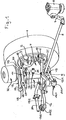
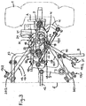
- part of the front axle shown is 1 with a steerable, air-sprung wheel and 2 with the wheel carrier supporting it.
- the latter is pivoted about a kingpin 3 on a kingpin 4.
- This is articulated to the vehicle frame 5, which is only schematically indicated in the drawing, via a plurality of links.
- a steering gear 6 can be seen in the drawing, which acts via a lever arm 7, a steering rod 8 connected to it, a toggle lever 9 articulated thereon and a tie rod 10 on a steering lever 11 arranged fixed to the wheel carrier.
- a middle tie rod 12 connects the toggle lever 9 to the wheel side opposite the axle side.
- the steering knuckle 4 can be realized to achieve high torsional rigidity as a cast, profiled hollow body made of cast steel or nodular cast iron, for example. Details and details of a steering knuckle support 4 cast in this way can be seen from FIGS. 6 to 9. In it, 4/1 designate the outer wall and 4/2 the enclosed cavity of the steering knuckle 4. 4/3 are cast iron eyes. Alternatively, the steering knuckle 4 can also be used as a die-forged part with a cross-sectional profile, e.g. B. made of tempered steel. Regardless of the non-cutting manufacturing method of its basic shape, the final shape of the axle body 4 is generated by appropriate machining post-processing of the blank at required locations.
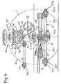
- the wishbone 13 with its V-shaped legs 13/1, 13/2 overlaps the protruding axle support 4 and is articulated with its thigh-knee area to the outside of the latter.
- the wishbone 13 with its thigh-knee region - as the examples according to FIGS. 10 and 11 show - can be articulated on a bearing member 34 projecting at the lower end of the stub axle 4. This has been discussed in more detail later.
- the wishbone 13 is articulated on the inside of the leg as well as in the knee area of its legs 13/1, 13/2 via a spherical molecular spherical plain bearing 17/1, 17/2, 17/3 on the vehicle frame 5 or steering knuckle support 4.
- the two legs 13/1, 13/2 of the wishbone 13 each have a bearing eye 20/1 and 20/2 on the inside.
- a maintenance-free spherical molecular bearing is installed in each of these as part of a molecular ball claw spherical plain bearing 17/1 or 17/2 extending in the horizontal plane.
- the wishbone 13 is articulated to the vehicle frame 5 via the outer claws of the two spherical bearings 17/1, 17/2, and corresponding bearing blocks (not shown) there.
- the wishbone 13 also has a bearing eye 21 with a built-in maintenance-free spherical molecular bearing.
- this is part of a vertically extending molecular ball claw joint bearing 17/3, via the outer, vertically arranged claws of which the wishbone 13 is articulated on the outside of the steering knuckle 4.
- the latter has a wall-shaped indentation 22 in its lower region, into which the wishbone 13 with its bearing eye 21 is partially immersed.
- Above and below the indentation 22 there are 4 contact surfaces 23 for supporting the claws of the spherical plain bearing 17/3 and threaded bores 23/1 for fixing the same to the steering knuckle support by means of screws.
- the wishbone 13 with the maintenance-free spherical molecular bearing 17/3 installed in its bearing eye 21 is fastened to a conical bearing journal 34/1 via a conical bore formed therein.
- This part of the bearing member 34 forming tapered bearing journal 34/1 is attached to the lower end of the steering knuckle 4, projecting vertically downward.
- the bearing journal 34/1 is part of a double tapered bolt which, with its upper conical bolt section 34/2, dips into a conical bore formed at the bottom of the steering knuckle 4 and is locked in this in a positive and non-positive manner with a screw 34/3 is, which at the same time for the permanent storage of camp 17/3 on tapered bearing journal 34/1 is used.
- the tapered journal 34/1 is part of a holding plate 34/4 which is fastened to the lower end of the steering knuckle 4 by means of screws 34/5.
- the bearing 17/3 is in this case clamped by means of a screw 34/6 on the tapered bearing journal 34/1.
- Each of the two identical wishbones 14, 15 has an inner-end bearing eye 24 and an outer-end bearing eye 25, each with a through-hole running transversely to the longitudinal direction of the handlebar, in each of which a rotatable, cylindrical molecular bushing bearing 18 is installed with its cylindrical slot bushing.
- Tapered sleeves 26 are each supported on the mutually facing end faces of the slotted bushings on the inside of the handlebar, and also on the facing faces of the slotted bushings on the outside of the handlebar. These engage in corresponding conical bore sections which are formed in pairs opposite one another at the ends of a through bore in a frame-fixed bearing block (not shown) and on the other hand a through bore 27 in the upper region of the steering knuckle 4.
- a tie rod which penetrates the two inner-end molecular bearing slot bushings, the two tapered sleeves 26 supported thereon and the through-bore having the associated conical bore sections on the frame-side bearing block (not shown) and for the inner-end fastening of the two wishbones 14, 15 to the vehicle frame 5 serves.
- a tie rod arranged parallel to the tie rod 28 is designated, which penetrates the two outer-end molecular bearing slot bushings, the two tapered sleeves 26 supported thereon and the through-bore 27 in the steering knuckle support 4 which has the associated conical bore sections and for the outer-end fastening of the two wishbones 14, 15 on Stub axle 4 is used.
- the two links 14, 15 are each clamped from the outside by corresponding axial prestressing of each of the two tie rods 28, 29 to the bearing block or steering knuckle 4, the axial force being applied via the two molecular bearing slot bushings each seated on one of the tie rods 28, 29 to which cone sleeves 26 pressed in this way with high frictional force are transmitted.
- the trailing arm 16 which serves to stabilize the steering knuckle 4 in the longitudinal direction of the vehicle, is arranged in a horizontal plane that extends parallel to that receiving the wishbone 13, but is moved close to the upper wishbones 14, 15 just below (as shown) or above it.
- the trailing arm 16 can extend obliquely or parallel to the longitudinal axis of the vehicle in front of or behind the axle body 4, either under tension or pressure, in the horizontal plane.
- the trailing arm 16 has a bearing eye 30 and 31 at each of its two ends, each with a through hole running transversely to the longitudinal direction of the trailing arm, into each of which a molecular bushing bearing 19/1 or 19/2 with its cylindrical slot bushing is installed .
- connection of the trailing arm 16 to the upper region of the steering knuckle 4 is established, with corresponding contact surfaces 4/3 (see FIG. 6) for supporting the claws and threaded bores for fixing the latter are given on it via screws.
- the connection of the trailing arm 16 to a bearing block (not shown) fixed to the vehicle frame is established via the claws with associated screws of the other molecular bushing bearing 19/2.
- the links 14, 15, 16 are preferably each realized by a one-piece drop-forged part, but can also be represented as a cast part, the blank being machined accordingly at the necessary points after being removed from the mold.
- a stabilizer 37 which reduces the side tilt of the vehicle in curves and its sensitivity to side winds, as well as the roll behavior improved.
- a stabilizer 37 can be U-shaped in plan view, connect the two steering knuckle supports 4 provided for each axle in an articulated manner and can be suspended on the vehicle frame 5 via rockers or bearing blocks (not shown). The connection point on the steering knuckle is given by the 4/6 organ there.
- the momentary center of the axle is at the level of the roadway, which means that the lateral force lever arm responsible for the disturbing lateral acceleration is missing in some wheel suspensions.
- Body lateral accelerations can therefore be effectively avoided in a vehicle with the independent wheel suspension according to the invention.
- the entire axle guide, but especially the bearings themselves, keep road noise away from the vehicle body, are maintenance-free and practically wear-free, hardly flexible, yet easily rotatable and precise.
- the lower wishbone 13 because of its large projection length and the relatively small angle of rotation, is equipped with three molecular ball claw spherical bearings that are adapted to the loads that occur, cylindrical molecular slot bush bearings are used for the dissolved upper link system 14, 15, 16.
Landscapes
- Engineering & Computer Science (AREA)
- Mechanical Engineering (AREA)
- Chemical & Material Sciences (AREA)
- Combustion & Propulsion (AREA)
- Transportation (AREA)
- Vehicle Body Suspensions (AREA)
- Automobile Manufacture Line, Endless Track Vehicle, Trailer (AREA)
Applications Claiming Priority (2)
| Application Number | Priority Date | Filing Date | Title |
|---|---|---|---|
| DE19619189 | 1996-05-11 | ||
| DE19619189A DE19619189A1 (de) | 1996-05-11 | 1996-05-11 | Einzelradaufhängung für ein luftgefedertes, lenkbares Rad eines Omnibusses oder Lastkraftwagen |
Publications (3)
| Publication Number | Publication Date |
|---|---|
| EP0806310A2 true EP0806310A2 (fr) | 1997-11-12 |
| EP0806310A3 EP0806310A3 (fr) | 1999-05-12 |
| EP0806310B1 EP0806310B1 (fr) | 2001-11-28 |
Family
ID=7794143
Family Applications (1)
| Application Number | Title | Priority Date | Filing Date |
|---|---|---|---|
| EP97104006A Expired - Lifetime EP0806310B1 (fr) | 1996-05-11 | 1997-03-11 | Suspension indépendante pour une roue directrice à suspension pneumatique d'un autobus ou camion |
Country Status (5)
| Country | Link |
|---|---|
| EP (1) | EP0806310B1 (fr) |
| DE (2) | DE19619189A1 (fr) |
| ES (1) | ES2163675T3 (fr) |
| HU (1) | HU223132B1 (fr) |
| TR (1) | TR199700336A2 (fr) |
Cited By (12)
| Publication number | Priority date | Publication date | Assignee | Title |
|---|---|---|---|---|
| WO1999030956A1 (fr) * | 1997-12-12 | 1999-06-24 | Holland Neway International, Inc. | Suspension avant independante |
| WO2001028791A1 (fr) * | 1999-10-18 | 2001-04-26 | Volvo Lastvagnar Ab | Suspension de roue independante |
| EP1213206A2 (fr) | 2000-12-09 | 2002-06-12 | ZF FRIEDRICHSHAFEN Aktiengesellschaft | Dispositif de direction pour roues avant dirigeables |
| WO2002053447A3 (fr) * | 2000-12-28 | 2003-01-03 | Dana Corp | Sous-cadre de suspension avant independante modulaire |
| US6783137B2 (en) | 2002-11-14 | 2004-08-31 | Tuthill Corporation | Steering knuckle carrier-to-suspension arm pivotal connection and method of assembling and preloading the pivotal connection |
| GB2405381A (en) * | 2003-09-01 | 2005-03-02 | Ford Global Tech Llc | Five-link vehicle suspension system |
| WO2007012324A1 (fr) * | 2005-07-28 | 2007-02-01 | Zf Friedrichshafen Ag | Chassis de vehicule automobile |
| FR2914586A1 (fr) * | 2007-04-03 | 2008-10-10 | Renault Sas | Train arriere multi-bras pour vehicule automobile |
| EP2351656A1 (fr) * | 2010-01-12 | 2011-08-03 | MAN Truck & Bus AG | Véhicule utilitaire doté d'une liaison de bras triangulaires |
| WO2014114087A1 (fr) * | 2013-01-25 | 2014-07-31 | 安徽江淮汽车股份有限公司 | Ensemble ressort de guidage pour suspension aérienne |
| CN105059074A (zh) * | 2015-09-08 | 2015-11-18 | 北京航天发射技术研究所 | 具有过载保护功能的悬架限位器、悬架系统和车辆 |
| CN113635722A (zh) * | 2021-08-16 | 2021-11-12 | 西南交通大学 | 一种适用于轮毂电机驱动虚拟轨道列车的半主动悬架系统 |
Families Citing this family (4)
| Publication number | Priority date | Publication date | Assignee | Title |
|---|---|---|---|---|
| DE10007192C2 (de) * | 2000-02-17 | 2002-10-24 | Benteler Werke Ag | Lenker für Kraftfahrzeuge |
| DE10061407A1 (de) * | 2000-12-09 | 2002-06-13 | Zahnradfabrik Friedrichshafen | Einzelradaufhängung für ein gefedertes, lenkbares Rad |
| ITTO20020268A1 (it) * | 2002-03-26 | 2003-09-26 | Iveco Fiat | Sospensione indipendente per una ruota di un veicolo industriale. |
| DE102006031708A1 (de) * | 2006-07-08 | 2008-01-10 | Daimlerchrysler Ag | Verfahren zur Herstellung eines Achsschenkels |
Family Cites Families (12)
| Publication number | Priority date | Publication date | Assignee | Title |
|---|---|---|---|---|
| US2934352A (en) * | 1956-11-19 | 1960-04-26 | Gen Motors Corp | Vehicle fluid suspension |
| FR1232152A (fr) * | 1958-08-12 | 1960-10-06 | Guy Motors Ltd | Suspension pour véhicules à roues directrices indépendantes |
| AT295337B (de) * | 1968-08-20 | 1971-12-27 | Bayerische Motoren Werke Ag | Unabhängige Aufhängung der gelenkten Räder von Kraftfahrzeugen, insbesondere Personenkraftwagen |
| BE789857A (fr) * | 1971-10-13 | 1973-02-01 | Carrozzeria | Suspension pneumatique avant a roues independantes pour des autobus et vehicules industriels |
| DE2624704B1 (de) * | 1976-06-02 | 1978-04-27 | Georg Fischer Ag, Schaffhausen (Schweiz) | Einteiliges, als Gußteil ausgebildetes Schwenklager für ein gelenktes Fahrzeugrad |
| DE2918605A1 (de) * | 1979-05-09 | 1980-11-13 | Daimler Benz Ag | Einzelradaufhaengung mittels uebereinander angeordneter fuehrungslenker |
| DE3345952A1 (de) * | 1983-12-20 | 1985-06-27 | Fa. Gotthard Drögmöller, 7100 Heilbronn | Drehlagerverbindung zwischen federtraeger und querlenker bei einer kraftfahrzeug-vorderachsaufhaengung |
| JPS6121802A (ja) * | 1984-07-10 | 1986-01-30 | Nissan Motor Co Ltd | 車両用懸架装置 |
| DE3718137A1 (de) * | 1987-05-29 | 1988-12-15 | Man Nutzfahrzeuge Gmbh | Einzelradaufhaengung fuer ein lenkbares rad an einem nutzfahrzeug |
| DE4017210C1 (fr) * | 1990-05-29 | 1991-10-31 | Mercedes-Benz Aktiengesellschaft, 7000 Stuttgart, De | |
| FR2675431B1 (fr) * | 1991-04-16 | 1993-07-16 | Renault | Dispositif de suspension de vehicule a jambe articulee. |
| FR2707926B1 (fr) * | 1993-06-29 | 1995-10-06 | Peugeot | Dispositif de suspension perfectionné pour une roue avant de véhicule automobile. |
-
1996
- 1996-05-11 DE DE19619189A patent/DE19619189A1/de not_active Withdrawn
-
1997
- 1997-03-11 EP EP97104006A patent/EP0806310B1/fr not_active Expired - Lifetime
- 1997-03-11 ES ES97104006T patent/ES2163675T3/es not_active Expired - Lifetime
- 1997-03-11 DE DE59705492T patent/DE59705492D1/de not_active Expired - Lifetime
- 1997-03-21 HU HU9700626A patent/HU223132B1/hu active IP Right Grant
- 1997-05-01 TR TR97/00336A patent/TR199700336A2/xx unknown
Cited By (21)
| Publication number | Priority date | Publication date | Assignee | Title |
|---|---|---|---|---|
| CN1100689C (zh) * | 1997-12-12 | 2003-02-05 | 荷兰新维国际有限公司 | 独立前悬挂系统 |
| US6116626A (en) * | 1997-12-12 | 2000-09-12 | Holland Neway International, Inc. | Independent front suspension |
| AU738852B2 (en) * | 1997-12-12 | 2001-09-27 | Holland Neway International, Inc. | Independent front suspension |
| AU738852C (en) * | 1997-12-12 | 2003-04-10 | Holland Neway International, Inc. | Independent front suspension |
| WO1999030956A1 (fr) * | 1997-12-12 | 1999-06-24 | Holland Neway International, Inc. | Suspension avant independante |
| WO2001028791A1 (fr) * | 1999-10-18 | 2001-04-26 | Volvo Lastvagnar Ab | Suspension de roue independante |
| US6685203B1 (en) | 1999-10-18 | 2004-02-03 | Volvo Lastvagner Ab | Individual wheel suspension |
| EP1213206A2 (fr) | 2000-12-09 | 2002-06-12 | ZF FRIEDRICHSHAFEN Aktiengesellschaft | Dispositif de direction pour roues avant dirigeables |
| EP1559635A1 (fr) | 2000-12-09 | 2005-08-03 | Zf Friedrichshafen Ag | Dispositif de direction pour roues avant dirigeables |
| WO2002053447A3 (fr) * | 2000-12-28 | 2003-01-03 | Dana Corp | Sous-cadre de suspension avant independante modulaire |
| US7380831B2 (en) | 2000-12-28 | 2008-06-03 | Dana Heavy Vehicle Systems Group, Llc | Modular cast independent front suspension subframe |
| US6866295B2 (en) | 2000-12-28 | 2005-03-15 | Dana Corporation | Modular cast independent front suspension subframe |
| US6783137B2 (en) | 2002-11-14 | 2004-08-31 | Tuthill Corporation | Steering knuckle carrier-to-suspension arm pivotal connection and method of assembling and preloading the pivotal connection |
| GB2405381A (en) * | 2003-09-01 | 2005-03-02 | Ford Global Tech Llc | Five-link vehicle suspension system |
| WO2007012324A1 (fr) * | 2005-07-28 | 2007-02-01 | Zf Friedrichshafen Ag | Chassis de vehicule automobile |
| FR2914586A1 (fr) * | 2007-04-03 | 2008-10-10 | Renault Sas | Train arriere multi-bras pour vehicule automobile |
| WO2008129211A1 (fr) * | 2007-04-03 | 2008-10-30 | Renault S.A.S | Train arriere multi-bras pour vehicule automobile |
| EP2351656A1 (fr) * | 2010-01-12 | 2011-08-03 | MAN Truck & Bus AG | Véhicule utilitaire doté d'une liaison de bras triangulaires |
| WO2014114087A1 (fr) * | 2013-01-25 | 2014-07-31 | 安徽江淮汽车股份有限公司 | Ensemble ressort de guidage pour suspension aérienne |
| CN105059074A (zh) * | 2015-09-08 | 2015-11-18 | 北京航天发射技术研究所 | 具有过载保护功能的悬架限位器、悬架系统和车辆 |
| CN113635722A (zh) * | 2021-08-16 | 2021-11-12 | 西南交通大学 | 一种适用于轮毂电机驱动虚拟轨道列车的半主动悬架系统 |
Also Published As
| Publication number | Publication date |
|---|---|
| HUP9700626A2 (hu) | 1998-11-30 |
| EP0806310B1 (fr) | 2001-11-28 |
| HU9700626D0 (en) | 1997-05-28 |
| EP0806310A3 (fr) | 1999-05-12 |
| HU223132B1 (hu) | 2004-03-29 |
| HUP9700626A3 (en) | 2000-02-28 |
| TR199700336A3 (tr) | 1998-10-21 |
| ES2163675T3 (es) | 2002-02-01 |
| DE19619189A1 (de) | 1997-11-13 |
| TR199700336A2 (xx) | 1998-10-21 |
| DE59705492D1 (de) | 2002-01-10 |
Similar Documents
| Publication | Publication Date | Title |
|---|---|---|
| EP0656270B1 (fr) | Suspension de roue | |
| EP0141092B1 (fr) | Suspension de roue indépendante pour véhicules automobiles | |
| DE102004058698B3 (de) | Radaufhängung mit Federverstellung für Kraftfahrzeuge | |
| DE60125410T2 (de) | Fahrzeugaufhängungssystem | |
| DE3635612C2 (fr) | ||
| DE10053411B4 (de) | Fahrzeugachse | |
| DE19743736B4 (de) | Vorderradaufhängung | |
| EP0806310B1 (fr) | Suspension indépendante pour une roue directrice à suspension pneumatique d'un autobus ou camion | |
| EP1404536A1 (fr) | Essieu arriere d'un vehicule automobile dote de cinq bras oscillants | |
| DE102016220786B4 (de) | Hinterradaufhängung für Kraftfahrzeuge | |
| EP1080953A1 (fr) | Suspension de roue d'un véhicule automobile à ressort à lame guidant la roue | |
| DE3514788A1 (de) | Radaufhaengung | |
| DE3331282A1 (de) | Radaufhaengung fuer lenkbare vorderraeder von kraftfahrzeugen | |
| EP0199189A1 (fr) | Suspension indépendante d'essieu de véhicule | |
| DE102006044151A1 (de) | Einzelradaufhängung vom Doppelquerlenker-Typ | |
| WO2020038855A1 (fr) | Essieu arrière d'un véhicule | |
| EP0873891A2 (fr) | Suspension indépendante pour roues directrices de véhicules à moteur, en particlierr de voitures automobiles | |
| EP1592570A1 (fr) | Suspension de roue destinee a des vehicules | |
| DE60306730T2 (de) | Lenkeinrichtung für die Trage-Einrichtung der Hinterradnabe in Motorfahrzeugen | |
| EP0452835A1 (fr) | Essieu arrière d'un véhicule automobile | |
| DE4136276B4 (de) | Vorderradaufhängung | |
| EP0464415B1 (fr) | Suspension à bras longitudinaux pour véhicules à moteur et remorques | |
| DE69325134T2 (de) | Hinterradaufhängung für Kraftfahrzeug mit unabhängigen Rädern | |
| DE102017211277A1 (de) | Radaufhängung für ein Kraftfahrzeug | |
| DE19535923B4 (de) | Unabhängige Radaufhängung für angetriebene Hinterräder von Kraftfahrzeugen |
Legal Events
| Date | Code | Title | Description |
|---|---|---|---|
| PUAI | Public reference made under article 153(3) epc to a published international application that has entered the european phase |
Free format text: ORIGINAL CODE: 0009012 |
|
| AK | Designated contracting states |
Kind code of ref document: A2 Designated state(s): BE DE ES FR IT NL |
|
| PUAL | Search report despatched |
Free format text: ORIGINAL CODE: 0009013 |
|
| AK | Designated contracting states |
Kind code of ref document: A3 Designated state(s): BE DE ES FR IT NL |
|
| 17P | Request for examination filed |
Effective date: 19990616 |
|
| GRAG | Despatch of communication of intention to grant |
Free format text: ORIGINAL CODE: EPIDOS AGRA |
|
| 17Q | First examination report despatched |
Effective date: 20010302 |
|
| GRAG | Despatch of communication of intention to grant |
Free format text: ORIGINAL CODE: EPIDOS AGRA |
|
| GRAH | Despatch of communication of intention to grant a patent |
Free format text: ORIGINAL CODE: EPIDOS IGRA |
|
| GRAH | Despatch of communication of intention to grant a patent |
Free format text: ORIGINAL CODE: EPIDOS IGRA |
|
| ITF | It: translation for a ep patent filed | ||
| GRAA | (expected) grant |
Free format text: ORIGINAL CODE: 0009210 |
|
| AK | Designated contracting states |
Kind code of ref document: B1 Designated state(s): BE DE ES FR IT NL |
|
| REF | Corresponds to: |
Ref document number: 59705492 Country of ref document: DE Date of ref document: 20020110 |
|
| REG | Reference to a national code |
Ref country code: ES Ref legal event code: FG2A Ref document number: 2163675 Country of ref document: ES Kind code of ref document: T3 |
|
| ET | Fr: translation filed | ||
| PLBE | No opposition filed within time limit |
Free format text: ORIGINAL CODE: 0009261 |
|
| STAA | Information on the status of an ep patent application or granted ep patent |
Free format text: STATUS: NO OPPOSITION FILED WITHIN TIME LIMIT |
|
| 26N | No opposition filed | ||
| REG | Reference to a national code |
Ref country code: NL Ref legal event code: TD Effective date: 20110420 |
|
| REG | Reference to a national code |
Ref country code: FR Ref legal event code: CD |
|
| REG | Reference to a national code |
Ref country code: ES Ref legal event code: PC2A Owner name: "MAN TRUCK & Effective date: 20110620 Ref country code: ES Ref legal event code: PC2A Owner name: MAN TRUCK & BUS AG Effective date: 20110620 |
|
| REG | Reference to a national code |
Ref country code: DE Ref legal event code: R081 Ref document number: 59705492 Country of ref document: DE Owner name: MAN TRUCK & BUS AG, DE Free format text: FORMER OWNER: MAN NUTZFAHRZEUGE AG, 80995 MUENCHEN, DE Effective date: 20110518 |
|
| REG | Reference to a national code |
Ref country code: FR Ref legal event code: PLFP Year of fee payment: 20 |
|
| PGFP | Annual fee paid to national office [announced via postgrant information from national office to epo] |
Ref country code: NL Payment date: 20160324 Year of fee payment: 20 |
|
| PGFP | Annual fee paid to national office [announced via postgrant information from national office to epo] |
Ref country code: FR Payment date: 20160331 Year of fee payment: 20 Ref country code: BE Payment date: 20160324 Year of fee payment: 20 |
|
| PGFP | Annual fee paid to national office [announced via postgrant information from national office to epo] |
Ref country code: DE Payment date: 20160531 Year of fee payment: 20 Ref country code: ES Payment date: 20160422 Year of fee payment: 20 |
|
| PG25 | Lapsed in a contracting state [announced via postgrant information from national office to epo] |
Ref country code: IT Free format text: LAPSE BECAUSE OF NON-PAYMENT OF DUE FEES Effective date: 20160311 |
|
| REG | Reference to a national code |
Ref country code: DE Ref legal event code: R071 Ref document number: 59705492 Country of ref document: DE |
|
| REG | Reference to a national code |
Ref country code: NL Ref legal event code: MK Effective date: 20170310 |
|
| PG25 | Lapsed in a contracting state [announced via postgrant information from national office to epo] |
Ref country code: IT Free format text: LAPSE BECAUSE OF NON-PAYMENT OF DUE FEES Effective date: 20160311 |
|
| PGFP | Annual fee paid to national office [announced via postgrant information from national office to epo] |
Ref country code: IT Payment date: 20160325 Year of fee payment: 20 |
|
| PGRI | Patent reinstated in contracting state [announced from national office to epo] |
Ref country code: IT Effective date: 20170710 |
|
| REG | Reference to a national code |
Ref country code: ES Ref legal event code: FD2A Effective date: 20180508 |
|
| PG25 | Lapsed in a contracting state [announced via postgrant information from national office to epo] |
Ref country code: ES Free format text: LAPSE BECAUSE OF EXPIRATION OF PROTECTION Effective date: 20170312 |