EP0452835A1 - Essieu arrière d'un véhicule automobile - Google Patents
Essieu arrière d'un véhicule automobile Download PDFInfo
- Publication number
- EP0452835A1 EP0452835A1 EP91105925A EP91105925A EP0452835A1 EP 0452835 A1 EP0452835 A1 EP 0452835A1 EP 91105925 A EP91105925 A EP 91105925A EP 91105925 A EP91105925 A EP 91105925A EP 0452835 A1 EP0452835 A1 EP 0452835A1
- Authority
- EP
- European Patent Office
- Prior art keywords
- stabilizer
- recess
- wheel
- stabiliser
- rear axle
- Prior art date
- Legal status (The legal status is an assumption and is not a legal conclusion. Google has not performed a legal analysis and makes no representation as to the accuracy of the status listed.)
- Granted
Links
Images
Classifications
-
- B—PERFORMING OPERATIONS; TRANSPORTING
- B60—VEHICLES IN GENERAL
- B60G—VEHICLE SUSPENSION ARRANGEMENTS
- B60G21/00—Interconnection systems for two or more resiliently-suspended wheels, e.g. for stabilising a vehicle body with respect to acceleration, deceleration or centrifugal forces
- B60G21/02—Interconnection systems for two or more resiliently-suspended wheels, e.g. for stabilising a vehicle body with respect to acceleration, deceleration or centrifugal forces permanently interconnected
- B60G21/04—Interconnection systems for two or more resiliently-suspended wheels, e.g. for stabilising a vehicle body with respect to acceleration, deceleration or centrifugal forces permanently interconnected mechanically
- B60G21/05—Interconnection systems for two or more resiliently-suspended wheels, e.g. for stabilising a vehicle body with respect to acceleration, deceleration or centrifugal forces permanently interconnected mechanically between wheels on the same axle but on different sides of the vehicle, i.e. the left and right wheel suspensions being interconnected
- B60G21/051—Trailing arm twist beam axles
-
- B—PERFORMING OPERATIONS; TRANSPORTING
- B60—VEHICLES IN GENERAL
- B60G—VEHICLE SUSPENSION ARRANGEMENTS
- B60G11/00—Resilient suspensions characterised by arrangement, location or kind of springs
- B60G11/18—Resilient suspensions characterised by arrangement, location or kind of springs having torsion-bar springs only
- B60G11/20—Resilient suspensions characterised by arrangement, location or kind of springs having torsion-bar springs only characterised by means specially adapted for attaching the spring to axle or sprung part of the vehicle
-
- B—PERFORMING OPERATIONS; TRANSPORTING
- B60—VEHICLES IN GENERAL
- B60G—VEHICLE SUSPENSION ARRANGEMENTS
- B60G2200/00—Indexing codes relating to suspension types
- B60G2200/20—Semi-rigid axle suspensions
- B60G2200/21—Trailing arms connected by a torsional beam, i.e. twist-beam axles
-
- B—PERFORMING OPERATIONS; TRANSPORTING
- B60—VEHICLES IN GENERAL
- B60G—VEHICLE SUSPENSION ARRANGEMENTS
- B60G2200/00—Indexing codes relating to suspension types
- B60G2200/20—Semi-rigid axle suspensions
- B60G2200/22—Trailing arms connected by a straight torsion bar
-
- B—PERFORMING OPERATIONS; TRANSPORTING
- B60—VEHICLES IN GENERAL
- B60G—VEHICLE SUSPENSION ARRANGEMENTS
- B60G2202/00—Indexing codes relating to the type of spring, damper or actuator
- B60G2202/10—Type of spring
- B60G2202/13—Torsion spring
- B60G2202/136—Twist-beam type arrangement
- B60G2202/1362—Twist-beam type arrangement including a second torsional element, e.g. second beam, stabiliser bar or tube
-
- B—PERFORMING OPERATIONS; TRANSPORTING
- B60—VEHICLES IN GENERAL
- B60G—VEHICLE SUSPENSION ARRANGEMENTS
- B60G2206/00—Indexing codes related to the manufacturing of suspensions: constructional features, the materials used, procedures or tools
- B60G2206/01—Constructional features of suspension elements, e.g. arms, dampers, springs
- B60G2206/20—Constructional features of semi-rigid axles, e.g. twist beam type axles
- B60G2206/201—Constructional features of semi-rigid axles, e.g. twist beam type axles with detachable cross beam and/or torsion stabiliser bar/tube
Definitions
- the invention relates to a motor vehicle rear axle of the composite or coupling arm type with pivotally articulated wheel-supporting longitudinal links in sheet metal shell construction of the type mentioned in the preamble of claim 1, as is known for example from DE-OS 24 24 649.
- Torsion bar springs lying transversely to the longitudinal direction of the vehicle are used as stabilizers, their ends acting on the trailing arms of the torsion-beam axis.
- the stabilizer ends of U-type stabilizers are generally using two spaced rubber elements on the trailing arms - mostly from below - screwed, for which the wall thickness must be dimensioned sufficiently thick at least in these areas.
- Stabilizer arrangements of this type have the advantage in themselves that the torsion beam axles with different stabilizers required for a certain vehicle type due to the diverse equipment variants common today, particularly with regard to the motorization, can in principle be manufactured using identical axle welded bodies (welded longitudinal link / cross strut composite) , to which only differently dimensioned U-shape stabilizers are screwed.
- this type of connection of the stabilizer ends is not only relatively expensive because of the fourfold rubber mounting, but also requires a comparatively long assembly time.
- the stabilizer ends of stabilizers of the linear type are usually welded directly into the sheet metal walls of the trailing arms. It is easy to see that the thin-walled trailing arms are highly stressed in the area of the welded-in stabilizer ends and that this stress increases with the size of the stabilizer required, i.e. with the size of the stabilizer torsional moment or with the size of the stabilizer forces introduced into the trailing arm .
- the invention is based on the object of designing a motor vehicle rear axle of the composite or coupling arm type of the type mentioned in the preamble of claim 1 in such a way that on the one hand the use of - in comparison to U-shape stabilizers light - large-dimensioned stabilizers designed as straight torsion bars also is possible in connection with weight-optimized thin-walled handlebar plate shells, and that on the other hand the manufacturing and control expenditure for the production of torsion beam axles differing essentially only by the size of the built-in stabilizer is kept low or even reduced.
- the stabilizer ends of the rectilinear stabilizer are no longer welded directly into the thin-walled sheet metal shells of the trailing arms, but are inserted positively or non-positively into rigid connecting rod-like coupling links which lie in the end region of the trailing arm shell body on the body side and introduce the stabilizer forces into the trailing arms.
- torsion beam axles with comparatively light, thin-walled sheet metal trailing arms can be easily used with straight-line stabilizers any diameter can be equipped, without this requiring a structural differentiation of the actual axle weld body (trailing arm / transverse strut assembly); only the rigid coupling links in the body-side end area of the trailing arm shell body must be matched to the differently dimensioned stabilizer ends of the various stabilizer types with regard to their recesses receiving the stabilizer ends, provided that the stabilizer forces - for whatever reason - are not of identical design.
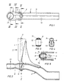
- the torsion beam axle 1 shown consists in the usual manner of two wheel-carrying longitudinal links 2 of sheet metal construction, which can be pivoted to the vehicle body (not shown) - only one of which is shown - and one torsionally rigid transverse strut 4 connecting the two longitudinal links near their body-side link bearings 3.
- the shell bodies 7 of the trailing arms 2 are composed of an upper and a lower sheet metal shell 71, 72 which are welded to one another and to the end of the cross strut 4 which engages them.
- a with its ends on the trailing arms 2 acting transversely to the vehicle longitudinal axis stabilizer 5 in the manner of a straight torsion bar is arranged at the level of the cross strut 4 designed in the exemplary embodiment as open in the direction of travel V-strut 4.
- the stabilizer ends 6 are not connected to the trailing arms 2 by welding directly into the sheet metal shells, but rather by means of a rigid connecting rod-like coupling element 8 which is inserted in the end region of the shell body 7 of the trailing arm 2 concerned.
- the coupling member 8 has a recess 81 on its wheel-side end approximately at the level of the cross strut 4 and a circular cylindrical recess 82 in its embodiment on the body end.
- the stabilizer 5 with its stabilizer end 6 is inserted into the wheel-side recess 81, the connection between the stabilizer end 6 and the recess 81 of the coupling member 8 preferably being made in a form-fitting manner. In principle, however, a non-positive or frictional connection between these two components is also conceivable.
- the circular cylindrical recess 82 on the body side of the coupling member serves to receive the e.g. as a rubber-metal bearing according to the type of DE-PS 28 38 391 trained, not shown in detail handlebar bearing 3.
- the handlebar bearing is preferably pressed into the recess.
- the coupling member 8 is at least non-positively connected to the shell body 7 of the trailing arm which surrounds it, at least in its end region containing the recess 82 on the body side. Because of the comparatively large support base (lever arm of the coupling element 8) for the torsional moments of the stabilizer 5 introduced into the coupling element 8, only relatively small forces result in the area of the front recess 82 of the coupling element, which forces are introduced into the shell-shaped trailing arm 2 with only slight surface pressure over the outer circumference of the body-side end of the coupling element 8 will. This results in the possibility of producing the shell bodies 7 of the trailing arms 2 from comparatively thin-walled sheet metal shells, which leads to a significant weight saving.
- the wheel-side recesses 81 of the coupling members 8 and the stabilizer ends 6 inserted therein have a coordinated contour, preferably a polygonal contour, which is different from the circular shape in order to produce a positive fit.
- the stabilizer 5 - as can be seen in FIGS. 2 and 5 - also has a cross-sectional shape which enables it to be installed and / or removed in the twist beam axis in its entire length through the wheel-side recess 81 of the coupling member 8 push through; this ultimately means that the diameter of the central part of the stabilizer 5, which is generally designed as a round rod and is subject to torsion, is at least somewhat smaller than the core diameter of the e.g. as a polygonal stabilizer ends 6.
- the stabilizer 5 must of course be secured against unwanted axial sliding out in such a design, which is done in the embodiment by screwed onto the stabilizer ends lock washers 9.
- the stabilizer forces are introduced directly into the pressed-in link bearing 3; the thin-walled shell body 7 itself remain essentially unloaded, so that the wall thickness of the sheet metal body essentially exclusively below Viewpoint of the maximum forces that occur operationally on the wheels can be measured.
- the pressing of the link bearings 3 into the body-side recess 82 of the coupling element 8, which is preferably designed as a cast body, is completely unproblematic. In contrast, the pressing of such handlebar bearings into thin-walled sheet metal shell bodies is comparatively difficult because it may result in minor bulging and warping of the sheet metal shell.
- the coupling member 8 is built into the one sheet metal shell, e.g. is placed in the lower sheet metal shell 72, then the upper sheet metal shell 71 is placed on it and then both shells are welded together; the coupling member is in the area of its body-side recess 82 i.a. stretched sufficiently firmly between the two welded shells 71, 72 (press connection).
- the motor vehicle rear axle according to the invention makes it possible in a simple manner to use the same longitudinal links of torsion beam axles or the like, which are manufactured in thin-walled sheet metal shell construction.
- Linking the stabilizer ends of very differently dimensioned rod-shaped stabilizers which is a great advantage in terms of control technology in the production of series vehicles whose rear axles must be equipped with different stabilizers due to the corresponding equipment variants, since despite the wide range of stabilizers, a uniform axle weld body (trailing arm / transverse strut assembly) is used Can be found.
Landscapes
- Engineering & Computer Science (AREA)
- Mechanical Engineering (AREA)
- Vehicle Body Suspensions (AREA)
Applications Claiming Priority (2)
| Application Number | Priority Date | Filing Date | Title |
|---|---|---|---|
| DE4012401 | 1990-04-19 | ||
| DE4012401 | 1990-04-19 |
Publications (2)
| Publication Number | Publication Date |
|---|---|
| EP0452835A1 true EP0452835A1 (fr) | 1991-10-23 |
| EP0452835B1 EP0452835B1 (fr) | 1993-06-23 |
Family
ID=6404607
Family Applications (1)
| Application Number | Title | Priority Date | Filing Date |
|---|---|---|---|
| EP91105925A Expired - Lifetime EP0452835B1 (fr) | 1990-04-19 | 1991-04-13 | Essieu arrière d'un véhicule automobile |
Country Status (3)
| Country | Link |
|---|---|
| EP (1) | EP0452835B1 (fr) |
| DE (1) | DE59100162D1 (fr) |
| ES (1) | ES2042322T3 (fr) |
Cited By (10)
| Publication number | Priority date | Publication date | Assignee | Title |
|---|---|---|---|---|
| US5463557A (en) * | 1992-05-15 | 1995-10-31 | Kabushiki Kaisha Toyoda Jidoshokki Seisakusho | Roving machine |
| DE19605283A1 (de) * | 1995-02-13 | 1996-08-22 | Daihatsu Motor Co Ltd | Längslenkeraufhängung für Fahrzeuge |
| FR2761304A1 (fr) * | 1997-03-28 | 1998-10-02 | Peugeot | Train de roues arriere pour vehicule automobile a traverse deformable en torsion |
| US6533300B1 (en) | 2000-06-02 | 2003-03-18 | Oxford Suspension, Inc. | Trailing twist axle and method of manufacture |
| FR2846914A1 (fr) * | 2002-11-08 | 2004-05-14 | Auto Chassis Int | Renfort souple de barre anti-devers |
| FR2858585A1 (fr) * | 2003-08-08 | 2005-02-11 | Auto Chassis Int | Essieu souple pour vehicule automobile |
| EP1619056A1 (fr) * | 2004-07-21 | 2006-01-25 | Nissan Motor Company, Limited | Système de suspension de roue |
| CN100457486C (zh) * | 2004-07-21 | 2009-02-04 | 日产自动车株式会社 | 车轮悬架系统 |
| EP2357097A1 (fr) * | 2010-02-17 | 2011-08-17 | Cie Automotive, S.A. | Lenker für einen Drehstab sowie Drehstab |
| CN107985002A (zh) * | 2017-12-15 | 2018-05-04 | 阿尔特汽车技术股份有限公司 | 扭力梁焊接总成结构 |
Families Citing this family (3)
| Publication number | Priority date | Publication date | Assignee | Title |
|---|---|---|---|---|
| DE19542105B4 (de) * | 1994-11-22 | 2009-07-30 | Volkswagen Ag | Verbundlenker- oder Koppellenkerachse |
| DE102013217639A1 (de) * | 2013-09-04 | 2015-03-05 | Zf Friedrichshafen Ag | Verbundlenkerachse mit ein- und ausbaubarem Stabilisator |
| CN111114227B (zh) * | 2018-10-30 | 2021-09-21 | 长城汽车股份有限公司 | 扭力梁悬架结构 |
Citations (4)
| Publication number | Priority date | Publication date | Assignee | Title |
|---|---|---|---|---|
| FR2098846A5 (fr) * | 1970-07-29 | 1972-03-10 | Chrysler France | |
| EP0059126A1 (fr) * | 1981-02-25 | 1982-09-01 | Automobiles Peugeot | Dispositif d'ancrage d'une barre de torsion sur un bras oscillant en tôle |
| DE3521361A1 (de) * | 1984-07-10 | 1986-01-23 | Volkswagenwerk Ag, 3180 Wolfsburg | Verbund- oder koppellenker-hinterachse fuer kraftfahrzeuge |
| FR2618733A1 (fr) * | 1987-07-31 | 1989-02-03 | Peugeot | Essieu porteur de vehicule automobile |
-
1991
- 1991-04-13 EP EP91105925A patent/EP0452835B1/fr not_active Expired - Lifetime
- 1991-04-13 ES ES199191105925T patent/ES2042322T3/es not_active Expired - Lifetime
- 1991-04-13 DE DE9191105925T patent/DE59100162D1/de not_active Expired - Fee Related
Patent Citations (4)
| Publication number | Priority date | Publication date | Assignee | Title |
|---|---|---|---|---|
| FR2098846A5 (fr) * | 1970-07-29 | 1972-03-10 | Chrysler France | |
| EP0059126A1 (fr) * | 1981-02-25 | 1982-09-01 | Automobiles Peugeot | Dispositif d'ancrage d'une barre de torsion sur un bras oscillant en tôle |
| DE3521361A1 (de) * | 1984-07-10 | 1986-01-23 | Volkswagenwerk Ag, 3180 Wolfsburg | Verbund- oder koppellenker-hinterachse fuer kraftfahrzeuge |
| FR2618733A1 (fr) * | 1987-07-31 | 1989-02-03 | Peugeot | Essieu porteur de vehicule automobile |
Non-Patent Citations (1)
| Title |
|---|
| ATZ AUTOMOBILTECHNISCHE ZEITSCHRIFT, vol. 85, no. 9, September 1983, STUTTGART, DE; Seiten 509 - 511; F.W. Lohr: "Neuer Opel Corsa" * |
Cited By (15)
| Publication number | Priority date | Publication date | Assignee | Title |
|---|---|---|---|---|
| US5463557A (en) * | 1992-05-15 | 1995-10-31 | Kabushiki Kaisha Toyoda Jidoshokki Seisakusho | Roving machine |
| DE19605283B4 (de) * | 1995-02-13 | 2005-09-29 | Daihatsu Motor Co., Ltd., Ikeda | Längslenkeraufhängung für Fahrzeuge |
| DE19605283A1 (de) * | 1995-02-13 | 1996-08-22 | Daihatsu Motor Co Ltd | Längslenkeraufhängung für Fahrzeuge |
| FR2761304A1 (fr) * | 1997-03-28 | 1998-10-02 | Peugeot | Train de roues arriere pour vehicule automobile a traverse deformable en torsion |
| US6533300B1 (en) | 2000-06-02 | 2003-03-18 | Oxford Suspension, Inc. | Trailing twist axle and method of manufacture |
| FR2846914A1 (fr) * | 2002-11-08 | 2004-05-14 | Auto Chassis Int | Renfort souple de barre anti-devers |
| WO2004043718A1 (fr) * | 2002-11-08 | 2004-05-27 | Auto Chassis International | Renfort souple de barre anti-devers |
| FR2858585A1 (fr) * | 2003-08-08 | 2005-02-11 | Auto Chassis Int | Essieu souple pour vehicule automobile |
| WO2005023570A1 (fr) * | 2003-08-08 | 2005-03-17 | Auto Chassis International | Essieu souple pour vehicule automobile |
| EP1619056A1 (fr) * | 2004-07-21 | 2006-01-25 | Nissan Motor Company, Limited | Système de suspension de roue |
| CN100457486C (zh) * | 2004-07-21 | 2009-02-04 | 日产自动车株式会社 | 车轮悬架系统 |
| US7566063B2 (en) | 2004-07-21 | 2009-07-28 | Nissan Motor Co., Ltd. | Wheel suspension system |
| EP2357097A1 (fr) * | 2010-02-17 | 2011-08-17 | Cie Automotive, S.A. | Lenker für einen Drehstab sowie Drehstab |
| CN107985002A (zh) * | 2017-12-15 | 2018-05-04 | 阿尔特汽车技术股份有限公司 | 扭力梁焊接总成结构 |
| CN107985002B (zh) * | 2017-12-15 | 2024-03-08 | 阿尔特汽车技术股份有限公司 | 扭力梁焊接总成结构 |
Also Published As
| Publication number | Publication date |
|---|---|
| DE59100162D1 (de) | 1993-07-29 |
| ES2042322T3 (es) | 1993-12-01 |
| EP0452835B1 (fr) | 1993-06-23 |
Similar Documents
| Publication | Publication Date | Title |
|---|---|---|
| DE3243434C2 (de) | Unabhängige Radaufhängung für die Hinterräder eines Kraftfahrzeuges | |
| EP2155508B1 (fr) | Essieu arrière pour véhicule à moteur | |
| DE102014205632A1 (de) | Einzelradaufhängung sowie Hinterachse mit Einzelradaufhängungen für ein Fahrzeug und entsprechend ausgestattetes Fahrzeug | |
| EP0760750A1 (fr) | Suspension de roues avec amortisseur a ressort transversal a lame | |
| EP0452835B1 (fr) | Essieu arrière d'un véhicule automobile | |
| DE19933432B4 (de) | Radaufhängung bei einem Kraftfahrzeug | |
| EP3041693B1 (fr) | Essieu de torsion muni d'un stabilisateur démontable | |
| EP0806310B1 (fr) | Suspension indépendante pour une roue directrice à suspension pneumatique d'un autobus ou camion | |
| EP1541393B1 (fr) | Essieu de torsion | |
| WO2007087793A1 (fr) | Essieu entraîné à suspension indépendante sur un véhicule à moteur | |
| EP0352541B1 (fr) | Suspension élastique d'essieu pour véhicules automobiles, notamment pour véhicules utilitaires | |
| DE102014205635A1 (de) | Einzelradaufhängung sowie Hinterachse mit Einzelradaufhängungen für ein Fahrzeug und entsprechend ausgestattetes Fahrzeug | |
| WO2008061488A1 (fr) | Dispositif stabilisateur avec bielle de guidage de roue | |
| EP0464415B1 (fr) | Suspension à bras longitudinaux pour véhicules à moteur et remorques | |
| EP0940319A2 (fr) | Chassis d'un véhicule utilitaire lourd | |
| DE202014101432U1 (de) | Einzelradaufhängung sowie Hinterachse mit Einzelradaufhängungen für ein Fahrzeug und entsprechend ausgestattetes Fahrzeug | |
| EP1749678B1 (fr) | Corps d'essieu pour axes des véhicules utilitaires | |
| DE102017211277A1 (de) | Radaufhängung für ein Kraftfahrzeug | |
| EP0940322B1 (fr) | Chassis pour véhicule utilitaire lourd | |
| EP0940324B1 (fr) | Chassis pour véhicule utilitaire lourd | |
| DE102022000365B3 (de) | Koppellenkerachse in gekröpfter Ausführung für Fahrzeuge mit niedriger Ladeflächenhöhe und grossen Laufraddurchmessern | |
| EP0940323B1 (fr) | Chassis pour véhicule utilitaire lourd | |
| DE19853636B4 (de) | Radaufhängung | |
| EP0940325A1 (fr) | Chassis pour véhicule utilitaire lourd | |
| DE102022121454B3 (de) | Einzelradaufhängung eines zweispurigen Fahrzeugs |
Legal Events
| Date | Code | Title | Description |
|---|---|---|---|
| PUAI | Public reference made under article 153(3) epc to a published international application that has entered the european phase |
Free format text: ORIGINAL CODE: 0009012 |
|
| 17P | Request for examination filed |
Effective date: 19910808 |
|
| AK | Designated contracting states |
Kind code of ref document: A1 Designated state(s): DE ES FR GB IT |
|
| 17Q | First examination report despatched |
Effective date: 19921027 |
|
| GRAA | (expected) grant |
Free format text: ORIGINAL CODE: 0009210 |
|
| AK | Designated contracting states |
Kind code of ref document: B1 Designated state(s): DE ES FR GB IT |
|
| REF | Corresponds to: |
Ref document number: 59100162 Country of ref document: DE Date of ref document: 19930729 |
|
| RAP2 | Party data changed (patent owner data changed or rights of a patent transferred) |
Owner name: V O L K S W A G E N AKTIENGESELLSCHAFT |
|
| ET | Fr: translation filed | ||
| ITF | It: translation for a ep patent filed |
Owner name: MODIANO & ASSOCIATI S.R |
|
| GBT | Gb: translation of ep patent filed (gb section 77(6)(a)/1977) |
Effective date: 19930924 |
|
| REG | Reference to a national code |
Ref country code: ES Ref legal event code: FG2A Ref document number: 2042322 Country of ref document: ES Kind code of ref document: T3 |
|
| PLBE | No opposition filed within time limit |
Free format text: ORIGINAL CODE: 0009261 |
|
| STAA | Information on the status of an ep patent application or granted ep patent |
Free format text: STATUS: NO OPPOSITION FILED WITHIN TIME LIMIT |
|
| 26N | No opposition filed | ||
| PGFP | Annual fee paid to national office [announced via postgrant information from national office to epo] |
Ref country code: GB Payment date: 19960328 Year of fee payment: 6 |
|
| PGFP | Annual fee paid to national office [announced via postgrant information from national office to epo] |
Ref country code: FR Payment date: 19960416 Year of fee payment: 6 |
|
| PGFP | Annual fee paid to national office [announced via postgrant information from national office to epo] |
Ref country code: ES Payment date: 19960424 Year of fee payment: 6 |
|
| PG25 | Lapsed in a contracting state [announced via postgrant information from national office to epo] |
Ref country code: GB Effective date: 19970413 |
|
| PG25 | Lapsed in a contracting state [announced via postgrant information from national office to epo] |
Ref country code: ES Free format text: LAPSE BECAUSE OF NON-PAYMENT OF DUE FEES Effective date: 19970414 |
|
| GBPC | Gb: european patent ceased through non-payment of renewal fee |
Effective date: 19970413 |
|
| PG25 | Lapsed in a contracting state [announced via postgrant information from national office to epo] |
Ref country code: FR Free format text: LAPSE BECAUSE OF NON-PAYMENT OF DUE FEES Effective date: 19971231 |
|
| REG | Reference to a national code |
Ref country code: FR Ref legal event code: ST |
|
| REG | Reference to a national code |
Ref country code: ES Ref legal event code: FD2A Effective date: 19990405 |
|
| PGFP | Annual fee paid to national office [announced via postgrant information from national office to epo] |
Ref country code: DE Payment date: 20000422 Year of fee payment: 10 |
|
| PG25 | Lapsed in a contracting state [announced via postgrant information from national office to epo] |
Ref country code: DE Free format text: LAPSE BECAUSE OF NON-PAYMENT OF DUE FEES Effective date: 20020201 |
|
| PG25 | Lapsed in a contracting state [announced via postgrant information from national office to epo] |
Ref country code: IT Free format text: LAPSE BECAUSE OF NON-PAYMENT OF DUE FEES;WARNING: LAPSES OF ITALIAN PATENTS WITH EFFECTIVE DATE BEFORE 2007 MAY HAVE OCCURRED AT ANY TIME BEFORE 2007. THE CORRECT EFFECTIVE DATE MAY BE DIFFERENT FROM THE ONE RECORDED. Effective date: 20050413 |