EP0806099B1 - Kommunikationsverfahren - Google Patents
Kommunikationsverfahren Download PDFInfo
- Publication number
- EP0806099B1 EP0806099B1 EP96901050A EP96901050A EP0806099B1 EP 0806099 B1 EP0806099 B1 EP 0806099B1 EP 96901050 A EP96901050 A EP 96901050A EP 96901050 A EP96901050 A EP 96901050A EP 0806099 B1 EP0806099 B1 EP 0806099B1
- Authority
- EP
- European Patent Office
- Prior art keywords
- base unit
- user
- earphone
- sound according
- producing sound
- Prior art date
- Legal status (The legal status is an assumption and is not a legal conclusion. Google has not performed a legal analysis and makes no representation as to the accuracy of the status listed.)
- Revoked
Links
- 238000000034 method Methods 0.000 title claims description 3
- 238000004891 communication Methods 0.000 title description 10
- 230000005236 sound signal Effects 0.000 claims description 12
- 230000005540 biological transmission Effects 0.000 claims description 6
- 230000004044 response Effects 0.000 claims description 4
- 239000003990 capacitor Substances 0.000 claims description 3
- 238000001514 detection method Methods 0.000 claims description 3
- 239000004020 conductor Substances 0.000 claims description 2
- 238000003780 insertion Methods 0.000 claims description 2
- 230000037431 insertion Effects 0.000 claims description 2
- 238000009434 installation Methods 0.000 claims description 2
- 210000003128 head Anatomy 0.000 description 8
- 230000008901 benefit Effects 0.000 description 2
- 210000003811 finger Anatomy 0.000 description 2
- 239000000463 material Substances 0.000 description 2
- 239000004033 plastic Substances 0.000 description 2
- 229920003023 plastic Polymers 0.000 description 2
- 210000003813 thumb Anatomy 0.000 description 2
- 210000000707 wrist Anatomy 0.000 description 2
- 208000027418 Wounds and injury Diseases 0.000 description 1
- 230000005534 acoustic noise Effects 0.000 description 1
- 230000009471 action Effects 0.000 description 1
- 210000000481 breast Anatomy 0.000 description 1
- 244000309466 calf Species 0.000 description 1
- 238000006243 chemical reaction Methods 0.000 description 1
- 230000000295 complement effect Effects 0.000 description 1
- 230000000994 depressogenic effect Effects 0.000 description 1
- 210000000613 ear canal Anatomy 0.000 description 1
- 238000004146 energy storage Methods 0.000 description 1
- 210000004247 hand Anatomy 0.000 description 1
- 208000014674 injury Diseases 0.000 description 1
- 239000004973 liquid crystal related substance Substances 0.000 description 1
- 238000005259 measurement Methods 0.000 description 1
- 230000007246 mechanism Effects 0.000 description 1
- 238000012986 modification Methods 0.000 description 1
- 230000004048 modification Effects 0.000 description 1
- 239000012858 resilient material Substances 0.000 description 1
- 230000000284 resting effect Effects 0.000 description 1
- 230000008054 signal transmission Effects 0.000 description 1
Images


Classifications
-
- H—ELECTRICITY
- H04—ELECTRIC COMMUNICATION TECHNIQUE
- H04M—TELEPHONIC COMMUNICATION
- H04M1/00—Substation equipment, e.g. for use by subscribers
- H04M1/60—Substation equipment, e.g. for use by subscribers including speech amplifiers
- H04M1/6033—Substation equipment, e.g. for use by subscribers including speech amplifiers for providing handsfree use or a loudspeaker mode in telephone sets
- H04M1/6041—Portable telephones adapted for handsfree use
- H04M1/6058—Portable telephones adapted for handsfree use involving the use of a headset accessory device connected to the portable telephone
- H04M1/6066—Portable telephones adapted for handsfree use involving the use of a headset accessory device connected to the portable telephone including a wireless connection
-
- G—PHYSICS
- G02—OPTICS
- G02C—SPECTACLES; SUNGLASSES OR GOGGLES INSOFAR AS THEY HAVE THE SAME FEATURES AS SPECTACLES; CONTACT LENSES
- G02C11/00—Non-optical adjuncts; Attachment thereof
- G02C11/06—Hearing aids
-
- G—PHYSICS
- G02—OPTICS
- G02C—SPECTACLES; SUNGLASSES OR GOGGLES INSOFAR AS THEY HAVE THE SAME FEATURES AS SPECTACLES; CONTACT LENSES
- G02C11/00—Non-optical adjuncts; Attachment thereof
- G02C11/10—Electronic devices other than hearing aids
-
- G—PHYSICS
- G08—SIGNALLING
- G08C—TRANSMISSION SYSTEMS FOR MEASURED VALUES, CONTROL OR SIMILAR SIGNALS
- G08C17/00—Arrangements for transmitting signals characterised by the use of a wireless electrical link
-
- H—ELECTRICITY
- H04—ELECTRIC COMMUNICATION TECHNIQUE
- H04B—TRANSMISSION
- H04B13/00—Transmission systems characterised by the medium used for transmission, not provided for in groups H04B3/00 - H04B11/00
- H04B13/005—Transmission systems in which the medium consists of the human body
-
- H—ELECTRICITY
- H04—ELECTRIC COMMUNICATION TECHNIQUE
- H04M—TELEPHONIC COMMUNICATION
- H04M1/00—Substation equipment, e.g. for use by subscribers
- H04M1/02—Constructional features of telephone sets
- H04M1/04—Supports for telephone transmitters or receivers
- H04M1/05—Supports for telephone transmitters or receivers specially adapted for use on head, throat or breast
Definitions
- This invention relates to a method of and apparatus for producing sound.
- the invention relates particularly, but not exclusively, to portable audio apparatus of the kind often called "personal stereo" equipment, in which a base unit contains sound reproducing apparatus such as an audio cassette player, compact disc player, and/or a radio receiver.
- the circuitry in the base unit is designed to generate audio-frequency signals which are supplied to earphones through flexible leads extending from the base unit to the earphones.
- an earphone we mean an electroacoustic transducer adapted to fit in or adjacent the ear to provide sound thereto, preferably without significant emission of sound to the environment.
- EP-A-0 457 492 (and corresponding United States Patent US-A-5,247,293) describes a cordless personal stereo in which the signals are transmitted from a player to a pair of headphones connected to a separate receiver unit, by FM radio transmission. The user puts the player into their briefcase or handbag, and puts the receiver into a breast pocket or clips it onto a lapel or necktie. This in part overcomes the need for a headphone cord but has other disadvantages. As described, status signals are multiplexed with the audio signal to provide a status display at the receiver.
- United Kingdom Patent Specification GB-A-2 043 257 describes using the body as a signal conductor in ECG (electrocardiograph) measurement.
- ECG electrocardiograph
- an undressed patient undergoing an ECG has the ECG electrodes coupled by through-body conduction to a receiver on their wrist.
- United States Patent US-A-4 440 160 describes another medical application in which a patient who is likely to inflict self-injury has a headband with a sensor responsive to physical blows linked to a receiver mounted on their arm, by a small alternating current signal through the patient's body.
- Japanese Patent Specification Publication JP-A-60 250731 describes another living body communication system which can be used between a person's foot and calves.
- a personal stereo has a base unit which includes circuitry for generating electrical signals representing sounds, and a pair of earphones associated with the base unit.
- the base unit has an external terminal arranged to be positioned in use in contact with or in close proximity to the surface of the user's body, so that radio frequency signals modulated with the sound signals can be transmitted substantially solely through the user's body.
- the earphones may conveniently be mounted on or in a pair of spectacles.
- the terminal can be constituted by a coil. This may be advantageous when the terminal is located adjacent to (as opposed to being in contact with) the user's body.
- Another embodiment takes the form of a telephone, in which sound is transmitted through the user's body to earphones, and in which the user's speech is transmitted from a microphone in the reverse direction.
- This is particularly suitable for use in a mobile telephone, or in a car phone where it enables hands free speech.
- a personal stereo apparatus consists of a base unit 10 and a pair of left and right earphones 30 and 40.
- the base unit 10 consists of a housing 12 containing sound producing or reproducing apparatus such as a tape cassette player, CD player and/or radio receiver 14, a battery compartment 16, and controls 18 for the radio/cassette player 14.
- a clip 20 fixed to or formed by the rear face 22 of the housing 12 enables the housing to be releasably attached to the user's clothing, for example to a belt.
- the base unit 10 thus far is the same as the base unit of a conventional personal stereo.
- the base unit 10 instead of flexible leads connecting it to the earphones 30 and 40, the base unit 10 has an output terminal 24 attached to the outer face of the clip 20. The terminal is positioned so that when the base unit 10 is attached to the user's clothing by the clip 20 the terminal 24 is in contact with, or in close proximity to, the user's body.
- the circuitry of the radio/CD/cassette player is arranged to supply to the terminal 24 electrical signals at carrier frequencies which allow the signals to be transmitted through the user's body. Two signals at different carrier frequencies are used, to carry left and right stereo signals to the earphones 30 and 40.
- the carrier frequencies are at radio frequencies and may be, for example, 2.5 MHz and 3.0 MHz.
- the earphone 30 has a casing 32 shaped so that it can fit into the user's ear, and is provided with a spring arm 34 to hold the earphone in position.
- the shapes of the earphone and clip may be similar to those of a conventional earphone.
- the earphone 30 includes a terminal 36 fixed to the casing 32 or spring arm 34, so that when the earphone is worn the terminal 36 is in contact with or in close proximity to the user's skin.
- the earphone 30 includes receiving circuitry adapted to receive the signals transmitted by the base unit 10 and picked up by the terminal 36, and to drive a transducer in the casing 32, so as to generate sound corresponding to the left channel signal transmitted by the base unit. More particularly, the earphone includes a demodulator for demodulating the received signal to extract the audio signal, and an electroacoustic transducer for generating sound from the audio signal.
- the casing 32 also houses a suitable battery to power the circuitry.
- the right earphone 40 is constructed in the same way as the left earphone 30, having a casing 42 with a spring arm 44 and terminal 46.
- the receiving circuitry of the right earphone 40 is arranged to drive a transducer in the casing 42 to generate sound corresponding to the right channel signal transmitted by the base unit 10.
- each earphone could be made of an electrically conductive plastics material, and the casing itself used as the earphone terminal.
- Each earphone includes an energy storage device (e.g. a capacitor or battery) or an energy producing device (e.g. a solar cell) to power the earphone circuitry, and may include a switch to turn off the circuit or switch it to a quiescent state when the earphone is not in use, to prevent power drain.
- the switch may be automatically operated by insertion of the earphone into the user's ear, for example in response to flexing of a part of the earphone used to hold the earphone in position, or in response to detection of the contact of the earphone terminal with the user's skin.
- the switch may be operated in response to the detection of the presence at the earphone terminal of an electrical signal at the appropriate carrier frequency at which the base unit transmits the signal.
- cavities 50 may be provided in the base unit 10 in which earphones 52 may be stowed when not in use.
- the cavities correspond to the shape of the earphones, and may be provided with contacts 54,56 which connect with corresponding contacts 58,60 on the earphones.
- contacts 54,56 which connect with corresponding contacts 58,60 on the earphones.
- the electrical signals received by the earphone are strong enough to power the receiving circuitry and transducer, it may be possible to dispense with the use of a battery or storage capacitor in the earphone.
- the terminal 24 on the base unit could take different forms.
- the terminal could be provided on a flexible strap attached at one end to the housing and arranged so that it can be tucked into the user's clothes to make contact with the skin.
- the housing could be made of conductive plastics material and used itself as the terminal.
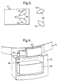
- FIG. 4 shows a further form of the base unit, this time in the form of an adapter for modifying an existing personal stereo apparatus to convert it into a cordless system.
- the adapter 62 comprises a lead terminating in a connector (e.g. a jack) 64 to fit the earphone socket 66 of a conventional personal stereo apparatus 68.
- the adapter thereby receives the audio output of the personal stereo.
- the adapter may be situated in a wall of a pouch or pocket 70 (shown partially cut-away) attached to a belt 72 to be worn by the user. At least part of the inwardly-facing surface of the belt is conductive, such that a terminal equivalent to terminal 24 of Figure 1 for transmitting signals into the user's body is formed.
- the personal stereo is placed in the pocket 70 and connected to the adapter 62.
- the audio output is processed as previously described in the context of Figures 1 and 2 and transmitted through the user's body to the earphones.
- the adapter 62 may be provided with storage cavities as in Figure 3, in which case power for the adapter is provided by an internal battery.
- the pouch or pocket 7 can equally be provided as part of a rucksack, handbag or shoulder bag, the handle or strap in each case containing the transmitting terminal.
- the pouch or pocket can be embodied in clothing or a fashion or sports accessory which is worn or carried.
- the base unit of the apparatus need only contain circuitry to convert the output signals of the conventional stereo apparatus to a form suitable for transmission through the housing terminal of the unit. It may be that the output signals from the conventional stereo apparatus are sufficient to power the unit without the need for a separate battery in the unit.
- the earphones could be provided in other forms, for example in any of the styles in which conventional earphones are provided.
- the earphones could be incorporated into the arms of a pair of spectacles. Instead of providing batteries for the earphones, they could be powered by solar cells.
- the earphones are connected to a structure, as in a conventional headset, on the frame of a pair of spectacles, a single array of solar cells could be mounted in a suitable position on the structure and connected by wiring to the earphones.
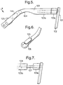
- Figures 5 to 9 show spectacles having lenses 101 located within a frame 102.
- An arm 103 extends from each side of the frame 102.
- the arm is preferably of the conventional shape and therefore has a curved portion 104 adapted to be placed behind the ear to allow the spectacles to be worn in a conventional manner, i.e. with the frame resting on the bridge of the wearer's nose and the ear end of the arm being located behind the wearer's ear.
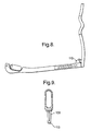
- Located at the ear end of the arm is an earphone 105 which is located in a recess 106 in the arm 104.
- the recess 106 may, in one alternative arrangement, be located on the outer surface of the ear end of the arm. In another alternative arrangement the earphone is located on a pin at the end of the arm.
- the arms may be attached to the frame by means of a hinge 110 such that the spectacles may be folded for storage in the conventional manner.
- the spectacles have adjusting means which enable the ear end of the arms of the spectacles to be moved from the conventional position in which the ear end, and thus the earphone, is located behind the ear to a listening position in which the ear end of the arm is located across the ear and the earphone is located in, or adjacent to, the ear.
- the arms of the spectacles may be formed such that they have some inherent elasticity to facilitate movement of the arms from the conventional position to the listening position.
- the adjusting means comprises means by which each of the arms is adjustable in length.
- one arrangement of the adjusting means is where the arm is divided into two portions, 103a and 103b.
- a pin 107 fixed to the front portion 103a is slidable in a bore 108 in the rear portion 103b.
- the pin and the co-operating bore are preferably curved upwardly such that when the arm is in the position shown in Figure 7, i.e.
- the recess 104 will sit comfortably behind the ear of the wearer and when the rear portion is moved forwardly along the pin such that portion 103b abuts portion 103a, the ear end of the arm is located across the ear and the earphone is located adjacent to, or in, the ear.
- the inclination of the rear portion changes.
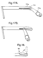
- the arms are configured such that as they move from the contracted position to the extended position the ear end of the arm transcribes an upwardly extending arc as illustrated in Figure 14.
- the movement from the contracted to the expanded position may be sprung loaded.
- a release catch 901 may extend from the arm, which when depressed releases the spring 902 which causes the arm to move to its extended configuration.
- the spring mechanism is illustrated in Figure 15 with reference to the arm arrangement of Figure 14. It will be understood that the spring loaded arrangement may be incorporated into other possible configurations for the arms.
- a projection may extend from the ear end of the arms such that movement of the arm from the extended to the contracted position could readily be achieved by the user holding the projection with, for example, the thumb and whilst holding the frame in his fingers moving the thumb towards the fingers.
- the arm is formed from two parts, a first part 103c and a second part 103d.
- the first and second parts are connected together by means of a pin 112 such that the second part is rotatable about the pin.
- the ear end of the arm may then be adjusted from a first position in which the first and second parts are collinear and in which the ear end of the arm sits comfortably behind the ear of the wearer, to a second position in which the second part is angled from the first part and in which the ear end of the arm is located across the ear and the earphone is located in, or adjacent to, the ear by pivoting the second part 103d about the pin 112.
- first part 171a and second part 171b are connected by a pin (not shown) extending from the second part which is slidable in a channel 172 in the first part.
- the channel is preferably curved upwardly at the end remote from the frame of the spectacles.
- the movement from the contracted position ( Figure 17B) to the extended position ( Figure 17A) is preferably sprung loaded.
- a release catch may be located in any convenient position.
- the earphone is to be located in the ear it is preferably pivotable from a position in which it is coplanar with the arm, for example extending from the end of the arm or located in a recess 106 ( Figure 6) to a position in which it is angled to the arm.
- the earphone is preferably angled at 90° to the arm.
- the earphone may be mounted on a pin 109 pivotable at a point 113 to the arm.
- the earphone is also rotatable about the axis of the pin, so that the spectacles may be worn in a variety of positions on the head with the earphones remaining in the correct orientation within the ear.
- the spectacles may be worn on the nose or on the head with the ear end of the arm located behind the ear or, they may be worn on the nose, on the head, behind the head or even under the chin with the earphones located in, or adjacent to, the ear.
- the arms of the spectacles are preferably curved in a convex manner to accommodate the wearer's head as illustrated in Figure 16. This enables the spectacles to be readily moved between the positions.
- the spectacles may be adapted such that the rotation of the earphone from the storage position in the manner described acts as a switch to activate the earphones.
- the earphone may be sprung loaded such that on release of a catch the earphones move to the listening position. Upon release of the catch the earphones preferably also rotate about the pin 109 to the vertical position.
- the action of moving the arm from the expanded to the contracted position may release the earpieces to the listening position.
- the spectacles additionally comprise one or two terminal(s) 114 arranged so that they can be positioned in use in contact with, or in close proximity to, the user's body so as to receive signals transmitted from the housing terminal through the user's body, and the or each earphone includes receiving circuitry arranged to receive the signals from the base unit.
- the terminal may therefore advantageously be located on the inner surface of the ear end of the arm. Where the spectacles include one terminal, the spectacles will include integral wires connecting the earphones to the terminal.
- the spectacles may be modified in a variety of ways.
- the spectacles may incorporate controls and/or switches to enable the user to control the volume level of the sound.
- Other parameters may also be controlled, such as the CD track or radio station selection.
- the or each earphone is arranged to transmit electrical control signals through the earphone terminal to be received by suitable circuitry in the base unit.
- Means may be incorporated between the arms of the spectacles and the earphones to reduce acoustic noise.
- the means are mounts formed from a resilient material such as rubber.
- the spectacles have been described with reference to their proposed use with portable audio apparatus such as a personal stereo. However, it will be appreciated that the spectacles would be advantageous in a variety of fields. For example, if a microphone is incorporated in the spectacles, for example, at the base of the lenses, the spectacles would be useful as part of a hands-free telephone, or as any type of communication device, such as may be used in television studios or in security operations.
- the spectacles illustrated are also suitable for use as a hearing aid device, particularly a directionally sensitive hearing aid device. Such a system would be particularly advantageous to a person who has difficulty with background noise.
- the lenses would include a liquid crystal or other means of achieving a darkening of the lens.
- This power could also be used to generate a head up display on the interior of the lenses which could operate in conjunction with the signal transmitted from the base unit.
- the lenses may include displays for games or other purposes.
- the electrical signals transmitted by the earphone may be derived from a microphone contained in or connected to the casing of the earphone and arranged to detect the user's speech.
- the apparatus may then be used as part of a telephone or other communication system, the base unit being connected by suitable means to a telephone network.
- the apparatus can be used to provide an improved hands-free mobile phone unit or car phone.
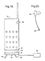
- Figures 19 and 20 illustrate a mobile telephone embodying the invention to provide a safe hands-free mode of operation for in-car use.
- the mobile telephone 72 is provided with a connector 74 on its bottom edge which is received by a complementary connector 75 in a storage device or base unit 76 which is mounted in the vehicle convenient to the driver.
- the base unit also contains an adapter 81 similar to the adapter 62 of Figure 4. This is connected to a terminal 82 in the driver's seat.
- the earphone and microphone circuits of the telephone 72 are connected via the connectors 74,75 to the base unit 76.
- the telephone is provided with a storage location 88 as in Figure 3 to house the earphone/microphone headset 84,86 when not in use and to recharge it.
- the mobile telephone of this embodiment has the advantage that background noise and feedback are reduced.
- the base unit 76 can be provided in the telephone 72 itself. Then the base unit 76 need be only a simple connector and furthermore the casing of the telephone 72 can be provided with an additional terminal similar to 24 of Figure 1 so that the headset 84,86 can be used with the telephone in the user's pocket, or merely carried rather than held to the head. Locating the headset in these positions overcomes any problems associated with locating a transmitter adjacent to the head.
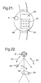
- a wristwatch provides a particularly convenient means of implementing the invention, because good contact can be achieved with the wearer's body via terminal on the inside of the strap or the back of the case.
- a wristwatch has a case 88 with a display 89, preferably an LCD display (normally showing the time), a keypad 90 on the front, and a body-contact terminal on the back.
- a removable earphone 91 similar to that of Figure 3 may be stowed in the body of the watch, together with a microphone 92.
- the wristwatch is configured as a mobile telephone or radio system, e.g. for use within a building, but equally or in addition, can embody a broadcast radio receiver or other small sized sound source.
- the batteries and the power-consuming circuits can be provided in a separate unit 94 as shown in Figure 22, only the controls being provided in the wristwatch. Then through-body communication is provided between all three parts of the system 88,91,94 by employing three or more carrier frequencies so that any two of the units can communicate without interference from the other, as illustrated diagrammatically by arrows 95, 96 and 97.
- the watch may have data input and/or storage facilities. Data may be readily transferred from the watch to a computer having as an integral part, or as an accessory, a terminal that enables contact to the body. Data can then be transferred without removing the watch from the wrist and without cables and connectors.
- the invention can also find application in other situations where conventional apparatus uses earphones or headphones connected by flexible leads to a base unit, or which use radio transmission between the base unit and the earphones, such as telephone switchboard systems, mobile speech recording and communication systems, television studio microphone and earphone communication units, conference systems, and aircraft and other transport entertainment or communication systems.
- the base unit may be for installation in a vehicle, means being provided to connect the base unit to the vehicle whereby part thereof in contact with or proximate the user's body forms said terminal.
- the steering wheel, the seats, or even the floor provide potentially suitable structures for use as the terminal.
Landscapes
- Physics & Mathematics (AREA)
- Engineering & Computer Science (AREA)
- Health & Medical Sciences (AREA)
- General Physics & Mathematics (AREA)
- Otolaryngology (AREA)
- Signal Processing (AREA)
- Computer Networks & Wireless Communication (AREA)
- Optics & Photonics (AREA)
- General Health & Medical Sciences (AREA)
- Ophthalmology & Optometry (AREA)
- Acoustics & Sound (AREA)
- Telephone Set Structure (AREA)
- Communication Control (AREA)
- Headphones And Earphones (AREA)
- Making Paper Articles (AREA)
- Near-Field Transmission Systems (AREA)
- Radio Transmission System (AREA)
- Details Of Audible-Bandwidth Transducers (AREA)
Claims (21)
- Schallerzeugungsverfahren, das die folgenden Schritte umfaßt:Bereitstellen einer Basiseinheit und einer Empfangseinheit, wobei die Basiseinheit einen Signalausgabeteil hat, der ausgeführt ist, um im Gebrauch mit der Oberfläche des Körpers eines Benutzers in Berührung oder in enger Nähe zu ihm zu sein, und wobei die Empfangseinheit wenigstens einen Ohrhörer aufweist,Anordnen des Signalausgabeteils in Berührung mit der Oberfläche des Körpers des Benutzers oder in enger Nähe zu ihm,an der Basiseinheit Anlegen eines mit einem Schallsignal modulierten Radiofrequenzsignals an den Signalausgabeteil zum Übertragen auf den Körper des Benutzers,Anordnen der Empfangseinheit mit einem Teil von ihr in Berührung mit dem Körper des Benutzers oder in enger Nähe zu ihm, um das Radiofrequenzsignal von der Basiseinheit nach dem Übertragen weitgehend ausschließlich durch den Körper des Benutzers zu empfangen,Demodulieren des empfangenen Signals, um ihm das Schallsignal zu entnehmen, undErzeugen von Schall, an das Ohr/die Ohren des Benutzers angrenzend, aus dem Schallsignal.
- Schallerzeugungsvorrichtung, die eine Basiseinheit (10; 62) und eine Empfangseinheit (30, 40) umfaßt, wobei die Basiseinheit (10; 62) einen Signalausgabeteil hat, der ausgeführt ist, um im Gebrauch mit der Oberfläche des Körpers eines Benutzers in Berührung oder in enger Nähe zu ihm zu sein, und wobei die Empfangseinheit (30, 40) wenigstens einen Ohrhörer aufweist,wobei die Basiseinheit des weiteren eine Einrichtung (14) zum Anlegen eines mit einem Schallsignal modulierten Radiofrequenzsignals an den Signalausgabeteil zum Übertragen weitgehend ausschließlich durch den Körper des Benutzers zur Empfangseinheit aufweist undwobei die Empfangseinheit (30, 40) des weiteren folgendes aufweist:eine Einrichtung (36), die zum Anordnen in Berührung mit dem Körper des Benutzers oder in enger Nähe zu ihm ausgeführt ist, um das Radiofrequenzsignal zu empfangen,eine an die Empfangseinrichtung angeschlossene Einrichtung zum Demodulieren des empfangenen Signals, um ihm das Schallsignal zu entnehmen, undeinen an die Demodulationseinrichtung angeschlossenen elektroakustischen Wandler zum Erzeugen von Schall aus dem Schallsignal.
- Schallerzeugungsvorrichtung nach Anspruch 2, bei der sich der Signalausgabeteil (24) an einem Gehäuse (12) der Basiseinheit befindet.
- Schallerzeugungsvorrichtung nach Anspruch 2, die einen linken und einen rechten Ohrhörer (30, 40) aufweist und bei der die Schaltung in der Basiseinheit (10) angeordnet ist, um linke und rechte Stereosignale geeignetermaßen verschlüsselt zum Empfang durch den linken und den rechten Ohrhörer zu übertragen.
- Schallerzeugungsvorrichtung nach Anspruch 2, 3 oder 4, bei der der oder jeder Ohrhörer (30, 40) eine Stromspeicher- oder stromerzeugende Vorrichtung zum Speisen der Ohrhörerschaltungsanordnung aufweist.
- Schallerzeugungsvorrichtung nach Anspruch 5, die einen zwischen der Stromspeicher- oder stromerzeugenden Vorrichtung und dem oder jedem Ohrhörer angeschlossenen Schalter aufweist und bei der der Schalter zur automatischen Betätigung durch Einsetzen des Ohrhörers in das Ohr des Benutzers angeordnet ist.
- Schallerzeugungsvorrichtung nach Anspruch 5 oder 6, die einen zwischen der Stromspeicher- oder stromerzeugenden Vorrichtung und dem oder jedem Ohrhörer angeschlossenen Schalter aufweist und bei der der Schalter angeordnet ist, so daß er in Reaktion auf die Detektion des Anliegens eines elektrischen Radiofrequenzsignals am Ohrhöreranschluß bei einer geeigneten Trägerfrequenz betätigt wird, mit der die Basiseinheit das mit einem Schallsignal modulierte Radiofrequenzsignal sendet.
- Schallerzeugungsvorrichtung nach Anspruch 5, 6 oder 7, bei der die Stromspeichervorrichtung eine Batterie oder einen Kondensator umfaßt.
- Schallerzeugungsvorrichtung nach Anspruch 5, 6 oder 7, bei der die Stromspeichervorrichtung eine Solarzelle umfaßt.
- Schallerzeugungsvorrichtung nach Anspruch 8 oder 9, bei der die Basiseinheit (10) eine Einrichtung (54, 56) zum Wiederaufladen der Stromspeichervorrichtung hat.
- Schallerzeugungsvorrichtung nach Anspruch 10, bei der die Basiseinheit (10) eine Einrichtung (50) zum Verstauen von dem oder jedem Ohrhörer (30, 40), wenn nicht in Gebrauch, hat und bei der die Einrichtung zum Verstauen elektrische Verbinder (54, 56) zum Anschließen der Stromspeichervorrichtung an die Aufladeeinrichtung aufweist.
- Schallerzeugungsvorrichtung nach einem der Ansprüche 4 bis 11, bei der der oder jeder Ohrhörer (30, 40) eine Hülle aus elektrisch leitendem Material hat, der auch als Ohrhöreranschluß wirkt.
- Schallerzeugungsvorrichtung nach einem der Ansprüche 2 bis 12, bei der die Empfangseinheit (30, 40) einen Schalter zum Ausschalten der Empfangseinheitsschaltung oder zum Umschalten dieser in einen Ruhezustand, wenn die Empfangseinheit nicht in Gebrauch ist.
- Schallerzeugungsvorrichtung nach einem der Ansprüche 2 bis 13, bei der die Basiseinheit (10) mit einer Klammer (20) zum lösbaren Anbringen an der Kleidung des Benutzers versehen ist und der Signalausgabeteil (24) an der Klammer befestigt ist oder von der Klammer gebildet wird.
- Schallerzeugungsvorrichtung nach einem der Ansprüche 2 bis 14, bei der die Basiseinheit (62) zum Anbringen an einem existierenden tragbaren Stereogerät (68) oder einer anderen Vorrichtung, die eine Signalquelle ist, ausgeführt ist, wobei die Schaltung der Basiseinheit zum Empfangen von Signalen von der Schaltung der Signalquellenvorrichtung ausgeführt ist.
- Schallerzeugungsvorrichtung nach einem der Ansprüche 2 bis 14, bei der die Basiseinheit (76) zur Installation in einem Fahrzeug ausgeführt ist und Einrichtungen zum Anschließen der Basiseinheit an das Fahrzeug bereitgestellt sind, wodurch ein Teil (82) davon, der mit dem Körper des Benutzers in Berührung oder in enger Nähe zu ihm ist, den Signalausgabeteil bildet.
- Schallerzeugungsvorrichtung nach einem der Ansprüche 2 bis 16, bei der die Basiseinheit ein Kassettengerät und/oder einen CD-Spieler und/oder einen Radioempfänger aufweist.
- Schallerzeugungsvorrichtung nach einem der Ansprüche 2 bis 16, bei der die Basiseinheit ein Mobilfunktelefon (88) ist.
- Schallerzeugungsvorrichtung nach einem der Ansprüche 2 bis 18, bei der die Empfangseinheit (84) eine Einrichtung zum Übertragen von Signalen weitgehend ausschließlich durch den Körper des Benutzers zur Basiseinheit (74) aufweist.
- Schallerzeugungsvorrichtung nach Anspruch 19, bei der die Empfangseinheit (84) mit einem Mikrofon (86) zum Übertragen von Schallsignalen weitgehend ausschließlich durch den Körper des Benutzers zur Basiseinheit (76) versehen ist.
- Schallerzeugungsvorrichtung nach Anspruch 19, bei der die Empfangseinheit zum Übertragen von Steuersignalen weitgehend ausschließlich durch den Körper des Benutzers zur Basiseinheit ausgeführt ist.
Applications Claiming Priority (7)
| Application Number | Priority Date | Filing Date | Title |
|---|---|---|---|
| GBGB9501408.0A GB9501408D0 (en) | 1995-01-25 | 1995-01-25 | Audio apparatus |
| GB9501408 | 1995-01-25 | ||
| GBGB9506448.1A GB9506448D0 (en) | 1995-03-29 | 1995-03-29 | Spectacles |
| GB9506448 | 1995-03-29 | ||
| GB9522535 | 1995-11-03 | ||
| GBGB9522535.5A GB9522535D0 (en) | 1995-01-25 | 1995-11-03 | Communication method |
| PCT/GB1996/000167 WO1996023373A1 (en) | 1995-01-25 | 1996-01-25 | Communication method |
Publications (2)
| Publication Number | Publication Date |
|---|---|
| EP0806099A1 EP0806099A1 (de) | 1997-11-12 |
| EP0806099B1 true EP0806099B1 (de) | 2000-08-30 |
Family
ID=27267556
Family Applications (1)
| Application Number | Title | Priority Date | Filing Date |
|---|---|---|---|
| EP96901050A Revoked EP0806099B1 (de) | 1995-01-25 | 1996-01-25 | Kommunikationsverfahren |
Country Status (9)
| Country | Link |
|---|---|
| US (1) | US6118882A (de) |
| EP (1) | EP0806099B1 (de) |
| JP (1) | JPH10513021A (de) |
| AT (1) | ATE196044T1 (de) |
| AU (1) | AU712988B2 (de) |
| CA (1) | CA2216416A1 (de) |
| DE (1) | DE69610075T2 (de) |
| ES (1) | ES2152008T3 (de) |
| WO (1) | WO1996023373A1 (de) |
Cited By (4)
| Publication number | Priority date | Publication date | Assignee | Title |
|---|---|---|---|---|
| FR2869120A1 (fr) * | 2004-04-15 | 2005-10-21 | World Wide Watch | Montre interactive. |
| WO2011006063A1 (en) * | 2009-07-10 | 2011-01-13 | Atlantic Signal, Llc | Bone conduction communications headset with hearing protection |
| USD676027S1 (en) | 2012-01-17 | 2013-02-12 | Atlantic Signal, Llc | Housing for bone vibrating transducer for communications headset |
| US9107004B2 (en) | 2009-07-10 | 2015-08-11 | Atlantic Signal, Llc | Bone conduction communications headset with hearing protection |
Families Citing this family (106)
| Publication number | Priority date | Publication date | Assignee | Title |
|---|---|---|---|---|
| US6978159B2 (en) | 1996-06-19 | 2005-12-20 | Board Of Trustees Of The University Of Illinois | Binaural signal processing using multiple acoustic sensors and digital filtering |
| US6987856B1 (en) | 1996-06-19 | 2006-01-17 | Board Of Trustees Of The University Of Illinois | Binaural signal processing techniques |
| FI111674B (fi) | 1996-10-31 | 2003-08-29 | Nokia Corp | Käyttäjäliityntä |
| US7787647B2 (en) | 1997-01-13 | 2010-08-31 | Micro Ear Technology, Inc. | Portable system for programming hearing aids |
| DE19712412A1 (de) * | 1997-03-25 | 1998-10-01 | Deutsche Telekom Ag | Mobilfunktelefon |
| IT1298975B1 (it) * | 1998-03-31 | 2000-02-07 | Egidio Renna | Montatura di occhiali con astine auricolari |
| FR2781894B1 (fr) * | 1998-07-31 | 2001-10-19 | Ecurie Partners | Adaptation d'un dispositif electronique sur/dans une montre |
| US6430110B2 (en) | 1998-07-31 | 2002-08-06 | Jean-Michel Baroche | Multifunction wristwatch with electronic device |
| US6519448B1 (en) * | 1998-09-30 | 2003-02-11 | William A. Dress | Personal, self-programming, short-range transceiver system |
| EP1049310A1 (de) * | 1999-04-28 | 2000-11-02 | Andrea De Pol | Zusatzeinrichtung für den Freisprechbetrieb eines Mobiltelefons |
| JP2001144662A (ja) * | 1999-11-11 | 2001-05-25 | Sony Corp | 携帯型オーディオ・リスニング装置 |
| DK1252799T3 (da) | 2000-01-20 | 2012-01-23 | Starkey Lab Inc | Fremgangsmåde og apparat til tilpasning af høreapparater |
| US6754472B1 (en) * | 2000-04-27 | 2004-06-22 | Microsoft Corporation | Method and apparatus for transmitting power and data using the human body |
| CA2407855C (en) * | 2000-05-10 | 2010-02-02 | The Board Of Trustees Of The University Of Illinois | Interference suppression techniques |
| US7206423B1 (en) | 2000-05-10 | 2007-04-17 | Board Of Trustees Of University Of Illinois | Intrabody communication for a hearing aid |
| US6625476B1 (en) * | 2000-06-01 | 2003-09-23 | Nokia Corporation | User interface apparatus, and associated method, for facilitating hands-free operation of a radio device |
| US8482488B2 (en) | 2004-12-22 | 2013-07-09 | Oakley, Inc. | Data input management system for wearable electronically enabled interface |
| US20120105740A1 (en) | 2000-06-02 | 2012-05-03 | Oakley, Inc. | Eyewear with detachable adjustable electronics module |
| JP2002149317A (ja) * | 2000-11-14 | 2002-05-24 | Nagano Fujitsu Component Kk | 入力システム及び入力装置 |
| US8452259B2 (en) | 2001-02-20 | 2013-05-28 | Adidas Ag | Modular personal network systems and methods |
| KR200232603Y1 (ko) * | 2001-02-20 | 2001-09-28 | 김서영 | 충전이 가능한 휴대폰 홀더 |
| AU2002255568B8 (en) | 2001-02-20 | 2014-01-09 | Adidas Ag | Modular personal network systems and methods |
| JP2004530310A (ja) * | 2001-03-13 | 2004-09-30 | フォーナック アーゲー | 着脱可能な機械的及び/又は電気的結合の形成方法、この方法を使用する聴音装置及び聴音装置システム |
| US7254246B2 (en) * | 2001-03-13 | 2007-08-07 | Phonak Ag | Method for establishing a binaural communication link and binaural hearing devices |
| US6769767B2 (en) * | 2001-04-30 | 2004-08-03 | Qr Spex, Inc. | Eyewear with exchangeable temples housing a transceiver forming ad hoc networks with other devices |
| US7013009B2 (en) | 2001-06-21 | 2006-03-14 | Oakley, Inc. | Eyeglasses with wireless communication features |
| USD460953S1 (en) | 2001-09-29 | 2002-07-30 | Tyler B. Argle | Cellular phone |
| US20030142841A1 (en) * | 2002-01-30 | 2003-07-31 | Sensimetrics Corporation | Optical signal transmission between a hearing protector muff and an ear-plug receiver |
| US6643503B1 (en) | 2002-04-17 | 2003-11-04 | Motorola, Inc. | Wireless speaker for radio communication device |
| DE50313583D1 (de) * | 2002-06-04 | 2011-05-12 | Adec & Partner Ag | Kopfhörer |
| CA2494661A1 (en) | 2002-07-26 | 2004-02-05 | Oakley, Inc. | Wireless interactive headset |
| US20040086141A1 (en) * | 2002-08-26 | 2004-05-06 | Robinson Arthur E. | Wearable buddy audio system |
| US7512448B2 (en) * | 2003-01-10 | 2009-03-31 | Phonak Ag | Electrode placement for wireless intrabody communication between components of a hearing system |
| US7096048B2 (en) * | 2003-04-01 | 2006-08-22 | Sanders Donald T | Portable communications device |
| US7945064B2 (en) * | 2003-04-09 | 2011-05-17 | Board Of Trustees Of The University Of Illinois | Intrabody communication with ultrasound |
| US7076072B2 (en) * | 2003-04-09 | 2006-07-11 | Board Of Trustees For The University Of Illinois | Systems and methods for interference-suppression with directional sensing patterns |
| US7117010B2 (en) * | 2003-05-29 | 2006-10-03 | Cingular Wireless Ii, Llc | Wireless phone powered inductive loopset |
| US7684754B2 (en) * | 2003-06-03 | 2010-03-23 | Microsoft Corporation | Capacitive bonding of devices |
| US7426279B2 (en) * | 2003-06-11 | 2008-09-16 | Cochran James L | Electromagnetic audio and data signaling transducers and systems |
| US6989744B2 (en) * | 2003-06-13 | 2006-01-24 | Proebsting James R | Infant monitoring system with removable ear insert |
| DE20311431U1 (de) * | 2003-07-24 | 2003-10-02 | Degwitz-van Son, Udo, 50679 Köln | Tragevorrichtung |
| US7822983B2 (en) * | 2003-08-21 | 2010-10-26 | Microsoft Corporation | Physical device bonding |
| US20050091060A1 (en) * | 2003-10-23 | 2005-04-28 | Wing Thomas W. | Hearing aid for increasing voice recognition through voice frequency downshift and/or voice substitution |
| EP1598691A1 (de) * | 2004-05-17 | 2005-11-23 | Inspecs Ltd. | Brillenfassung mit Multimediaeinrichtung und Multimediaeinrichtung zur Montage an einer Brillenfassung |
| GB2437682B (en) * | 2005-01-31 | 2009-02-25 | Jow Tong Technology Co Ltd | Eyeglasses with signal receiving function |
| US7577459B2 (en) * | 2005-05-11 | 2009-08-18 | Nokia Corporation | Establishing a communication link |
| FI20055590L (fi) * | 2005-11-03 | 2007-05-04 | Wearfone Oy | Menetelmä ja laite äänen muodostamiseksi langattomasti käyttäjän korvaan |
| KR101128170B1 (ko) * | 2006-05-10 | 2012-03-23 | 엘지전자 주식회사 | 음향 트랜스듀서를 갖는 휴대 단말기 및 그 제어방법 |
| US7801319B2 (en) | 2006-05-30 | 2010-09-21 | Sonitus Medical, Inc. | Methods and apparatus for processing audio signals |
| US8291912B2 (en) | 2006-08-22 | 2012-10-23 | Sonitus Medical, Inc. | Systems for manufacturing oral-based hearing aid appliances |
| CA2601662A1 (en) | 2006-09-18 | 2008-03-18 | Matthias Mullenborn | Wireless interface for programming hearing assistance devices |
| JP4622991B2 (ja) * | 2006-11-15 | 2011-02-02 | 株式会社デンソー | カーオーディオシステムの音量制御装置 |
| US8265326B2 (en) * | 2007-03-14 | 2012-09-11 | Sanjeev Kumar Singh | Hand-held, portable electronic device with retainer port for receiving one or more attachable wireless audiophones for in situ charging |
| US8155367B2 (en) * | 2006-11-27 | 2012-04-10 | Sanjeev Kumar Singh | Hand-held, portable electronic device with a retainer port for removably coupling an attachable wireless audiophone thereto |
| WO2008076774A2 (en) | 2006-12-14 | 2008-06-26 | Oakley, Inc. | Wearable high resolution audio visual interface |
| FR2915815A1 (fr) * | 2007-05-03 | 2008-11-07 | Richard Chene | Dispositif comportant un equipement electrique, tel que branche de lunettes ou oreillette, a mise hors service automatique |
| US8270638B2 (en) | 2007-05-29 | 2012-09-18 | Sonitus Medical, Inc. | Systems and methods to provide communication, positioning and monitoring of user status |
| NO328038B1 (no) | 2007-06-01 | 2009-11-16 | Freebit As | Forbedret oreenhet |
| US20090060231A1 (en) * | 2007-07-06 | 2009-03-05 | Thomas William Buroojy | Bone Conduction Headphones |
| US20090046869A1 (en) * | 2007-08-16 | 2009-02-19 | Griffin Jr Paul P | Wireless audio receivers |
| US8433080B2 (en) | 2007-08-22 | 2013-04-30 | Sonitus Medical, Inc. | Bone conduction hearing device with open-ear microphone |
| US8224013B2 (en) | 2007-08-27 | 2012-07-17 | Sonitus Medical, Inc. | Headset systems and methods |
| US20090074214A1 (en) * | 2007-09-13 | 2009-03-19 | Bionica Corporation | Assistive listening system with plug in enhancement platform and communication port to download user preferred processing algorithms |
| US20090074216A1 (en) * | 2007-09-13 | 2009-03-19 | Bionica Corporation | Assistive listening system with programmable hearing aid and wireless handheld programmable digital signal processing device |
| US20090076816A1 (en) * | 2007-09-13 | 2009-03-19 | Bionica Corporation | Assistive listening system with display and selective visual indicators for sound sources |
| US20090074206A1 (en) * | 2007-09-13 | 2009-03-19 | Bionica Corporation | Method of enhancing sound for hearing impaired individuals |
| US20090076825A1 (en) * | 2007-09-13 | 2009-03-19 | Bionica Corporation | Method of enhancing sound for hearing impaired individuals |
| US20090074203A1 (en) * | 2007-09-13 | 2009-03-19 | Bionica Corporation | Method of enhancing sound for hearing impaired individuals |
| US20090076804A1 (en) * | 2007-09-13 | 2009-03-19 | Bionica Corporation | Assistive listening system with memory buffer for instant replay and speech to text conversion |
| US20090076636A1 (en) * | 2007-09-13 | 2009-03-19 | Bionica Corporation | Method of enhancing sound for hearing impaired individuals |
| US7682303B2 (en) | 2007-10-02 | 2010-03-23 | Sonitus Medical, Inc. | Methods and apparatus for transmitting vibrations |
| KR101383258B1 (ko) * | 2007-11-08 | 2014-04-08 | 삼성전자주식회사 | 이동통신 시스템에서 인체 통신 기능을 제공하기 위한 장치및 방법 |
| US8795172B2 (en) | 2007-12-07 | 2014-08-05 | Sonitus Medical, Inc. | Systems and methods to provide two-way communications |
| JP2009152666A (ja) * | 2007-12-18 | 2009-07-09 | Toshiba Corp | 音響出力制御装置、音響再生装置および音響出力制御方法 |
| US7974845B2 (en) | 2008-02-15 | 2011-07-05 | Sonitus Medical, Inc. | Stuttering treatment methods and apparatus |
| US8270637B2 (en) | 2008-02-15 | 2012-09-18 | Sonitus Medical, Inc. | Headset systems and methods |
| US8023676B2 (en) | 2008-03-03 | 2011-09-20 | Sonitus Medical, Inc. | Systems and methods to provide communication and monitoring of user status |
| US20090226020A1 (en) | 2008-03-04 | 2009-09-10 | Sonitus Medical, Inc. | Dental bone conduction hearing appliance |
| US8150075B2 (en) | 2008-03-04 | 2012-04-03 | Sonitus Medical, Inc. | Dental bone conduction hearing appliance |
| JPWO2009116272A1 (ja) * | 2008-03-17 | 2011-07-21 | 株式会社テムコジャパン | 骨伝導スピーカ及びそれを用いた聴取装置 |
| US20090245549A1 (en) * | 2008-03-26 | 2009-10-01 | Microsoft Corporation | Identification of earbuds used with personal media players |
| US20100020982A1 (en) * | 2008-07-28 | 2010-01-28 | Plantronics, Inc. | Donned/doffed multimedia file playback control |
| JP5211964B2 (ja) * | 2008-09-16 | 2013-06-12 | ブラザー工業株式会社 | 頭部装着型画像表示装置 |
| DE102009016661B4 (de) * | 2009-04-07 | 2015-05-07 | Siemens Medical Instruments Pte. Ltd. | Hörgeräteanordnung mit einem Tragehalsband mit integrierter Antenne und zugehöriges Verfahren zur drahtlosen Übertragung von Daten |
| WO2011041078A1 (en) | 2009-10-02 | 2011-04-07 | Sonitus Medical, Inc. | Intraoral appliance for sound transmission via bone conduction |
| JP5471294B2 (ja) * | 2009-10-23 | 2014-04-16 | 株式会社デンソー | 人体通信用の通信装置 |
| CA2740296C (en) * | 2010-01-06 | 2018-05-01 | Skullcandy, Inc. | Dj mixing headphones |
| US8462968B2 (en) * | 2010-06-18 | 2013-06-11 | Research In Motion Limited | Shared coil for inductive charging and hearing-aid-compliance requirements in mobile phones |
| US8867748B2 (en) | 2010-12-21 | 2014-10-21 | John G. Posa | Wireless personal listening system and method |
| CA2825413A1 (en) * | 2011-01-07 | 2012-07-12 | Widex A/S | A hearing aid system and a hearing aid |
| CN108873372B (zh) | 2018-08-24 | 2024-06-14 | 深圳市韶音科技有限公司 | 一种铰链及眼镜 |
| CN204331191U (zh) | 2012-02-17 | 2015-05-13 | 奥克利有限公司 | 眼镜和双重附接构件 |
| CN103926712B (zh) * | 2013-01-10 | 2016-05-11 | 荆延杰 | 具有通话功能的眼镜 |
| US9319778B2 (en) | 2013-03-13 | 2016-04-19 | Google Inc. | Communicating via a body-area network |
| WO2014149631A2 (en) | 2013-03-15 | 2014-09-25 | Oakley, Inc. | Electronic ornamentation for eyewear |
| CN205691887U (zh) | 2013-06-12 | 2016-11-16 | 奥克利有限公司 | 模块化通信系统和眼镜通信系统 |
| US11582565B2 (en) | 2014-01-06 | 2023-02-14 | Shenzhen Shokz Co., Ltd. | Systems and methods for suppressing sound leakage |
| US11558698B2 (en) | 2014-01-06 | 2023-01-17 | Shenzhen Shokz Co., Ltd. | Systems and methods for suppressing sound leakage |
| US9485563B2 (en) | 2014-08-14 | 2016-11-01 | Firas Chaabani | Two way communication assembly |
| IT201700062337A1 (it) | 2017-06-07 | 2018-12-07 | Safilo Sa Fabbrica Italiana Lavorazione Occhiali Spa | Occhiali con dispositivi auricolari |
| US10716511B2 (en) | 2018-07-31 | 2020-07-21 | Manicka Institute Llc | Subcutaneous device for monitoring and/or providing therapies |
| US10576291B2 (en) | 2018-07-31 | 2020-03-03 | Manicka Institute Llc | Subcutaneous device |
| KR102528290B1 (ko) | 2018-08-24 | 2023-05-03 | 썬전 샥 컴퍼니 리미티드 | 안경 |
| US11604367B2 (en) | 2020-04-08 | 2023-03-14 | Facense Ltd. | Smartglasses with bendable temples |
| US20220160253A1 (en) * | 2020-11-25 | 2022-05-26 | Calyan Technologies, Inc. | Antennas for a subcutaneous device |
| US12502531B2 (en) | 2021-04-26 | 2025-12-23 | Manicka Institute Llc | Subcutaneous device for preventing and treating atherosclerosis |
Family Cites Families (34)
| Publication number | Priority date | Publication date | Assignee | Title |
|---|---|---|---|---|
| GB743722A (en) * | 1953-03-07 | 1956-01-25 | George William Patch | Improvements in or relating to hearing aid accessories |
| GB1089238A (en) * | 1965-03-10 | 1967-11-01 | Non Slip Temple Company Inc | Improvements in eyeglass frames |
| GB1183487A (en) * | 1966-06-06 | 1970-03-04 | Akg Akustische Kino Geraete | Listening Spectacles |
| FR1563892A (de) * | 1967-02-13 | 1969-04-18 | ||
| US3629521A (en) * | 1970-01-08 | 1971-12-21 | Intelectron Corp | Hearing systems |
| US4067342A (en) * | 1976-04-06 | 1978-01-10 | Medtronic, Inc. | Tape electrode |
| DE2907570A1 (de) * | 1979-02-27 | 1980-08-28 | Asko Olavi Pietarila | Verfahren zum kontinuierlichen messen der herzschlagfrequenz |
| GB2043257B (en) * | 1979-02-27 | 1983-08-17 | Pietarila A O | Using the body as a signal conductor in ecg measurement |
| JPS5850078B2 (ja) * | 1979-05-04 | 1983-11-08 | 株式会社 弦エンジニアリング | 振動ピックアップ型イヤ−マイクロホンの送信装置および送受信装置 |
| DE2938584A1 (de) * | 1979-09-24 | 1981-04-09 | Battelle-Institut E.V., 6000 Frankfurt | Verfahren zur auffindung von verschuetteten |
| JPS5744276A (en) * | 1980-08-29 | 1982-03-12 | Matsushita Electric Ind Co Ltd | Necklace type tape reproducer |
| JPS57160436A (en) * | 1981-03-27 | 1982-10-02 | Gen Engineering Kk | Communication apparatus |
| US4440160A (en) * | 1982-01-19 | 1984-04-03 | The Johns Hopkins University | Self-injurious behavior inhibiting system |
| GB2129176B (en) * | 1982-10-12 | 1986-03-19 | Roundel Electronics | Indentification system |
| JPS60250731A (ja) * | 1984-05-25 | 1985-12-11 | Matsushita Electric Works Ltd | 生体通信方式 |
| JPS6146638A (ja) * | 1984-08-11 | 1986-03-06 | Matsushita Electric Works Ltd | 情報伝送装置 |
| JPS6146639A (ja) * | 1984-08-11 | 1986-03-06 | Matsushita Electric Works Ltd | 情報伝送装置 |
| DE8617136U1 (de) * | 1986-06-25 | 1986-08-21 | Weidemann, Hans-Dieter, 1000 Berlin | Hörbrille |
| US4901355A (en) * | 1986-08-04 | 1990-02-13 | Moore Michael R | Combination multiple supported variable position audio intake control devices |
| GB8713795D0 (en) * | 1987-06-12 | 1987-07-15 | Roberts M | Earphone headsets |
| US4845751A (en) * | 1988-03-16 | 1989-07-04 | Schwab Brian H | Wireless stereo headphone |
| DE8816422U1 (de) * | 1988-05-06 | 1989-08-10 | Siemens AG, 1000 Berlin und 8000 München | Hörhilfegerät mit drahtloser Fernsteuerung |
| DE3831809A1 (de) * | 1988-09-19 | 1990-03-22 | Funke Hermann | Zur mindestens teilweisen implantation im lebenden koerper bestimmtes geraet |
| JP2870791B2 (ja) * | 1989-03-20 | 1999-03-17 | ソニー株式会社 | ワイヤレスヘッドホン |
| JPH0419890A (ja) * | 1990-05-11 | 1992-01-23 | Sony Corp | 無線伝送式の音声信号再生装置 |
| JPH0634543B2 (ja) * | 1990-06-05 | 1994-05-02 | ソニー株式会社 | オーディオ信号の再生装置 |
| EP0491072B1 (de) * | 1990-12-18 | 1995-05-24 | Siemens Aktiengesellschaft | Hörgerät |
| US5279607A (en) * | 1991-05-30 | 1994-01-18 | The State University Of New York | Telemetry capsule and process |
| WO1996013136A1 (en) * | 1992-02-14 | 1996-05-02 | Da Silva Jean Pierre M | Audio-adapted eyeglass retainer |
| DE4223515C1 (de) * | 1992-07-17 | 1994-02-24 | Burkhard Ballein | Brille mit einer Gläserfassung |
| JP3255995B2 (ja) * | 1992-10-23 | 2002-02-12 | 株式会社日立製作所 | テレビ電話装置 |
| FR2701616B3 (fr) * | 1993-02-10 | 1995-05-05 | Crde | Système électronique de transmission à radiofréquence. |
| JPH07143214A (ja) * | 1993-11-19 | 1995-06-02 | Sony Corp | 携帯用電話機 |
| US5815579A (en) * | 1995-03-08 | 1998-09-29 | Interval Research Corporation | Portable speakers with phased arrays |
-
1996
- 1996-01-25 CA CA002216416A patent/CA2216416A1/en not_active Abandoned
- 1996-01-25 AT AT96901050T patent/ATE196044T1/de not_active IP Right Cessation
- 1996-01-25 WO PCT/GB1996/000167 patent/WO1996023373A1/en not_active Ceased
- 1996-01-25 ES ES96901050T patent/ES2152008T3/es not_active Expired - Lifetime
- 1996-01-25 JP JP8522732A patent/JPH10513021A/ja active Pending
- 1996-01-25 EP EP96901050A patent/EP0806099B1/de not_active Revoked
- 1996-01-25 US US08/913,046 patent/US6118882A/en not_active Expired - Fee Related
- 1996-01-25 AU AU44927/96A patent/AU712988B2/en not_active Ceased
- 1996-01-25 DE DE69610075T patent/DE69610075T2/de not_active Expired - Fee Related
Cited By (6)
| Publication number | Priority date | Publication date | Assignee | Title |
|---|---|---|---|---|
| FR2869120A1 (fr) * | 2004-04-15 | 2005-10-21 | World Wide Watch | Montre interactive. |
| WO2005103846A3 (fr) * | 2004-04-15 | 2006-05-04 | World Wide Watch Sarl | Montre interactive |
| WO2011006063A1 (en) * | 2009-07-10 | 2011-01-13 | Atlantic Signal, Llc | Bone conduction communications headset with hearing protection |
| US8385576B2 (en) | 2009-07-10 | 2013-02-26 | Atlantic Signal, Llc | Bone conduction communications headset with hearing protection |
| US9107004B2 (en) | 2009-07-10 | 2015-08-11 | Atlantic Signal, Llc | Bone conduction communications headset with hearing protection |
| USD676027S1 (en) | 2012-01-17 | 2013-02-12 | Atlantic Signal, Llc | Housing for bone vibrating transducer for communications headset |
Also Published As
| Publication number | Publication date |
|---|---|
| ES2152008T3 (es) | 2001-01-16 |
| US6118882A (en) | 2000-09-12 |
| CA2216416A1 (en) | 1996-08-01 |
| JPH10513021A (ja) | 1998-12-08 |
| DE69610075T2 (de) | 2001-04-12 |
| AU4492796A (en) | 1996-08-14 |
| EP0806099A1 (de) | 1997-11-12 |
| DE69610075D1 (de) | 2000-10-05 |
| WO1996023373A1 (en) | 1996-08-01 |
| AU712988B2 (en) | 1999-11-18 |
| ATE196044T1 (de) | 2000-09-15 |
Similar Documents
| Publication | Publication Date | Title |
|---|---|---|
| EP0806099B1 (de) | Kommunikationsverfahren | |
| US5881149A (en) | Portable communications device with wireless transmitter and detachable earpiece including a wireless receiver | |
| US8094858B2 (en) | Eyewear retention device | |
| US6091832A (en) | Wearable personal audio loop apparatus | |
| US7988283B2 (en) | Eyeglasses with detachable adjustable electronics module | |
| US7565187B1 (en) | Transceiver device and fastener | |
| US7096048B2 (en) | Portable communications device | |
| US6546264B1 (en) | Helmet headphones | |
| US20060158608A1 (en) | Eyeglasses with signal receiving function | |
| US20080153556A1 (en) | Wireless Ear-Phone and Portable Terminal Using the Same | |
| US20060177086A1 (en) | Tubular, flexible wireless communication device | |
| US20140233754A1 (en) | Headphone system with retractable microphone | |
| JP2002516553A (ja) | 頭部装着型の娯楽及び/又は通信装置 | |
| JP2000504889A (ja) | クリップと一体となった電子通信装置 | |
| US7630772B1 (en) | Methods of converting a behind-the-ear speech processor unit into a body worn speech processor unit | |
| WO2006113042A1 (en) | Speakerphone with detachable ear bud | |
| JP3140230U (ja) | 受信機能付きメガネ | |
| KR200189084Y1 (ko) | 무선 이어마이크폰 | |
| EP1223682B1 (de) | Elektronisches Gerät für eine mobile Radiostation | |
| CN216086976U (zh) | 一种具有无线通讯功能的耳机盒及无线通讯设备 | |
| JPH10313494A (ja) | イヤホン | |
| CN216086975U (zh) | 一种耳机盒及组合设备 | |
| CN216086980U (zh) | 一种具有无线通讯功能的耳机盒及无线通讯设备 | |
| CN222602552U (zh) | 一种带噪声显示的蓝牙头戴式防护耳机 | |
| KR200184608Y1 (ko) | 휴대전화용 핸드프리 장치 |
Legal Events
| Date | Code | Title | Description |
|---|---|---|---|
| PUAI | Public reference made under article 153(3) epc to a published international application that has entered the european phase |
Free format text: ORIGINAL CODE: 0009012 |
|
| 17P | Request for examination filed |
Effective date: 19970819 |
|
| AK | Designated contracting states |
Kind code of ref document: A1 Designated state(s): AT BE CH DE DK ES FR GB GR IE IT LI LU MC NL PT SE |
|
| 17Q | First examination report despatched |
Effective date: 19971128 |
|
| GRAG | Despatch of communication of intention to grant |
Free format text: ORIGINAL CODE: EPIDOS AGRA |
|
| GRAG | Despatch of communication of intention to grant |
Free format text: ORIGINAL CODE: EPIDOS AGRA |
|
| GRAG | Despatch of communication of intention to grant |
Free format text: ORIGINAL CODE: EPIDOS AGRA |
|
| GRAH | Despatch of communication of intention to grant a patent |
Free format text: ORIGINAL CODE: EPIDOS IGRA |
|
| GRAH | Despatch of communication of intention to grant a patent |
Free format text: ORIGINAL CODE: EPIDOS IGRA |
|
| GRAA | (expected) grant |
Free format text: ORIGINAL CODE: 0009210 |
|
| AK | Designated contracting states |
Kind code of ref document: B1 Designated state(s): AT BE CH DE DK ES FR GB GR IE IT LI LU MC NL PT SE |
|
| PG25 | Lapsed in a contracting state [announced via postgrant information from national office to epo] |
Ref country code: NL Free format text: LAPSE BECAUSE OF FAILURE TO SUBMIT A TRANSLATION OF THE DESCRIPTION OR TO PAY THE FEE WITHIN THE PRESCRIBED TIME-LIMIT Effective date: 20000830 Ref country code: BE Free format text: LAPSE BECAUSE OF FAILURE TO SUBMIT A TRANSLATION OF THE DESCRIPTION OR TO PAY THE FEE WITHIN THE PRESCRIBED TIME-LIMIT Effective date: 20000830 Ref country code: AT Free format text: LAPSE BECAUSE OF FAILURE TO SUBMIT A TRANSLATION OF THE DESCRIPTION OR TO PAY THE FEE WITHIN THE PRESCRIBED TIME-LIMIT Effective date: 20000830 |
|
| REF | Corresponds to: |
Ref document number: 196044 Country of ref document: AT Date of ref document: 20000915 Kind code of ref document: T |
|
| REG | Reference to a national code |
Ref country code: CH Ref legal event code: EP |
|
| REG | Reference to a national code |
Ref country code: IE Ref legal event code: FG4D |
|
| REF | Corresponds to: |
Ref document number: 69610075 Country of ref document: DE Date of ref document: 20001005 |
|
| ITF | It: translation for a ep patent filed | ||
| PG25 | Lapsed in a contracting state [announced via postgrant information from national office to epo] |
Ref country code: SE Free format text: LAPSE BECAUSE OF FAILURE TO SUBMIT A TRANSLATION OF THE DESCRIPTION OR TO PAY THE FEE WITHIN THE PRESCRIBED TIME-LIMIT Effective date: 20001130 Ref country code: PT Free format text: LAPSE BECAUSE OF FAILURE TO SUBMIT A TRANSLATION OF THE DESCRIPTION OR TO PAY THE FEE WITHIN THE PRESCRIBED TIME-LIMIT Effective date: 20001130 Ref country code: DK Free format text: LAPSE BECAUSE OF FAILURE TO SUBMIT A TRANSLATION OF THE DESCRIPTION OR TO PAY THE FEE WITHIN THE PRESCRIBED TIME-LIMIT Effective date: 20001130 |
|
| PG25 | Lapsed in a contracting state [announced via postgrant information from national office to epo] |
Ref country code: GR Free format text: LAPSE BECAUSE OF FAILURE TO SUBMIT A TRANSLATION OF THE DESCRIPTION OR TO PAY THE FEE WITHIN THE PRESCRIBED TIME-LIMIT Effective date: 20001201 |
|
| REG | Reference to a national code |
Ref country code: CH Ref legal event code: NV Representative=s name: BOVARD AG PATENTANWAELTE |
|
| ET | Fr: translation filed | ||
| PGFP | Annual fee paid to national office [announced via postgrant information from national office to epo] |
Ref country code: DE Payment date: 20010115 Year of fee payment: 6 |
|
| REG | Reference to a national code |
Ref country code: ES Ref legal event code: FG2A Ref document number: 2152008 Country of ref document: ES Kind code of ref document: T3 |
|
| PGFP | Annual fee paid to national office [announced via postgrant information from national office to epo] |
Ref country code: GB Payment date: 20010124 Year of fee payment: 6 |
|
| PG25 | Lapsed in a contracting state [announced via postgrant information from national office to epo] |
Ref country code: LU Free format text: LAPSE BECAUSE OF NON-PAYMENT OF DUE FEES Effective date: 20010125 Ref country code: IE Free format text: LAPSE BECAUSE OF NON-PAYMENT OF DUE FEES Effective date: 20010125 |
|
| PGFP | Annual fee paid to national office [announced via postgrant information from national office to epo] |
Ref country code: FR Payment date: 20010125 Year of fee payment: 6 |
|
| PG25 | Lapsed in a contracting state [announced via postgrant information from national office to epo] |
Ref country code: MC Free format text: LAPSE BECAUSE OF NON-PAYMENT OF DUE FEES Effective date: 20010131 |
|
| NLV1 | Nl: lapsed or annulled due to failure to fulfill the requirements of art. 29p and 29m of the patents act | ||
| PGFP | Annual fee paid to national office [announced via postgrant information from national office to epo] |
Ref country code: ES Payment date: 20010214 Year of fee payment: 6 |
|
| PGFP | Annual fee paid to national office [announced via postgrant information from national office to epo] |
Ref country code: CH Payment date: 20010219 Year of fee payment: 6 |
|
| PLBQ | Unpublished change to opponent data |
Free format text: ORIGINAL CODE: EPIDOS OPPO |
|
| PLBI | Opposition filed |
Free format text: ORIGINAL CODE: 0009260 |
|
| PLBF | Reply of patent proprietor to notice(s) of opposition |
Free format text: ORIGINAL CODE: EPIDOS OBSO |
|
| PLBQ | Unpublished change to opponent data |
Free format text: ORIGINAL CODE: EPIDOS OPPO |
|
| PLAB | Opposition data, opponent's data or that of the opponent's representative modified |
Free format text: ORIGINAL CODE: 0009299OPPO |
|
| 26 | Opposition filed |
Opponent name: SIEMENS AUDIOLOGISCHE TECHNIK GMBH Effective date: 20010530 |
|
| R26 | Opposition filed (corrected) |
Opponent name: SIEMENS AUDIOLOGISCHE TECHNIK GMBH Effective date: 20010530 |
|
| REG | Reference to a national code |
Ref country code: IE Ref legal event code: MM4A |
|
| PLBF | Reply of patent proprietor to notice(s) of opposition |
Free format text: ORIGINAL CODE: EPIDOS OBSO |
|
| REG | Reference to a national code |
Ref country code: GB Ref legal event code: IF02 |
|
| PG25 | Lapsed in a contracting state [announced via postgrant information from national office to epo] |
Ref country code: GB Free format text: LAPSE BECAUSE OF NON-PAYMENT OF DUE FEES Effective date: 20020125 |
|
| PG25 | Lapsed in a contracting state [announced via postgrant information from national office to epo] |
Ref country code: ES Free format text: LAPSE BECAUSE OF NON-PAYMENT OF DUE FEES Effective date: 20020126 |
|
| PLBF | Reply of patent proprietor to notice(s) of opposition |
Free format text: ORIGINAL CODE: EPIDOS OBSO |
|
| PG25 | Lapsed in a contracting state [announced via postgrant information from national office to epo] |
Ref country code: LI Free format text: LAPSE BECAUSE OF NON-PAYMENT OF DUE FEES Effective date: 20020131 Ref country code: CH Free format text: LAPSE BECAUSE OF NON-PAYMENT OF DUE FEES Effective date: 20020131 |
|
| PG25 | Lapsed in a contracting state [announced via postgrant information from national office to epo] |
Ref country code: DE Free format text: LAPSE BECAUSE OF NON-PAYMENT OF DUE FEES Effective date: 20020801 |
|
| RDAH | Patent revoked |
Free format text: ORIGINAL CODE: EPIDOS REVO |
|
| GBPC | Gb: european patent ceased through non-payment of renewal fee |
Effective date: 20020125 |
|
| REG | Reference to a national code |
Ref country code: CH Ref legal event code: PL |
|
| REG | Reference to a national code |
Ref country code: FR Ref legal event code: ST |
|
| RDAG | Patent revoked |
Free format text: ORIGINAL CODE: 0009271 |
|
| STAA | Information on the status of an ep patent application or granted ep patent |
Free format text: STATUS: PATENT REVOKED |
|
| 27W | Patent revoked |
Effective date: 20020818 |