EP0805731B1 - Fastening arrangement for cutting inserts and a cutting insert intended for such an arrangement - Google Patents
Fastening arrangement for cutting inserts and a cutting insert intended for such an arrangement Download PDFInfo
- Publication number
- EP0805731B1 EP0805731B1 EP96932128A EP96932128A EP0805731B1 EP 0805731 B1 EP0805731 B1 EP 0805731B1 EP 96932128 A EP96932128 A EP 96932128A EP 96932128 A EP96932128 A EP 96932128A EP 0805731 B1 EP0805731 B1 EP 0805731B1
- Authority
- EP
- European Patent Office
- Prior art keywords
- grooves
- cutting insert
- insert
- ribs
- support surface
- Prior art date
- Legal status (The legal status is an assumption and is not a legal conclusion. Google has not performed a legal analysis and makes no representation as to the accuracy of the status listed.)
- Expired - Lifetime
Links
- 238000005520 cutting process Methods 0.000 title claims abstract description 69
- 239000002184 metal Substances 0.000 claims abstract description 3
- 229910052751 metal Inorganic materials 0.000 claims abstract description 3
- 238000003754 machining Methods 0.000 claims description 3
- 230000000087 stabilizing effect Effects 0.000 claims 3
- 238000010276 construction Methods 0.000 description 5
- 238000000227 grinding Methods 0.000 description 3
- 238000004519 manufacturing process Methods 0.000 description 3
- 238000003801 milling Methods 0.000 description 2
- QNRATNLHPGXHMA-XZHTYLCXSA-N (r)-(6-ethoxyquinolin-4-yl)-[(2s,4s,5r)-5-ethyl-1-azabicyclo[2.2.2]octan-2-yl]methanol;hydrochloride Chemical compound Cl.C([C@H]([C@H](C1)CC)C2)CN1[C@@H]2[C@H](O)C1=CC=NC2=CC=C(OCC)C=C21 QNRATNLHPGXHMA-XZHTYLCXSA-N 0.000 description 1
- 229910010293 ceramic material Inorganic materials 0.000 description 1
- 238000005553 drilling Methods 0.000 description 1
- 239000000463 material Substances 0.000 description 1
- 150000002739 metals Chemical class 0.000 description 1
- 238000003825 pressing Methods 0.000 description 1
- 230000001105 regulatory effect Effects 0.000 description 1
Images


Classifications
-
- B—PERFORMING OPERATIONS; TRANSPORTING
- B23—MACHINE TOOLS; METAL-WORKING NOT OTHERWISE PROVIDED FOR
- B23B—TURNING; BORING
- B23B27/00—Tools for turning or boring machines; Tools of a similar kind in general; Accessories therefor
- B23B27/14—Cutting tools of which the bits or tips or cutting inserts are of special material
- B23B27/16—Cutting tools of which the bits or tips or cutting inserts are of special material with exchangeable cutting bits or cutting inserts, e.g. able to be clamped
- B23B27/1614—Cutting tools of which the bits or tips or cutting inserts are of special material with exchangeable cutting bits or cutting inserts, e.g. able to be clamped with plate-like cutting inserts of special shape clamped against the walls of the recess in the shank by a clamping member acting upon the wall of a hole in the insert
-
- B—PERFORMING OPERATIONS; TRANSPORTING
- B23—MACHINE TOOLS; METAL-WORKING NOT OTHERWISE PROVIDED FOR
- B23B—TURNING; BORING
- B23B27/00—Tools for turning or boring machines; Tools of a similar kind in general; Accessories therefor
- B23B27/06—Profile cutting tools, i.e. forming-tools
- B23B27/065—Thread-turning tools
-
- B—PERFORMING OPERATIONS; TRANSPORTING
- B23—MACHINE TOOLS; METAL-WORKING NOT OTHERWISE PROVIDED FOR
- B23B—TURNING; BORING
- B23B2200/00—Details of cutting inserts
- B23B2200/04—Overall shape
- B23B2200/0461—Round
-
- B—PERFORMING OPERATIONS; TRANSPORTING
- B23—MACHINE TOOLS; METAL-WORKING NOT OTHERWISE PROVIDED FOR
- B23B—TURNING; BORING
- B23B2200/00—Details of cutting inserts
- B23B2200/08—Rake or top surfaces
- B23B2200/086—Rake or top surfaces with one or more grooves
- B23B2200/087—Rake or top surfaces with one or more grooves for chip breaking
-
- B—PERFORMING OPERATIONS; TRANSPORTING
- B23—MACHINE TOOLS; METAL-WORKING NOT OTHERWISE PROVIDED FOR
- B23B—TURNING; BORING
- B23B2200/00—Details of cutting inserts
- B23B2200/16—Supporting or bottom surfaces
- B23B2200/165—Supporting or bottom surfaces with one or more grooves
-
- B—PERFORMING OPERATIONS; TRANSPORTING
- B23—MACHINE TOOLS; METAL-WORKING NOT OTHERWISE PROVIDED FOR
- B23B—TURNING; BORING
- B23B2200/00—Details of cutting inserts
- B23B2200/36—Other features of cutting inserts not covered by B23B2200/04 - B23B2200/32
- B23B2200/3627—Indexing
-
- B—PERFORMING OPERATIONS; TRANSPORTING
- B23—MACHINE TOOLS; METAL-WORKING NOT OTHERWISE PROVIDED FOR
- B23B—TURNING; BORING
- B23B2205/00—Fixation of cutting inserts in holders
- B23B2205/16—Shims
-
- Y—GENERAL TAGGING OF NEW TECHNOLOGICAL DEVELOPMENTS; GENERAL TAGGING OF CROSS-SECTIONAL TECHNOLOGIES SPANNING OVER SEVERAL SECTIONS OF THE IPC; TECHNICAL SUBJECTS COVERED BY FORMER USPC CROSS-REFERENCE ART COLLECTIONS [XRACs] AND DIGESTS
- Y10—TECHNICAL SUBJECTS COVERED BY FORMER USPC
- Y10T—TECHNICAL SUBJECTS COVERED BY FORMER US CLASSIFICATION
- Y10T407/00—Cutters, for shaping
- Y10T407/19—Rotary cutting tool
- Y10T407/1906—Rotary cutting tool including holder [i.e., head] having seat for inserted tool
- Y10T407/1934—Rotary cutting tool including holder [i.e., head] having seat for inserted tool with separate means to fasten tool to holder
-
- Y—GENERAL TAGGING OF NEW TECHNOLOGICAL DEVELOPMENTS; GENERAL TAGGING OF CROSS-SECTIONAL TECHNOLOGIES SPANNING OVER SEVERAL SECTIONS OF THE IPC; TECHNICAL SUBJECTS COVERED BY FORMER USPC CROSS-REFERENCE ART COLLECTIONS [XRACs] AND DIGESTS
- Y10—TECHNICAL SUBJECTS COVERED BY FORMER USPC
- Y10T—TECHNICAL SUBJECTS COVERED BY FORMER US CLASSIFICATION
- Y10T407/00—Cutters, for shaping
- Y10T407/22—Cutters, for shaping including holder having seat for inserted tool
- Y10T407/2272—Cutters, for shaping including holder having seat for inserted tool with separate means to fasten tool to holder
-
- Y—GENERAL TAGGING OF NEW TECHNOLOGICAL DEVELOPMENTS; GENERAL TAGGING OF CROSS-SECTIONAL TECHNOLOGIES SPANNING OVER SEVERAL SECTIONS OF THE IPC; TECHNICAL SUBJECTS COVERED BY FORMER USPC CROSS-REFERENCE ART COLLECTIONS [XRACs] AND DIGESTS
- Y10—TECHNICAL SUBJECTS COVERED BY FORMER USPC
- Y10T—TECHNICAL SUBJECTS COVERED BY FORMER US CLASSIFICATION
- Y10T408/00—Cutting by use of rotating axially moving tool
- Y10T408/86—Tool-support with means to permit positioning of the Tool relative to support
- Y10T408/885—Tool-support with means to permit positioning of the Tool relative to support including tool-holding clamp and clamp actuator
Definitions
- the present invention relates to an arrangement for the fastening of cutting inserts on cutting insert holders according to the pre-characterizing part of claim 1.
- the invention relates furthermore to a cutting insert intended to be fastened in such an arrangement and to a tool holder according to the pre-characterizing parts of claims 7 and 12 respectively.
- An arrangement for fastening of cutting inserts, a cutting insert and a tool holder of the kind referred to above are known for example from EP-A-0037691 and are used for the cutting machining of primarily metals.
- the cutting insert has a through central hole and the insert seat in the holder has a threaded hole.
- a locking screw is introduced into the central hole of the insert and is tightened in the hole of the holder by a suitable torque, and frequently also a shim plate with a central hole is placed between the cutting insert and a bottom support surface.
- the insert seat also comprises two mutually substantially perpendicular abutment surfaces, or three abutment points, for bearing against two of the edge surfaces of the cutting insert.
- insert holders have a clamp or similar fastening arrangement, which presses upon the upper side of the insert in order to clamp it in the insert seat.
- the pressing force of the clamp may be regulated by a screw.
- Such constructions may for instance be used for clamping cutting inserts without any central hole, as is the case for parting inserts for example.
- EP-A-0037691 discloses an arrangement for the fastening of cutting inserts on insert holders, with or without shims, based on the use of interlocking keys and grooves.
- the keys and grooves are generally rectangular in cross sectional shape. This solution cannot ensure high positional accuracy of the insert on the holder in the plane of the insert.
- a primary object of the present invention is to provide an arrangement for the fastening of cutting inserts, which arrangement makes possible a very strong and very stable fastening of the insert, without the slightest risk of moving the insert.
- Another object of the present invention is to provide an arrangement that enables a stable and strong fastening of the insert in at least two, preferably three indexed positions.
- Still another object of the present invention is to provide a strong, play-free and stable fastening of the insert without any costly and time-consuming grinding.
- Yet another object of the present invention is to provide a cutting insert which may be directly pressed and that allows for a very strong and stable fastening in two or more insert positions.
- a still further object of the present invention is to avoid the necessity of abutment surfaces or abutment points in the insert seat, which require high dimension accuracy.
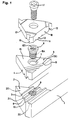
- Fig 1 shows a boring bar or insert holder 1 whose shaft part is not essential for the present invention.
- the front part of the holder comprises a base surface 2, on which are arranged ribs 3 which are intended to fit into grooves 4 on the bottom side of a shim 5.
- the ribs 3 and the grooves 4 may suitably be made in accordance with Swedish patent application 9401429-7 (corresponds to WO 95/29026), which makes it possible to dispense with rear abutment surfaces or points in the insert seat.
- this insert seat does not require any abutment surfaces, which considerably simplifies the manufacturing of the insert seat.
- the shim 5 is fastened on the base surface 2 by a shim screw 6 that has an outer thread 6A threaded into the hole 9, whereby the bottom side of the head of the shim screw presses against the abutment surface 7. Thereby, the flank surfaces of the grooves are pressed against the corresponding flank surfaces 8 of the ribs 3, whereby a small gap is created between the bottom side of the shim on the one hand, and the surfaces 2A disposed between the ribs 3, and surfaces 2B disposed outside the ribs 3, on the other hand.
- the boundary layer or interface comprising the ribs 3 and the grooves 4 is not the boundary layer related to this invention.
- the boundary layer that is essential for the invention is the one between the shim 5 and a cutting insert 10, which boundary layer will now be further described.
- a cutting insert 10 in this case a triangular, single-sided insert for threading, by means of a locking screw 11, which is tightened into the inner thread 6B of the shim screw 6.
- the insert 10 is made of coated or uncoated cemented carbide, although other materials may also occur, e.g., different ceramic materials.
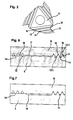
- the bottom side of the cutting insert 10 has grooves 12 in all three corners, which may be seen more clearly in Fig 2. One set of such, substantially parallel grooves is brought into engagement with a set of corresponding ribs 13 on the topside 15 of the shim.
- ribs are formed having substantially planar surfaces or cams 14, which are intended to bear against the top side 15 of a non-ribbed portion of the shim in a way that may be seen more clearly at the left side in Fig 6 and 7.
- Fig 6 and 7 show the principle of the present invention, viz., that the ribs 16 with their planar cams 14 fulfil a double function.
- the ribs 16 serve for wedging and fastening between the ribs 13 of the shim (or of the insert holder, if no shim is used), and on the other hand the planar cams 14 of the ribs 16 function as bearing surfaces which bear against planar non-ribbed portions of the top surface 15 of the shim (or of the insert holder, if no shim is used).
- the flank (side) surfaces 13A of the ribs 13 bear against the flank (side) surfaces 12A of the grooves 12.
- the tops 13B, 14 of the ribs 13 and 16, respectively, are not intended to reach the corresponding groove bottom.
- the cutting insert 10 according to Fig 6 is provided with a central, more deeply recessed middle portion 17, which is not in contact with the shim.
- Fig 7 Another embodiment principle is shown in Fig 7.
- the bottom surface of the insert is planar and in the same level as the planar rib cams 14.
- the shim 5 has been provided with a deeper middle portion 18, in order to obtain the statically well defined abutment of three points or regions at the three corners of the insert.
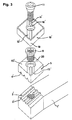
- Fig 3 shows another embodiment according to the present invention. Also this one has a boring bar 1 with a front base surface 2' and ribs 3' which cooperate with grooves 4' on the bottom side of the shim 5'.
- an indexable cutting insert 10' is fastened on the shim 5'.
- the indexable insert 10' is double-sided and is on both sides provided with grooves 12' and ribs 16', the latter having planar cams 14'.
- the opposite side of the insert is provided with similar serrated portions as the visible top surface.
- ribs 16' engage between ribs 13' on the topside 15' of the shim, in order to stay and stabilize the operative cutting corner 19.
- a portion 20 on the topside of the shim may be somewhat raised, in order to bear against the planar rib cams 14' of the insert.
- the ribs 16' of the insert fulfil the double function that is characteristic of the invention.
- the ribs 13 and 13' are located underneath the operative cutting corner and that is also the preferred embodiment. However, they may also be arranged at one of the non-operative corners.
- the invention may also be applied to round cutting inserts.
- the shim 5" bears against the boring bar 1" in the same way as in Fig 1 and 3.
- the cutting insert 10" is double-sided, wherefore the bottom side of the insert is basically identical with the visible topside.
- a number of radial grooves 12" are arranged on the two opposed main sides of the insert. For instance between 2 and 5, suitably 3 as shown in Fig 4, of those grooves enclose an equally large number of ribs 13" on the top side 15" of the shim 5", whereby abutment is accomplished in the above described way on the flank surfaces of the grooves and the ribs, as shown in Fig 6 and 7.
- any other abutment between the insert and the shim may per se take place over the whole surface 15", but preferably this surface is provided with two protruding bearing surfaces 21, which are intended to bear against corresponding sector-shaped, planar surface portions 14" on the round insert.
- a statically well defined three-point or three-region abutment is obtained.
- Fig 5 shows an embodiment that is analogous to the one in Fig 4. The difference is that it lacks a shim. Thus, the ribs 13" and the protrusions 21 are arranged directly on the boring bar.
- a new section of the cutting edge 22 may be indexed by untightening the locking screw and turning the round insert according to Fig 4 and 5 at lest by a twelfth of a revolution, since the grooves 12" divide the main surfaces of the insert into twelve sectors. Thereafter, the locking screw is tightened again.
- fastening arrangement according to the invention is also suitable for milling and drilling.
Landscapes
- Engineering & Computer Science (AREA)
- Mechanical Engineering (AREA)
- Cutting Tools, Boring Holders, And Turrets (AREA)
- Accessories And Tools For Shearing Machines (AREA)
- Joining Of Corner Units Of Frames Or Wings (AREA)
- Turning (AREA)
- Polishing Bodies And Polishing Tools (AREA)
- Processing Of Stones Or Stones Resemblance Materials (AREA)
- Milling Processes (AREA)
- Shearing Machines (AREA)
Applications Claiming Priority (3)
| Application Number | Priority Date | Filing Date | Title |
|---|---|---|---|
| SE9503307A SE509363C2 (sv) | 1995-09-25 | 1995-09-25 | Fastspänningsanordning fjör skärplattor samt skärplatta avsedd för dylik anordning |
| SE9503307 | 1995-09-25 | ||
| PCT/SE1996/001193 WO1997011806A1 (en) | 1995-09-25 | 1996-09-24 | Fastening arrangement for cutting inserts and a cutting insert intended for such an arrangement |
Publications (2)
| Publication Number | Publication Date |
|---|---|
| EP0805731A1 EP0805731A1 (en) | 1997-11-12 |
| EP0805731B1 true EP0805731B1 (en) | 2002-07-17 |
Family
ID=20399580
Family Applications (1)
| Application Number | Title | Priority Date | Filing Date |
|---|---|---|---|
| EP96932128A Expired - Lifetime EP0805731B1 (en) | 1995-09-25 | 1996-09-24 | Fastening arrangement for cutting inserts and a cutting insert intended for such an arrangement |
Country Status (17)
| Country | Link |
|---|---|
| US (1) | US5810518A (enExample) |
| EP (1) | EP0805731B1 (enExample) |
| JP (1) | JPH10509921A (enExample) |
| KR (1) | KR100430734B1 (enExample) |
| CN (1) | CN1081503C (enExample) |
| AT (1) | ATE220590T1 (enExample) |
| AU (1) | AU718678B2 (enExample) |
| BR (1) | BR9606642A (enExample) |
| CA (1) | CA2204638C (enExample) |
| DE (1) | DE69622376T2 (enExample) |
| ES (1) | ES2180796T3 (enExample) |
| IL (1) | IL120771A (enExample) |
| MX (1) | MX9703821A (enExample) |
| PL (1) | PL181543B1 (enExample) |
| RU (1) | RU2164842C2 (enExample) |
| SE (1) | SE509363C2 (enExample) |
| WO (1) | WO1997011806A1 (enExample) |
Families Citing this family (121)
| Publication number | Priority date | Publication date | Assignee | Title |
|---|---|---|---|---|
| US5924826A (en) * | 1994-04-27 | 1999-07-20 | Sandvik Ab | Cutting insert mounted on holder by rib-and-groove coupling |
| SE509339C2 (sv) * | 1994-12-08 | 1999-01-11 | Seco Tools Ab | Verktyg och skär för spånavskiljande bearbetning |
| SE510851C2 (sv) | 1996-12-23 | 1999-06-28 | Sandvik Ab | Skär samt hållare för skärande metallbearbetning |
| SE511390C2 (sv) * | 1997-03-05 | 1999-09-20 | Sandvik Ab | Anordning vid fastspänning av skärplattor för skärande metallbearbetning |
| SE509540C2 (sv) * | 1997-06-30 | 1999-02-08 | Seco Tools Ab | Verktyg |
| SE514254C2 (sv) * | 1997-09-10 | 2001-01-29 | Seco Tools Ab | Verktyg för spånavskiljande bearbetning |
| DE19847227C2 (de) * | 1998-10-14 | 2001-06-28 | Walter Ag | Zerspanungswerkzeug mit formschlüssigem Plattensitz |
| SE518154C2 (sv) | 1999-12-21 | 2002-09-03 | Sandvik Ab | Borr bestående av borrspetsparti som är löstagbart förenat med ett borrskaft |
| SE515635C2 (sv) | 2000-01-27 | 2001-09-17 | Sandvik Ab | Skivfräs jämte skär härför |
| IL136564A (en) * | 2000-06-05 | 2003-12-10 | Iscar Ltd | Cutting tool assembly |
| SE520628C2 (sv) * | 2001-01-09 | 2003-08-05 | Sandvik Ab | Verktyg samt skärkropp för spånavskiljande bearbetning där kopplingsytorna har i varandra passande rillor och åsar |
| SE521183C2 (sv) * | 2001-03-15 | 2003-10-07 | Sandvik Ab | Skärhållare med organ för justering av skärlägeshållaren |
| DE10113707C1 (de) * | 2001-03-16 | 2002-10-10 | Mapal Fab Praezision | Werkzeug zur spanabtragenden Bearbeitung eines Werkstücks aus hochfestem Material |
| IL145574A0 (en) * | 2001-09-24 | 2002-06-30 | Iscar Ltd | Cutting tool and cutting insert therefor |
| JP4232438B2 (ja) * | 2001-12-07 | 2009-03-04 | 三菱マテリアル株式会社 | ドリル |
| SE521579C2 (sv) * | 2002-03-21 | 2003-11-11 | Sandvik Ab | Verktyg samt skär för spånavskiljande bearbetning |
| KR100625900B1 (ko) * | 2002-06-25 | 2006-09-20 | 엔지케이 스파크 플러그 캄파니 리미티드 | 인서트, 홀더 및 절삭공구 |
| SE525712C2 (sv) * | 2002-06-26 | 2005-04-12 | Sandvik Ab | Skär för borrar med spånbrytare |
| KR100994665B1 (ko) * | 2002-07-01 | 2010-11-16 | 쎄코 툴스 에이비 | 칩 제거 가공용 공구의 커플링, 공구, 커팅 헤드 및 홀더 |
| SE525583C2 (sv) | 2002-07-01 | 2005-03-15 | Seco Tools Ab Publ | Koppling med profilerade ytor vid verktyg för spånavskiljande bearbetning |
| SE526174C2 (sv) * | 2002-07-01 | 2005-07-19 | Seco Tools Ab Publ | Koppling vid verktyg för spånavskiljande bearbetning där kopplingsdelarna endast kan monteras i ett läge |
| SE525913C2 (sv) * | 2002-12-20 | 2005-05-24 | Seco Tools Ab | Skär, verktyg samt metod för montering av skär där skäret kan orienteras i önskad position |
| SE526109C2 (sv) † | 2003-03-17 | 2005-07-05 | Seco Tools Ab | Fräsverktyg och indexerbart skär med samverkande utsprång och urtagningar |
| US20040187653A1 (en) * | 2003-03-28 | 2004-09-30 | Terry Chunn | Rotatable seat for cutting tool insert |
| DE10330431B3 (de) * | 2003-07-04 | 2005-01-05 | Schunk Ultraschalltechnik Gmbh | Schweißvorrichtung |
| EP1498200A1 (fr) * | 2003-07-16 | 2005-01-19 | Applitec Moutier S.A. | Outil de coupe |
| US8573901B2 (en) * | 2003-09-02 | 2013-11-05 | Kennametal Inc. | Assembly for rotating a cutting insert during a turning operation and inserts used therein |
| US7156006B2 (en) * | 2003-09-02 | 2007-01-02 | Kennametal Inc. | Method and assembly for rotating a cutting insert during a turning operation and inserts used therein |
| US6991410B2 (en) * | 2003-10-08 | 2006-01-31 | Kennametal Inc. | Toolholder assembly |
| SE526770C2 (sv) * | 2003-10-14 | 2005-11-01 | Sandvik Intellectual Property | Förfarande vid tillverkning av indexerbara skär samt indexerbart skär och skärverktyg med dylikt skär |
| SE526767C2 (sv) * | 2003-10-16 | 2005-11-01 | Sandvik Intellectual Property | Skärverktyg med tillsatskropp med serrationsyta samt förfarande för tillverkning av skärverktyg |
| IL158497A (en) * | 2003-10-20 | 2008-03-20 | Gil Hecht | A tool for removing scratches and cutting for it |
| SE526586C2 (sv) * | 2003-11-25 | 2005-10-11 | Sandvik Intellectual Property | Verktyg för spånavskiljande bearbetning innefattande en han/hon-koppling mellan skärdel och hållardel |
| SE526772C2 (sv) * | 2003-12-23 | 2005-11-01 | Sandvik Intellectual Property | Skärverktyg med serrationskopplingsytor samt förfarande för framställning av dessa |
| SE526399C2 (sv) * | 2004-01-30 | 2005-09-06 | Sandvik Intellectual Property | Skärverktyg jämte del därtill med kopplingsytor med rillor samt tillverkningsförfarande för dessa |
| US20050173023A1 (en) * | 2004-02-11 | 2005-08-11 | Guofang Cao | Configurations and designs for stump grinding teeth and corresponding holding |
| SE527851C2 (sv) | 2004-02-11 | 2006-06-20 | Sandvik Intellectual Property | Skärverktyg, skär samt del till skärverktyg med serrationskopplingsytor |
| SE526645C2 (sv) * | 2004-02-20 | 2005-10-18 | Sandvik Intellectual Property | Spårfräs |
| SE527850C2 (sv) * | 2004-02-24 | 2006-06-20 | Sandvik Intellectual Property | Skärverktyg samt grundkropp med kopplingsytor försedda med åsar |
| US7325471B2 (en) * | 2004-09-07 | 2008-02-05 | Kennametal Inc. | Toolholder and cutting insert for a toolholder assembly |
| SE527613C2 (sv) * | 2004-10-15 | 2006-04-25 | Seco Tools Ab | Verktyg för skärande bearbetning med en underläggsplatta med urtagningar |
| JP4353067B2 (ja) * | 2004-10-27 | 2009-10-28 | 三菱マテリアル株式会社 | ねじ切り切削用インサート |
| DE102005007676B3 (de) | 2005-02-19 | 2006-07-13 | Mws Schneidwerkzeuge Gmbh & Co. Kg | Anordnung und Befestigung von Schneidplatten |
| SE528811C2 (sv) * | 2005-03-16 | 2007-02-20 | Sandvik Intellectual Property | Skär och verktyg för spånavskiljande bearbetning med vinklade ingreppsmedel, samt tillsats för dylika verktyg |
| US7040843B1 (en) * | 2005-03-17 | 2006-05-09 | Great Lakes Custom Tool Mfg., Inc. | Flooring hollow back relief cutting tool and method |
| SE528710C2 (sv) * | 2005-06-01 | 2007-01-30 | Sandvik Intellectual Property | Indexerbart frässkär med kopplingsmedlet anordnat på en släppningsyta |
| DE102005032653B3 (de) * | 2005-07-13 | 2006-11-30 | Fette Gmbh | Verfahren zur Herstellung einer formschlüssigen Verbindung zwischen einem Werkzeugeinsatz und einem Werkzeugträger eines rotierenden Werkzeugs |
| DE102006052701A1 (de) * | 2006-01-09 | 2007-07-26 | Ceramtec Ag Innovative Ceramic Engineering | Formschlüssig befestigte Schneidplatte auf einer Stützplatte |
| USD550730S1 (en) | 2006-02-28 | 2007-09-11 | Manchester Tool Company | Cutting insert support/clamp |
| USD558802S1 (en) | 2006-02-28 | 2008-01-01 | Kennametal Inc. | Tool holder |
| WO2007100907A2 (en) | 2006-02-28 | 2007-09-07 | Kennametal Inc. | Tool holder assembly |
| DE102006017074A1 (de) * | 2006-04-10 | 2007-10-11 | Walter Ag | Unterlegplatte für doppelseitige Wendeschneideinsätze |
| SE0600876L (sv) * | 2006-04-20 | 2007-10-21 | Sandvik Intellectual Property | Verktyg och skär för spånavskiljande bearbetning med primära och sekundära ingreppsmedel med rotationssymmetrisk form |
| US7390150B2 (en) * | 2006-05-03 | 2008-06-24 | Valenite Llc | Cutting tool with adjustable indexable cutting insert |
| US20070274794A1 (en) * | 2006-05-26 | 2007-11-29 | Cirino Thomas J | Oblique angle serration location and drive interface |
| US7357604B2 (en) * | 2006-06-20 | 2008-04-15 | Kennametal Inc. | Indexable cutting insert with positive axial rake angle and multiple cutting edges |
| SE530631C2 (sv) * | 2006-12-12 | 2008-07-22 | Sandvik Intellectual Property | Verktyg och skär för spånavskiljande bearbetning |
| US7607867B2 (en) * | 2006-12-15 | 2009-10-27 | Sandvik Intellectual Property Ab | Tooling insert with mating surface |
| SE530698C2 (sv) * | 2006-12-21 | 2008-08-19 | Sandvik Intellectual Property | Svarvverktyg, samt grundkropp och underläggsplatta för dylika verktyg |
| SE530701C2 (sv) * | 2006-12-21 | 2008-08-19 | Sandvik Intellectual Property | Svarvverktyg och svarvskär där ingreppsorganen i skäret är lokaliserade i entriangel |
| SE530808C2 (sv) * | 2007-01-31 | 2008-09-16 | Sandvik Intellectual Property | Verktyg för spånavskiljande bearbetning, samt skär och grundkropp härför |
| DE102007022535A1 (de) * | 2007-05-14 | 2008-11-20 | Kennametal Inc. | Achtschneidiger Schneideinsatz sowie Werkzeughalter hierfür |
| DE102007022536A1 (de) * | 2007-05-14 | 2008-11-20 | Kennametal Inc. | Achtschneidiger Schneideinsatz sowie Werkzeughalter hierfür |
| FR2916150B1 (fr) * | 2007-05-16 | 2009-07-31 | Safety Production Soc Par Acti | Porte-outil et plaquette de coupe a nez de centrage |
| RU2440872C2 (ru) * | 2007-06-07 | 2012-01-27 | Вмакс, Инк. | Регулируемое сверло с механическим креплением многогранных режущих пластин |
| IL185047A (en) * | 2007-08-05 | 2011-09-27 | Iscar Ltd | Cutting Tools |
| IL185048A (en) * | 2007-08-05 | 2011-07-31 | Iscar Ltd | Cutting tool and cutting tool for it |
| RU2349425C1 (ru) * | 2007-11-27 | 2009-03-20 | Нина Алексеевна Корюкина | Режущая пластина и сборный режущий инструмент (варианты) |
| IL188502A (en) * | 2007-12-30 | 2012-05-31 | Iscar Ltd | Cutting insert and cutting tool therefor |
| SE532002C2 (sv) | 2008-02-05 | 2009-09-22 | Sandvik Intellectual Property | Verktyg för spånavskiljande bearbetning, samt grundkropp och skär härför |
| RU2364476C1 (ru) * | 2008-04-21 | 2009-08-20 | Нина Алексеевна Корюкина | Сборный режущий инструмент (варианты) |
| DE102008037915B3 (de) * | 2008-08-14 | 2009-08-13 | Kennametal Inc. | Wendeschneidplatte |
| US8454277B2 (en) | 2008-12-18 | 2013-06-04 | Kennametal Inc. | Toolholder and toolholder assembly with elongated seating pads |
| US7922427B2 (en) * | 2008-12-18 | 2011-04-12 | Kennametal Inc. | Toolholder and toolholder assembly with elongated seating pads |
| CN101890511B (zh) * | 2009-05-22 | 2012-12-26 | 王登宏 | 双刃刀具组 |
| CN102858485B (zh) * | 2009-10-15 | 2015-05-20 | 山特维克有限公司 | 具有定位装置的多齿可转位刀片及具有该多齿可转位刀片的材料移除刀具 |
| DE102009051073A1 (de) * | 2009-10-28 | 2011-05-12 | Kennametal Inc. | Mehrfachwechselschneidplatte für ein Bohrwerkzeug |
| US8573903B2 (en) * | 2009-11-03 | 2013-11-05 | Kennametal Inc. | Round cutting insert with anti-rotation feature |
| US8277153B2 (en) * | 2009-12-02 | 2012-10-02 | Kennametal Inc. | Cutting insert and shim for heavy machining operations |
| KR101154704B1 (ko) * | 2010-02-19 | 2012-06-08 | 대구텍 유한회사 | 홈에 의해 분할된 절삭날을 갖는 절삭 인서트 및 이를 구비한 밀링 커터 |
| US20110262232A1 (en) * | 2010-04-23 | 2011-10-27 | Chin-Chiu Chen | Lathe blade assembly |
| US9517509B2 (en) * | 2010-12-25 | 2016-12-13 | Kyocera Corporation | Cutting tool and method of manufacturing machined product using the same |
| US8657539B2 (en) | 2011-03-28 | 2014-02-25 | Kennametal Inc. | Round cutting insert with reverse anti-rotation feature |
| JP5754331B2 (ja) * | 2011-09-30 | 2015-07-29 | 三菱日立ツール株式会社 | 刃先交換式切削工具 |
| BR112014008368B1 (pt) * | 2011-10-07 | 2020-12-08 | Tungaloy Corporation | ferramenta de corte com aresta de corte substituível |
| JP2015006698A (ja) * | 2011-11-02 | 2015-01-15 | 株式会社タンガロイ | 刃先交換式切削工具 |
| USD709110S1 (en) | 2012-04-24 | 2014-07-15 | Kennametal Inc. | Cutting insert |
| US8858130B2 (en) | 2012-04-24 | 2014-10-14 | Kennametal Inc. | Indexable circular cutting insert |
| EP2664399B1 (en) | 2012-05-15 | 2017-01-04 | VARGUS Ltd. | Cutting tool |
| DE102012017025B4 (de) * | 2012-08-28 | 2018-05-30 | Kennametal Inc. | Werkzeughalter für einen Schneideinsatz und Baugruppe mit einem solchen Werkzeughalter |
| JP6079991B2 (ja) * | 2012-09-20 | 2017-02-15 | Toto株式会社 | 静圧気体軸受 |
| US9120154B2 (en) * | 2013-02-14 | 2015-09-01 | Iscar, Ltd. | Single-sided square-shaped indexable cutting insert and cutting tool |
| US9120156B2 (en) * | 2013-03-26 | 2015-09-01 | Iscar, Ltd. | Rhombus-shaped indexable cutting insert and cutting tool |
| DE202013102510U1 (de) * | 2013-06-11 | 2014-06-12 | Pokolm Frästechnik GmbH & Co. KG | Wendeschneidplatte für ein Fräswerkzeug zum spanabhebenden Bearbeiten von Werkstücken |
| US9375793B2 (en) | 2013-10-29 | 2016-06-28 | Kennametal Inc. | Cutting insert for heavy machining operations |
| US9339873B2 (en) * | 2013-12-11 | 2016-05-17 | Iscar, Ltd. | Cutting insert having a dovetail anti-slip arrangement |
| US9481038B2 (en) * | 2013-12-11 | 2016-11-01 | Iscar, Ltd. | Cutting insert having a dovetail anti-slip arrangement |
| KR101519101B1 (ko) * | 2013-12-24 | 2015-05-11 | 한국야금 주식회사 | 인서트 및 이를 체결하는 공구 홀더 |
| US9421622B2 (en) * | 2014-01-14 | 2016-08-23 | Iscar, Ltd. | Indexable central drill insert and cutting tool therefor |
| CN104227114B (zh) * | 2014-07-21 | 2016-08-24 | 株洲钻石切削刀具股份有限公司 | 一种铣削刀具 |
| TWI494181B (zh) * | 2014-07-28 | 2015-08-01 | 張新添 | Discarded milling cutter structure |
| DE102014119094A1 (de) * | 2014-12-18 | 2016-06-23 | Hartmetall-Werkzeugfabrik Paul Horn Gmbh | Spanabhebendes Werkzeug |
| EP3311946B1 (en) * | 2015-06-19 | 2020-02-19 | Tungaloy Corporation | Tool body in combination with a cutting insert and cutting tool |
| EP3153260B1 (en) * | 2015-10-09 | 2018-05-23 | Sandvik Intellectual Property AB | Turning insert and method |
| US10160040B2 (en) * | 2015-11-18 | 2018-12-25 | Iscar, Ltd. | Cutting tool and triangular-shaped indexable cutting insert therefor |
| RU2618291C1 (ru) * | 2016-02-15 | 2017-05-03 | Нина Алексеевна Корюкина | Режущая пластина и режущий инструмент |
| EP3246117A1 (en) * | 2016-05-20 | 2017-11-22 | Seco Tools Ab | Cutting tool and shim |
| US10556278B2 (en) * | 2016-08-16 | 2020-02-11 | Kennametal Inc. | Tool body for a shell end mill and cutting tool |
| EP3501701B1 (de) * | 2017-12-22 | 2020-07-29 | Ceratizit Austria Gesellschaft m.b.H. | Werkzeugsystem und verfahren zur drehbearbeitung |
| US11484949B2 (en) | 2018-10-10 | 2022-11-01 | Sumitomo Electric Hardmetal Corp. | Cutting insert and cutting tool |
| US11090740B2 (en) * | 2019-02-12 | 2021-08-17 | Iscar, Ltd. | Rotary cutting body having insert pocket with seat surface provided with a plurality of abutment elements and rotary cutting tool |
| EP3702075B1 (en) | 2019-02-28 | 2023-12-20 | AB Sandvik Coromant | Turning insert for metal cutting |
| EP3738698B1 (en) * | 2019-05-16 | 2022-11-02 | AB Sandvik Coromant | Turning insert for metal cutting, a cutting tool and a method to machine a metal workpiece |
| EP3738697B1 (en) * | 2019-05-16 | 2023-02-22 | AB Sandvik Coromant | Turning tool for metal cutting |
| JP6919824B2 (ja) * | 2020-01-15 | 2021-08-18 | 株式会社タンガロイ | 切削インサート及び該切削インサートを用いた旋削工具 |
| CN115735693A (zh) * | 2020-08-21 | 2023-03-07 | 杨永波 | 畜牧养殖系统 |
| US20230364691A1 (en) * | 2021-04-26 | 2023-11-16 | Kennametal Inc. | Cutting tool comprising toolholder and round cutting insert and method for repositioning the round cutting insert in a pocket of the toolholder |
| US11786982B2 (en) | 2021-04-26 | 2023-10-17 | Kennametal Inc. | Cutting tool comprising toolholder and round cutting insert and method for repositioning the round cutting insert in a pocket of the toolholder |
| US11717895B2 (en) * | 2021-05-21 | 2023-08-08 | Taegutec Ltd. | Cutting insert and cutting tool assembly including same |
| CN116833436B (zh) * | 2023-09-01 | 2023-11-03 | 齐鲁工业大学(山东省科学院) | 一种机夹可转位刀具用梯度刚度刀垫 |
| US20250235933A1 (en) | 2024-01-23 | 2025-07-24 | Iscar, Ltd. | Cutting Tool Having Cutting Insert and Insert Holder With Interface Having a Pair of Male and Female Type Engagement Members |
Family Cites Families (24)
| Publication number | Priority date | Publication date | Assignee | Title |
|---|---|---|---|---|
| DE183293C (enExample) * | ||||
| US1621226A (en) * | 1923-09-19 | 1927-03-15 | Armstrong Bros Tool Co | Milling cutter |
| US1681675A (en) * | 1925-05-16 | 1928-08-21 | Frank P Miller | Rotary cutter |
| US1629667A (en) * | 1926-10-15 | 1927-05-24 | James D Knipple | Metal-cutting tool |
| SU52003A1 (ru) * | 1935-12-14 | 1936-11-30 | С.И. Пономарев | Державка дл тангенциального резца |
| US2140941A (en) * | 1936-10-27 | 1938-12-20 | O K Tool Co Inc | Triple adjustment shankless tool bit and holder therefor |
| US2453464A (en) * | 1945-05-31 | 1948-11-09 | Apex Tool & Cutter Company | Toolholder |
| SE324272B (enExample) * | 1968-09-24 | 1970-05-25 | Fagersta Bruks Ab | |
| US3829943A (en) * | 1971-02-19 | 1974-08-20 | Fansteel Inc | Threading tool |
| US4315706A (en) * | 1980-04-07 | 1982-02-16 | General Electric Company | Holder assembly for an indexable insert for use in a cutting tool |
| US4437802A (en) * | 1981-09-14 | 1984-03-20 | Hall Jr John J | Boring tool having a detachable cutting blade |
| DE3219019A1 (de) * | 1982-05-19 | 1983-11-24 | Zinner GmbH, 8500 Nürnberg | Ein- und mehrfachstechwerkzeug |
| DE3333495A1 (de) * | 1983-09-16 | 1985-03-28 | J. Kühn GmbH & Co Präzisionswerkzeug KG, 4270 Dorsten | Drehbares zerspanungswerkzeug, insbesondere ausbohrkopf od. dgl. |
| DE3446455A1 (de) * | 1984-12-20 | 1986-06-26 | Otto 7210 Rottweil Dieterle | Drehmeissel mit wendeschneidplatte |
| DE3533125A1 (de) * | 1985-09-17 | 1987-03-19 | Valenite Modco Gmbh | Fraeser fuer das hochgeschwindigkeitsfraesen |
| DE3617119A1 (de) * | 1986-05-22 | 1987-11-26 | Gte Valeron Corp | Umsetzbare wendeschneidplatte |
| SU1526918A1 (ru) * | 1987-04-13 | 1989-12-07 | Производственное Объединение "Ворошиловградский Тепловозостроительный Завод Им.Октябрьской Революции" | Многогранна режуща пластина |
| US5028175A (en) * | 1988-03-21 | 1991-07-02 | Gte Valenite Corporation | Indexable insert for roughing and finishing |
| US5236288A (en) * | 1991-11-08 | 1993-08-17 | National Carbide Outlet, Inc. | Cutter with positively locked round inserts |
| RU2028875C1 (ru) * | 1992-07-28 | 1995-02-20 | Малое предприятие "Пикон" | Режущий инструмент со сменной перетачиваемой пластиной |
| JPH06126511A (ja) * | 1992-10-13 | 1994-05-10 | Toyota Motor Corp | スローアウェイチップ |
| DE4423861A1 (de) * | 1993-05-28 | 1994-12-01 | Holger Groeschel | Befestigungsvorrichtung für auswechselbare, mit zylindrischem Zapfen versehene Schneideinsätze |
| US5469902A (en) * | 1993-09-13 | 1995-11-28 | American Knife, Inc. | Chipper knife and knife holder assembly |
| SE504205C2 (sv) * | 1994-04-27 | 1996-12-09 | Sandvik Ab | Skär med rillor |
-
1995
- 1995-09-25 SE SE9503307A patent/SE509363C2/sv not_active IP Right Cessation
-
1996
- 1996-09-24 BR BR9606642A patent/BR9606642A/pt not_active IP Right Cessation
- 1996-09-24 US US08/719,976 patent/US5810518A/en not_active Expired - Lifetime
- 1996-09-24 AU AU71028/96A patent/AU718678B2/en not_active Expired
- 1996-09-24 RU RU97110201/02A patent/RU2164842C2/ru active
- 1996-09-24 WO PCT/SE1996/001193 patent/WO1997011806A1/en not_active Ceased
- 1996-09-24 MX MX9703821A patent/MX9703821A/es unknown
- 1996-09-24 IL IL12077196A patent/IL120771A/xx not_active IP Right Cessation
- 1996-09-24 KR KR1019970703493A patent/KR100430734B1/ko not_active Expired - Lifetime
- 1996-09-24 AT AT96932128T patent/ATE220590T1/de active
- 1996-09-24 PL PL96320455A patent/PL181543B1/pl unknown
- 1996-09-24 DE DE69622376T patent/DE69622376T2/de not_active Expired - Lifetime
- 1996-09-24 EP EP96932128A patent/EP0805731B1/en not_active Expired - Lifetime
- 1996-09-24 CN CN96191102A patent/CN1081503C/zh not_active Expired - Lifetime
- 1996-09-24 CA CA002204638A patent/CA2204638C/en not_active Expired - Lifetime
- 1996-09-24 JP JP9513350A patent/JPH10509921A/ja active Pending
- 1996-09-24 ES ES96932128T patent/ES2180796T3/es not_active Expired - Lifetime
Also Published As
| Publication number | Publication date |
|---|---|
| ATE220590T1 (de) | 2002-08-15 |
| CN1081503C (zh) | 2002-03-27 |
| AU7102896A (en) | 1997-04-17 |
| PL181543B1 (pl) | 2001-08-31 |
| KR100430734B1 (ko) | 2004-09-08 |
| CA2204638C (en) | 2006-01-31 |
| DE69622376T2 (de) | 2003-03-06 |
| IL120771A0 (en) | 1997-09-30 |
| PL320455A1 (en) | 1997-09-29 |
| JPH10509921A (ja) | 1998-09-29 |
| AU718678B2 (en) | 2000-04-20 |
| WO1997011806A1 (en) | 1997-04-03 |
| SE509363C2 (sv) | 1999-01-18 |
| SE9503307D0 (sv) | 1995-09-25 |
| IL120771A (en) | 2000-07-26 |
| ES2180796T3 (es) | 2003-02-16 |
| US5810518A (en) | 1998-09-22 |
| BR9606642A (pt) | 1997-09-30 |
| DE69622376D1 (de) | 2002-08-22 |
| SE9503307L (sv) | 1997-03-26 |
| RU2164842C2 (ru) | 2001-04-10 |
| CN1165492A (zh) | 1997-11-19 |
| MX9703821A (es) | 1997-12-31 |
| CA2204638A1 (en) | 1997-04-03 |
| EP0805731A1 (en) | 1997-11-12 |
Similar Documents
| Publication | Publication Date | Title |
|---|---|---|
| EP0805731B1 (en) | Fastening arrangement for cutting inserts and a cutting insert intended for such an arrangement | |
| US6343898B1 (en) | Cutting insert and holder for metal cutting machining | |
| EP0961666B1 (en) | Cutting insert for chip-breaking machining of metals | |
| US5931613A (en) | Cutting insert and tool holder therefor | |
| US6929429B2 (en) | Milling tool and cutting insert therefor | |
| EP0730926B1 (en) | Tool holder | |
| US7819610B2 (en) | Tool for chip removing machining, as well as a cutting insert and a basic body therefor | |
| KR100359963B1 (ko) | 절삭삽입체와이를삽입체홀더상에체결하기위한절삭삽입체와삽입체홀더의조립체 | |
| US6543970B1 (en) | Double negative cutting insert for tools for chip removing machining | |
| US6379087B1 (en) | Cutting insert with split face clamping surfaces and toolholder therefor | |
| EP0760726B1 (en) | A cutting insert for a milling cutter | |
| KR100430348B1 (ko) | 금속절삭용공구 | |
| JP3970929B2 (ja) | 荒削り及び精密削りのための切削チップ | |
| US7201545B2 (en) | Tool, a cutting insert, a shim and use of the cutting insert | |
| EP2664399B1 (en) | Cutting tool | |
| US4674924A (en) | Single-sided cutting insert | |
| US4687383A (en) | Insert rotary cutter |
Legal Events
| Date | Code | Title | Description |
|---|---|---|---|
| PUAI | Public reference made under article 153(3) epc to a published international application that has entered the european phase |
Free format text: ORIGINAL CODE: 0009012 |
|
| 17P | Request for examination filed |
Effective date: 19970426 |
|
| AK | Designated contracting states |
Kind code of ref document: A1 Designated state(s): AT BE CH DE DK ES FI FR GB IE IT LI LU NL PT SE |
|
| 17Q | First examination report despatched |
Effective date: 19990715 |
|
| GRAG | Despatch of communication of intention to grant |
Free format text: ORIGINAL CODE: EPIDOS AGRA |
|
| GRAG | Despatch of communication of intention to grant |
Free format text: ORIGINAL CODE: EPIDOS AGRA |
|
| GRAH | Despatch of communication of intention to grant a patent |
Free format text: ORIGINAL CODE: EPIDOS IGRA |
|
| GRAH | Despatch of communication of intention to grant a patent |
Free format text: ORIGINAL CODE: EPIDOS IGRA |
|
| GRAA | (expected) grant |
Free format text: ORIGINAL CODE: 0009210 |
|
| AK | Designated contracting states |
Kind code of ref document: B1 Designated state(s): AT BE CH DE DK ES FI FR GB IE IT LI LU NL PT SE |
|
| PG25 | Lapsed in a contracting state [announced via postgrant information from national office to epo] |
Ref country code: NL Free format text: LAPSE BECAUSE OF FAILURE TO SUBMIT A TRANSLATION OF THE DESCRIPTION OR TO PAY THE FEE WITHIN THE PRESCRIBED TIME-LIMIT Effective date: 20020717 Ref country code: LI Free format text: LAPSE BECAUSE OF FAILURE TO SUBMIT A TRANSLATION OF THE DESCRIPTION OR TO PAY THE FEE WITHIN THE PRESCRIBED TIME-LIMIT Effective date: 20020717 Ref country code: FI Free format text: LAPSE BECAUSE OF FAILURE TO SUBMIT A TRANSLATION OF THE DESCRIPTION OR TO PAY THE FEE WITHIN THE PRESCRIBED TIME-LIMIT Effective date: 20020717 Ref country code: CH Free format text: LAPSE BECAUSE OF FAILURE TO SUBMIT A TRANSLATION OF THE DESCRIPTION OR TO PAY THE FEE WITHIN THE PRESCRIBED TIME-LIMIT Effective date: 20020717 Ref country code: BE Free format text: LAPSE BECAUSE OF FAILURE TO SUBMIT A TRANSLATION OF THE DESCRIPTION OR TO PAY THE FEE WITHIN THE PRESCRIBED TIME-LIMIT Effective date: 20020717 |
|
| REF | Corresponds to: |
Ref document number: 220590 Country of ref document: AT Date of ref document: 20020815 Kind code of ref document: T |
|
| REG | Reference to a national code |
Ref country code: GB Ref legal event code: FG4D |
|
| REG | Reference to a national code |
Ref country code: CH Ref legal event code: EP |
|
| REG | Reference to a national code |
Ref country code: IE Ref legal event code: FG4D |
|
| REF | Corresponds to: |
Ref document number: 69622376 Country of ref document: DE Date of ref document: 20020822 |
|
| PGFP | Annual fee paid to national office [announced via postgrant information from national office to epo] |
Ref country code: SE Payment date: 20020904 Year of fee payment: 7 |
|
| PG25 | Lapsed in a contracting state [announced via postgrant information from national office to epo] |
Ref country code: LU Free format text: LAPSE BECAUSE OF NON-PAYMENT OF DUE FEES Effective date: 20020924 Ref country code: IE Free format text: LAPSE BECAUSE OF NON-PAYMENT OF DUE FEES Effective date: 20020924 |
|
| PG25 | Lapsed in a contracting state [announced via postgrant information from national office to epo] |
Ref country code: SE Free format text: LAPSE BECAUSE OF FAILURE TO SUBMIT A TRANSLATION OF THE DESCRIPTION OR TO PAY THE FEE WITHIN THE PRESCRIBED TIME-LIMIT Effective date: 20021017 Ref country code: PT Free format text: LAPSE BECAUSE OF FAILURE TO SUBMIT A TRANSLATION OF THE DESCRIPTION OR TO PAY THE FEE WITHIN THE PRESCRIBED TIME-LIMIT Effective date: 20021017 Ref country code: DK Free format text: LAPSE BECAUSE OF FAILURE TO SUBMIT A TRANSLATION OF THE DESCRIPTION OR TO PAY THE FEE WITHIN THE PRESCRIBED TIME-LIMIT Effective date: 20021017 |
|
| NLV1 | Nl: lapsed or annulled due to failure to fulfill the requirements of art. 29p and 29m of the patents act | ||
| ET | Fr: translation filed | ||
| REG | Reference to a national code |
Ref country code: CH Ref legal event code: PL |
|
| REG | Reference to a national code |
Ref country code: ES Ref legal event code: FG2A Ref document number: 2180796 Country of ref document: ES Kind code of ref document: T3 |
|
| PLBE | No opposition filed within time limit |
Free format text: ORIGINAL CODE: 0009261 |
|
| STAA | Information on the status of an ep patent application or granted ep patent |
Free format text: STATUS: NO OPPOSITION FILED WITHIN TIME LIMIT |
|
| 26N | No opposition filed |
Effective date: 20030422 |
|
| REG | Reference to a national code |
Ref country code: IE Ref legal event code: MM4A |
|
| REG | Reference to a national code |
Ref country code: GB Ref legal event code: 732E |
|
| REG | Reference to a national code |
Ref country code: GB Ref legal event code: 732E |
|
| REG | Reference to a national code |
Ref country code: FR Ref legal event code: TP |
|
| REG | Reference to a national code |
Ref country code: FR Ref legal event code: TP |
|
| REG | Reference to a national code |
Ref country code: FR Ref legal event code: PLFP Year of fee payment: 20 |
|
| PGFP | Annual fee paid to national office [announced via postgrant information from national office to epo] |
Ref country code: GB Payment date: 20150923 Year of fee payment: 20 Ref country code: ES Payment date: 20150810 Year of fee payment: 20 Ref country code: DE Payment date: 20150916 Year of fee payment: 20 |
|
| PGFP | Annual fee paid to national office [announced via postgrant information from national office to epo] |
Ref country code: FR Payment date: 20150811 Year of fee payment: 20 Ref country code: AT Payment date: 20150825 Year of fee payment: 20 |
|
| PGFP | Annual fee paid to national office [announced via postgrant information from national office to epo] |
Ref country code: IT Payment date: 20150925 Year of fee payment: 20 |
|
| REG | Reference to a national code |
Ref country code: DE Ref legal event code: R071 Ref document number: 69622376 Country of ref document: DE |
|
| REG | Reference to a national code |
Ref country code: GB Ref legal event code: PE20 Expiry date: 20160923 |
|
| PG25 | Lapsed in a contracting state [announced via postgrant information from national office to epo] |
Ref country code: GB Free format text: LAPSE BECAUSE OF EXPIRATION OF PROTECTION Effective date: 20160923 |
|
| REG | Reference to a national code |
Ref country code: AT Ref legal event code: MK07 Ref document number: 220590 Country of ref document: AT Kind code of ref document: T Effective date: 20160924 |
|
| REG | Reference to a national code |
Ref country code: ES Ref legal event code: FD2A Effective date: 20170102 |
|
| PG25 | Lapsed in a contracting state [announced via postgrant information from national office to epo] |
Ref country code: ES Free format text: LAPSE BECAUSE OF EXPIRATION OF PROTECTION Effective date: 20160925 |