EP3738698B1 - Turning insert for metal cutting, a cutting tool and a method to machine a metal workpiece - Google Patents
Turning insert for metal cutting, a cutting tool and a method to machine a metal workpiece Download PDFInfo
- Publication number
- EP3738698B1 EP3738698B1 EP19174816.9A EP19174816A EP3738698B1 EP 3738698 B1 EP3738698 B1 EP 3738698B1 EP 19174816 A EP19174816 A EP 19174816A EP 3738698 B1 EP3738698 B1 EP 3738698B1
- Authority
- EP
- European Patent Office
- Prior art keywords
- protrusions
- turning
- insert
- turning insert
- center axis
- Prior art date
- Legal status (The legal status is an assumption and is not a legal conclusion. Google has not performed a legal analysis and makes no representation as to the accuracy of the status listed.)
- Active
Links
- 239000002184 metal Substances 0.000 title claims description 30
- 238000000034 method Methods 0.000 title claims description 4
- 230000008878 coupling Effects 0.000 description 2
- 238000010168 coupling process Methods 0.000 description 2
- 238000005859 coupling reaction Methods 0.000 description 2
- 238000003754 machining Methods 0.000 description 2
- 239000000463 material Substances 0.000 description 2
- 229910052582 BN Inorganic materials 0.000 description 1
- PZNSFCLAULLKQX-UHFFFAOYSA-N Boron nitride Chemical compound N#B PZNSFCLAULLKQX-UHFFFAOYSA-N 0.000 description 1
- 238000005452 bending Methods 0.000 description 1
- 239000000919 ceramic Substances 0.000 description 1
- 230000007423 decrease Effects 0.000 description 1
- 238000005192 partition Methods 0.000 description 1
- 230000009466 transformation Effects 0.000 description 1
Images


Classifications
-
- B—PERFORMING OPERATIONS; TRANSPORTING
- B23—MACHINE TOOLS; METAL-WORKING NOT OTHERWISE PROVIDED FOR
- B23B—TURNING; BORING
- B23B27/00—Tools for turning or boring machines; Tools of a similar kind in general; Accessories therefor
- B23B27/14—Cutting tools of which the bits or tips or cutting inserts are of special material
- B23B27/16—Cutting tools of which the bits or tips or cutting inserts are of special material with exchangeable cutting bits or cutting inserts, e.g. able to be clamped
- B23B27/1614—Cutting tools of which the bits or tips or cutting inserts are of special material with exchangeable cutting bits or cutting inserts, e.g. able to be clamped with plate-like cutting inserts of special shape clamped against the walls of the recess in the shank by a clamping member acting upon the wall of a hole in the insert
-
- B—PERFORMING OPERATIONS; TRANSPORTING
- B23—MACHINE TOOLS; METAL-WORKING NOT OTHERWISE PROVIDED FOR
- B23B—TURNING; BORING
- B23B2200/00—Details of cutting inserts
- B23B2200/04—Overall shape
- B23B2200/0461—Round
-
- B—PERFORMING OPERATIONS; TRANSPORTING
- B23—MACHINE TOOLS; METAL-WORKING NOT OTHERWISE PROVIDED FOR
- B23B—TURNING; BORING
- B23B2200/00—Details of cutting inserts
- B23B2200/16—Supporting or bottom surfaces
- B23B2200/165—Supporting or bottom surfaces with one or more grooves
-
- B—PERFORMING OPERATIONS; TRANSPORTING
- B23—MACHINE TOOLS; METAL-WORKING NOT OTHERWISE PROVIDED FOR
- B23B—TURNING; BORING
- B23B2200/00—Details of cutting inserts
- B23B2200/32—Chip breaking or chip evacuation
- B23B2200/321—Chip breaking or chip evacuation by chip breaking projections
-
- B—PERFORMING OPERATIONS; TRANSPORTING
- B23—MACHINE TOOLS; METAL-WORKING NOT OTHERWISE PROVIDED FOR
- B23B—TURNING; BORING
- B23B2205/00—Fixation of cutting inserts in holders
- B23B2205/12—Seats for cutting inserts
-
- B—PERFORMING OPERATIONS; TRANSPORTING
- B23—MACHINE TOOLS; METAL-WORKING NOT OTHERWISE PROVIDED FOR
- B23B—TURNING; BORING
- B23B2205/00—Fixation of cutting inserts in holders
- B23B2205/16—Shims
Definitions
- the present invention belongs to the technical field of metal cutting. More specifically the present invention belongs to the field of tools for turning comprising a round turning insert.
- the present invention refers to a turning insert according to the preamble of claim 1.
- An example of such a turning insert is disclosed by WO 2004/056515 A .
- a turning tool is used to remove material from the metal work piece.
- the turning tool normally comprises a turning insert.
- a turning insert may have different shape, depending on factors such as the type of turning operation and component design.
- One common type of turning inserts are round turning inserts, i.e. turning inserts having a circular cutting edge.
- US7607867B2 disclose a turning tool comprising a turning insert having a circular cutting edge.
- the bottom surface of the turning insert comprises a plurality of radial grooves.
- WO 2004/056515 A discloses a turning tool having a round turning insert which comprises a built-in positioning of a chip breaker portion.
- the lower side of the turning insert comprises a number of indexing portions in the form of radial grooves, provided at even partition, and intended for indexing of the cutting insert.
- An upper side of a shim has a projection or a shoulder having a radial dimension to prevent rotation relative to an active, cooperating groove of the turning insert.
- the turning insert should be rotated to a fixed position to achieve good chip breaking.
- the inventors have found that there is a need for an improved turning insert.
- An object of the present invention is to provide a turning insert having a circular cutting edge, which can be indexable in predetermined positions, which can give improved chip breaking both at low and high feed rates when used in more than one feed direction.
- At least one of said objects is achieved by a turning insert having the features of claim 1.
- the first protrusions bends the chip so it becomes more fragile.
- the chip thickness varies.
- the thin part of the chip is controlled effeicietly solely by the elongated first protrusions.
- the turning insert preferably comprises a wear resistant material such as cemented carbide, cubic boron nitride or ceramic.
- the top surface comprises a rake surface.
- the bottom surface comprises a seating surface.
- the reference plane is mid-way between the top and bottom surfaces.
- the center axis intersecting the top and bottom surfaces is perpendicular to the reference plane.
- a through hole is concentric with the center axis.
- the side surface connecting the top surface and the bottom surface comprises a clearance surface.
- the side surface is preferably conical. In other words, an area of the top surface is preferably greater than an area of the bottom surface.
- a cutting edge is adjacent to, i.e. connects or borders to the top surface and the side surface.
- the cutting edge is 360° circular in a top view and is concentric in relation to or with the center axis.
- the cutting edge may be entirely located in a plane parallel to the reference plane.
- the top surface comprises a set, i.e. a number of spaced apart first protrusions.
- a protrusion is a portion of the top surface which protrudes upwards, i.e. in a direction away from the reference plane, in relation to surrounding or adjacent portions of the top surface.
- Said first protrusions are spaced apart from the cutting edge.
- a greatest distance from the reference plane to the first protrusions is greater than a distance from the reference plane to the cutting edge, where said distances are measured perpendicular to the reference plane.
- the first protrusions are at least partly above the cutting edge, where the top surface is upwards and the bottom surface is downwards.
- the bottom surface comprises a set of radial grooves.
- said grooves extend towards the center axis.
- Said grooves preferably intersect the side surface.
- Said grooves preferably have a constant width and height along the length of the groove.
- the set of radial grooves are evenly distributed around the center axis.
- each of said radial grooves are uniform in cross-sections.
- the number of radial grooves is even.
- the number of radial grooves is 6-20, even more preferably 6-12, still even more preferably 6.
- the bottom surface comprises a set of flat surfaces.
- the number of flat surfaces is equal to the number of grooves.
- the flat surfaces are formed between adjacent pairs of grooves.
- the flat surfaces intersect the side surface.
- the flat surfaces are spaced apart from the center axis.
- each first protrusion is symmetrical, i.e. mirror-symmetrical in relation to a line extending between the center axis and a mid-point of the first protrusion.
- the first protrusions are elongated in a direction parallel to the adjacent, i.e. closest or neighboring part of the cutting edge.
- each of the first protrusions are elongated in a direction perpendicular to a radius extending from the center axis to a mid-point of the respective first protrusion.
- the first protrusions are evenly spaced around the center axis.
- the top surface slopes downwards from the cutting edge towards the first protrusions.
- the number of first protrusions is 10 - 40, even more preferably 16 - 32.
- each radial groove is aligned with a mid-point of a first protrusion.
- a plane comprising and parallel to the center axis is aligned with a center of a radial groove and intersects a mid-point of a first protrusion.
- a distance from the mid-point of the first protrusion to the adjacent cutting edge is 0.3 - 1.0 mm, even more preferably 0.4 - 0.8 mm.
- the number of first protrusions is a multiple of the number of radial grooves.
- the number of first protrusions is two to six times the number of radial grooves.
- a distance between adjacent first protrusions is smaller than a length of a first protrusion.
- adjacent first protrusions are spaced apart by a distance which is less than the maximum length of a first protrusion, i.e. the length measured in a direction perpendicular to a radius intersecting the center axis and a mid-point of the first protrusion.
- each first protrusion is convex in a radial cross section and in a cross-section perpendicular to the radial cross section.
- a top of the first protrusion is non-flat. At least an upper portion of the first protrusion is convex. A lower portion may be concave, to provide a smooth transformation to a surrounding area of the top surface.
- the first protrusions are evenly distributed around the center axis.
- an angle between adjacent first protrusions is constant, where said angle is measured between radial lines intersecting the center axis and mid-points of adjacent first protrusions.
- the top surface is mirror symmetrical in relation to a plane comprising and parallel to the center axis.
- the first protrusions are oval shaped or substantially oval shaped.
- Said oval is in a top view elongated in a direction perpendicular to a radius intersecting a mid-point of the respective first protrusion, where said radius intersects the center axis.
- each first protrusion is 2-5 times longer in a direction parallel to the cutting edge than in a radial direction.
- the top surface comprises a set of second protrusions, wherein a greatest distance from the cutting edge to the first protrusions is smaller than a greatest distance from the cutting edge to the second protrusions.
- the second protrusions bends or breaks the chip.
- the second protrusions are raised relative to the first protrusions to ensure chip forming takes place even if the first protrusions lift the chip.
- the thick part of the chip is partly controlled by the first protrusions, but mainly by the second protrusions.
- the top surface comprises a set of at least partly spaced apart second protrusions.
- the second protrusions protrude in a direction away from the reference plane in relation to at least some adjacent portions of the top surface.
- a distance from the reference plane to the first protrusions is smaller than a distance from the reference plane to the second protrusions.
- the chip breaking and/or chip control is even further improved.
- the second protrusions are raised relative to the first protrusions to ensure chip forming takes place even if the first protrusions lift the chip.
- a distance from the cutting edge to top portions of the respective first protrusions is smaller than a distance from the cutting edge to top portions the respective second protrusions.
- at least portions of both the first protrusions and the second protrusions is above the cutting edge, where the top surface is upwards, and the bottom surface is downwards. Further, in the same view, at least portions of the second protrusions are above all portions of the first protrusions.
- the first protrusion comprises a first surface facing the cutting edge
- the second protrusions comprises a second surface facing the cutting edge, wherein a greatest angle of the first surface in relation to the reference plane is smaller than a greatest angle of the second surface in relation to the reference plane.
- the maximum angle of the second protrusion is greater than the maximum angle of the first protrusion, where said angles are measured in relation to the reference plane.
- Said cross sections intersect respective mid-points of the respective first and second protrusions.
- Said angles are measured in respective radial planes intersecting mid-points of the first and second protrusion, respectively.
- Said first and second surfaces are chip forming- and/or chip breaking surfaces.
- the number of first protrusions is equal to the number of second protrusions, wherein the first protrusions are identical or substantially identical, wherein the second protrusions are identical or substantially identical, wherein the first protrusions are smaller than the second protrusions when seen in a top view, wherein the first protrusions are at a constant distance or substantially constant distance from the center axis, wherein the second protrusions are at a constant distance or substantially constant distance from the center axis, wherein the second protrusions extend radially from a circular or substantially circular ring concentric with the center axis.
- the surface around the hole is preferably raised to the top of the second protrusions in order to increase resistance to wear of the second protrusions.
- said circular ring decreases the wear of the second protrusions.
- the first protrusions are thus identical or substantially identical in shape.
- the second protrusions are thus identical or substantially identical in shape.
- the first and second protrusions, respectively, more precisely mid-points of respective first and second protrusions, are at a constant distance or substantially constant distance from the center axis.
- the second protrusions extend radially, towards the cutting edge, from a circular or substantially circular ring, i.e. a circumferential portion, concentric with the center axis.
- Said ring is preferably raised in relation to the cutting edge.
- Said ring is preferably raised in relation to the first protrusions.
- the first and second protrusions radially overlap when seen in a top view, wherein the first and the second protrusions, respectively, are uniformly distributed around the center axis.
- the first and second protrusions thus partially overlap radially when seen in a top view.
- the first and the second protrusions, respectively, are uniformly or evenly distributed around the center axis.
- adjacent pairs of first protrusions form a constant angle, 360° divided by the number of first protrusions, in relation to the center axis when seen in a top view.
- adjacent pairs of second protrusions form a constant angle, 360° divided by the number of second protrusions, in relation to the center axis when seen in a top view. Said angles are equal.
- radially overlap means that the sum of radial angles ⁇ 1, ⁇ 2 for the first protrusions and the second protrusions exceeds 360°.
- the radial grooves are aligned with mid-points of first or second protrusions.
- chip breaking can be more even when machining in opposite directions longitudinally.
- each radial groove is aligned with mid-points of first protrusions or mid-point of second protrusions.
- a plane comprising and parallel to the center axis is aligned with a center of a radial groove and intersects a mid-point of a first protrusion or a mid-point of a second protrusion.
- a turning tool comprises a tool body and a turning insert according to claim 1, wherein the turning tool comprises an insert seat, wherein the insert seat comprises a bottom surface and a rear surface, wherein the turning insert is mounted in the insert seat, wherein the bottom surface of the insert seat comprises a first ridge, wherein the side surface of the turning insert is in contact with the rear surface of the insert seat, wherein the first ridge is inside one of the radial grooves formed in the bottom surface of the turning insert.
- Such a turning tool By such a turning tool, rotation of the turning insert may be reduced.
- Such a turning tool can be manufactured in an economical manner.
- the grooves and the ridge are arranged such that a small rotation, i.e. between 0° and 1°, even more preferably between 0° and 0.5°, of the turning insert around the center axis thereof is possible.
- the grooves and the ridge are arranged such that a rotation above 1°, preferably above 0.5°, is prevented.
- the bottom surface of the insert seat comprises one or more support surfaces, wherein the support surfaces extends in a common plane, wherein the flat surfaces of the turning insert is in contact with the support surfaces.
- a method to machine a metal work piece comprises the steps of providing a metal work piece, providing the turning tool of claim 11, rotating the metal work piece around a rotational axis thereof, arranging the turning tool such that the first ridge is oriented perpendicular to the rotational axis of the metal work piece, cutting the metal work piece by moving the turning tool in a first direction parallel to the rotational axis of the metal work piece, and cutting the metal work piece by moving the turning tool in a second direction parallel to the rotational axis of the metal work piece, where the second direction is opposite to the first direction.
- the metal work piece rotates in the same direction around the rotational axis thereof during the machining in the first and second directions.
- the turning insert 1 comprises a top surface 2 comprising a rake surface and an opposite bottom surface 3 functioning as a seating surface.
- a reference plane RP extends mid-way between the top and bottom surfaces 2, 3.
- a center axis A1 intersects the top and bottom surfaces 2, 3.
- a side surface 4 connects the top surface 2 and the bottom surface 3.
- a cutting edge 5 is adjacent to the top surface 2 and the side surface 4.
- the cutting edge 5 is circular and concentric in relation to a center axis A1.
- a through hole 36 for a screw extends between the top and bottom surfaces 2, 3.
- the top surface 2 comprises a set of first protrusions 6.
- a greatest distance from the reference plane RP to the first protrusions 6 is greater than a distance from the reference plane RP to the cutting edge 5.
- the bottom surface 3 comprises a set of radial grooves 10 and a set of flat surfaces 19.
- each first protrusion 6 is symmetrical in relation to a line extending between the center axis A1 and a mid-point 45 of the first protrusion 6.
- the first protrusions 6 are elongated in a direction parallel to or substantially parallel to the adjacent cutting edge 5.
- the number of first protrusions 6 is a multiple of the number of radial grooves 10.
- a distance 41 between adjacent first protrusions 6 is smaller than a length 42 of a first protrusion 6.
- each first protrusion 6 is convex in a radial cross section.
- the first protrusions 6 are evenly distributed around the center axis A1, and are located at constant distance from the center axis A1.
- a radial angle ⁇ 1 for a first protrusion 6 is greater than a radial angle ⁇ 2 of a second protrusion 7, where said angles are measured between radial lines intersecting end points of the respective protrusion 6, 7.
- the first and second protrusions 6, 7 radially overlap when seen in a top view.
- the sum of radial angles ⁇ 1, ⁇ 2 for the first protrusions 6 and the second protrusions 7 exceeds 360°.
- the first and the second protrusions 6, 7, respectively, are uniformly distributed around the center axis A1.
- the top surface 2 of the turning insert 1 is mirror symmetrical in relation to a plane comprising the center axis A1.
- the number of first protrusions 6 is equal to the number of second protrusions 7.
- the first protrusions 6 are identical.
- the second protrusions 7 are identical.
- the first protrusions 6 are oval shaped or substantially oval shaped. Said oval is in a top view elongated in a direction perpendicular to a radius intersecting a mid-point of the respective first protrusion, where said radius intersects the center axis.
- a length 42 of a first protrusion 6 is greater than a width 43 of a first protrusion 6, where said width 43 is measured radially in a top view and where said length is measured perpendicular to said width 43, as seen in Fig. 4 .
- the top surface 2 comprises a set of second protrusions 7. As can be seen in e.g. Fig. 3 , a greatest distance from the cutting edge 5 to the first protrusions 6 is smaller than a greatest distance from the cutting edge 5 to the second protrusions 7. In other words, the first protrusions 6 are closer to the cutting edge 5, while the second protrusions 7 are closer to the center axis A1. As can be seen in Figs. 5 and 6 , the top surface 2 slopes downwards from the cutting edge 5.
- a distance from the reference plane to the first protrusions 6 is smaller than a distance from the reference plane to the second protrusions 7.
- the first protrusion 6 comprises a first surface 8 facing the cutting edge 5.
- the second protrusions 7 comprises a second surface 9 facing the cutting edge 5.
- a greatest angle e1 of the first surface 8 in relation to the reference plane RP is smaller than a greatest angle e2 of the second surface 9 in relation to the reference plane RP.
- the first protrusions 6 are smaller in width, i.e. radially, than the width of the second protrusions 7 when seen in a top view.
- the first protrusions 6 are at a constant distance or substantially constant distance from the center axis A1.
- the second protrusions 7 are at a constant distance or substantially constant distance from the center axis A1.
- the second protrusions 7 extend radially from a circular or substantially circular ring 11, i.e. a ring-shaped protrusion, concentric with the center axis A1.
- the first protrusions 6 are spaced apart from said circular ring 11.
- the radial grooves 10 are aligned with mid-points of first or second protrusions 6, 7.
- Figs. 25-28 show a turning tool 13 comprising a tool body 14 and the above described turning insert 1.
- the tool body 14 is shown in detail in Figs. 21-24 .
- the turning tool 13 comprises an insert seat 15.
- the insert seat 15 comprises a bottom surface 16 and a rear surface 17.
- the turning insert 1 is mounted in the insert seat 15.
- the bottom surface 16 of the insert seat 15 comprises a first ridge 18.
- the side surface 4 of the turning insert 1 is in contact with the rear surface 17 of the insert seat 15,
- the first ridge 18 is inside one of the radial grooves 10 formed in the bottom surface 3 of the turning insert 1.
- the grooves and the ridge are arranged such that a small rotation, i.e. between 0° and 1°, even more preferably between 0° and 0.5°, of the turning insert around the center axis thereof is possible.
- the grooves and the ridge are arranged such that a rotation above 1°, preferably above 0.5°, is prevented.
- the bottom surface 16 of the insert seat 15 comprises support surfaces 21, 32 extending in a common plane.
- the flat surfaces 19 of the turning insert 1 is in contact with the support surfaces 21, 32.
- the turning insert 1 is mounted in the insert seat 15 by means of a screw (not shown).
- the first ridge 18 is smaller than one of the radial grooves 10 when seen in a cross-section perpendicular to the main extension of said one of the radial grooves 10. Said first ridge 18 is inside or contained within said one of the radial grooves 10.
- a hole 36 for the screw is connecting the top and bottom surfaces 2, 3 of the turning insert 1.
- a threaded hole 22 for said screw intersects the bottom surface 16 of the insert seat 15.
- the screw preferably comprises a screw head and an external thread.
- a through hole 36 for the screw is connecting the top and bottom surfaces 2, 3 of the turning insert 1.
- the bottom surface 16 of the insert seat 15 comprises a threaded hole 22 for the screw.
- the screw is at least partly located inside said hole 36 formed in the insert and at least partly inside said threaded hole 22.
- the radial grooves 10 intersect the hole 36 formed in the turning insert 1.
- the radial grooves 10 extend radially between the hole 36 and the side surface 4.
- the bottom surface 16 of the insert seat 15 comprises seat grooves 23.
- the first ridge 18 is formed between the seat grooves 23.
- the first ridge 18 and the seat grooves 23 are at least partially located on opposite sides in relation to a plane comprising the support surfaces 21, 32.
- the bottom surface 16 of the insert seat 15 comprises a second ridge 24.
- the first ridge 18 and the second ridge 24 are aligned in a top view as seen in e.g. Fig. 14 .
- the first and second ridges 18, 24 are spaced apart and separated by the hole 22 formed in the bottom surface 16 of the insert seat 15.
- the first ridge 18 is longer than the second ridge 24 when seen in a top view.
- the first ridge 18 and the second ridge 24 are separated by 180° in a top view.
- the first ridge 18 and the second ridge 24 are aligned with the longitudinal axis A2 of the turning tool 13, or aligned with a line parallel to said longitudinal axis A2, when seen in a top view.
- the tool body 14 comprises a rear end coupling portion 25 suitable to be connected to a machine interface (not shown) of a CNC-lathe (not shown).
- the coupling portion 25 extends along a longitudinal axis A2 of the turning tool 13.
- the first and second ridges 18, 24 extends primarily along or parallel to the longitudinal axis A2 of the turning tool 13.
- the first ridge 18 has a main extension thereof along or parallel to the longitudinal axis A2 of the turning tool 13 when seen in a top view.
- the center axis A1 of the turning insert 1 is perpendicular or substantially perpendicular to the longitudinal axis A2 of the turning tool 13.
- the first ridge 18, the second ridge 24 and the radial grooves 10 formed in the bottom surface 3 of the turning insert 1 have corresponding or substantially corresponding shapes in cross sections, as seen in Figs. 9 and 10 .
- the number of ridges 18, 24 formed in the bottom surface 16 of the insert seat 15 is smaller than the number of radial grooves 10 formed in the bottom surface 3 of the turning insert 1.
- the first ridge 18 comprises planar ridge side surfaces 26, 27 connected by a ridge crest 28.
- the ridge side surfaces 26, 27 form an angle of 70 - 110° in relation to each other.
- Each radial groove 10 comprises radial groove side surfaces 29, 30 connected by a radial groove root 31.
- the radial groove side surfaces 29, 30 form an angle of 70 - 110° in relation to each other.
- Each radial groove 10 is uniform or substantially uniform in cross sections along the length of the radial groove, where the length is in a radial direction. In a corresponding manner, the first and second ridges 18, 24 are uniform or substantially uniform.
- a gap is formed at least between one of the pair of adjacent ridge side- and radial groove side surfaces 26, 29, 27, 30.
- a gap is formed between both of said adjacent pairs of side surfaces 26, 29, 27, 30.
- a gap is always formed between the ridge crest 28 and the radial groove root 31.
- the bottom surface 16 of the insert seat 15 comprises two support surfaces 21, 32 located in a common plane. In a top view as seen in e.g. Fig. 14 , an area of the support surfaces 21, 32 are greater than an area of the ridge or ridges 18, 24.
- the rear surface 17 of the insert seat 15 comprises two spaced apart rear contact surfaces 33, 34.
- the rear contact surfaces 33, 34 are separated by a recess 35.
- the tool body 14 may comprise the insert seat 15 as seen in Figs. 21-24 .
- the bottom surface 3 and the side surface 4 of the turning insert 1 is partly in contact with the tool body 14, as seen in Figs. 25-28 .
- the turning tool 13 may comprise a shim 37, such as the shim 37 shown in Figs. 43-46 .
- the bottom surface 3 of the turning insert 1 is in contact with the shim 37, while the side surface 4 of the turning insert 1 is in contact with the tool body 14.
- Figs. 41 and 42 schematically show a method to machine a metal work piece 38 by means of any of the above described turning tools 13.
- the metal work piece 38 rotates in one direction around a rotational axis A3 thereof.
- the first ridge is oriented perpendicular to the rotational axis A3 of the metal work piece 38.
- Cutting the metal work piece 38 is made by first moving the turning tool 13 in a first direction 39 parallel to the rotational axis A3 of the metal work piece 38, and thereafter cutting the metal work piece 38 by moving the turning tool 13 in a second direction 40 parallel to the rotational axis A3 of the metal work piece 38, where the second direction 40 is opposite to the first direction 39.
- Fig. 41 one ridge surface 27 as seen in Fig. 10 is in contact with one radial groove side surface 30, while in Fig. 42 , one other ridge surface 26 is in contact with one other radial groove side surface 29.
- the turning insert have made a rotational movement of a predetermined angle around the center axis thereof when comparing the end of the pass shown in Fig. 41 and the end of the pass shown in Fig. 42 .
- Fig. 42 there is at least a partial gap between said one ridge surface 27 and said one radial groove side surface 30.
- the ridge crest 28 seen in Fig. 10 forms an angle in a top view in relation to the radial groove root 31. This can be understood from Fig. 11 .
Landscapes
- Engineering & Computer Science (AREA)
- Mechanical Engineering (AREA)
- Cutting Tools, Boring Holders, And Turrets (AREA)
- Milling Processes (AREA)
Description
- The present invention belongs to the technical field of metal cutting. More specifically the present invention belongs to the field of tools for turning comprising a round turning insert.
- The present invention refers to a turning insert according to the preamble of
claim 1. An example of such a turning insert is disclosed byWO 2004/056515 A . - In turning of a metal work piece, the metal work piece rotates around a center axis. A turning tool is used to remove material from the metal work piece. The turning tool normally comprises a turning insert. A turning insert may have different shape, depending on factors such as the type of turning operation and component design. One common type of turning inserts are round turning inserts, i.e. turning inserts having a circular cutting edge.
-
US7607867B2 disclose a turning tool comprising a turning insert having a circular cutting edge. The bottom surface of the turning insert comprises a plurality of radial grooves. -
WO 2004/056515 A discloses a turning tool having a round turning insert which comprises a built-in positioning of a chip breaker portion. The lower side of the turning insert comprises a number of indexing portions in the form of radial grooves, provided at even partition, and intended for indexing of the cutting insert. An upper side of a shim has a projection or a shoulder having a radial dimension to prevent rotation relative to an active, cooperating groove of the turning insert. Depending on cutting depth and/or feed, the turning insert should be rotated to a fixed position to achieve good chip breaking. - The inventors have found that there is a need for an improved turning insert.
- An object of the present invention is to provide a turning insert having a circular cutting edge, which can be indexable in predetermined positions, which can give improved chip breaking both at low and high feed rates when used in more than one feed direction.
- At least one of said objects is achieved by a turning insert having the features of
claim 1. - By such a turning insert, chip breaking and/or chip control may be improved. The first protrusions bends the chip so it becomes more fragile. When turning using a round turning insert, the chip thickness varies. The thin part of the chip is controlled effeicietly solely by the elongated first protrusions. By such a turning insert, indexing positions can be predetermined.
- The turning insert preferably comprises a wear resistant material such as cemented carbide, cubic boron nitride or ceramic. The top surface comprises a rake surface. The bottom surface comprises a seating surface. The reference plane is mid-way between the top and bottom surfaces. The center axis intersecting the top and bottom surfaces is perpendicular to the reference plane. Preferably, a through hole is concentric with the center axis. The side surface connecting the top surface and the bottom surface comprises a clearance surface. The side surface is preferably conical. In other words, an area of the top surface is preferably greater than an area of the bottom surface. A cutting edge is adjacent to, i.e. connects or borders to the top surface and the side surface. The cutting edge is 360° circular in a top view and is concentric in relation to or with the center axis. The cutting edge may be entirely located in a plane parallel to the reference plane. The top surface comprises a set, i.e. a number of spaced apart first protrusions. A protrusion is a portion of the top surface which protrudes upwards, i.e. in a direction away from the reference plane, in relation to surrounding or adjacent portions of the top surface. Said first protrusions are spaced apart from the cutting edge. A greatest distance from the reference plane to the first protrusions is greater than a distance from the reference plane to the cutting edge, where said distances are measured perpendicular to the reference plane. In other words, in a side view, the first protrusions are at least partly above the cutting edge, where the top surface is upwards and the bottom surface is downwards. The bottom surface comprises a set of radial grooves. In other words, said grooves extend towards the center axis. Said grooves preferably intersect the side surface. Said grooves preferably have a constant width and height along the length of the groove. Preferably, the set of radial grooves are evenly distributed around the center axis. Preferably, each of said radial grooves are uniform in cross-sections. Preferably, the number of radial grooves is even. Preferably, the number of radial grooves is 6-20, even more preferably 6-12, still even more preferably 6. The bottom surface comprises a set of flat surfaces. Preferably, the number of flat surfaces is equal to the number of grooves. Preferably, the flat surfaces are formed between adjacent pairs of grooves. Preferably, the flat surfaces intersect the side surface. Preferably, the flat surfaces are spaced apart from the center axis. In a top view, each first protrusion is symmetrical, i.e. mirror-symmetrical in relation to a line extending between the center axis and a mid-point of the first protrusion. The first protrusions are elongated in a direction parallel to the adjacent, i.e. closest or neighboring part of the cutting edge. In other words, each of the first protrusions are elongated in a direction perpendicular to a radius extending from the center axis to a mid-point of the respective first protrusion. Preferably, the first protrusions are evenly spaced around the center axis. Preferably, seen in a side view, the top surface slopes downwards from the cutting edge towards the first protrusions. Preferably, the number of first protrusions is 10 - 40, even more preferably 16 - 32.
- Preferably, each radial groove is aligned with a mid-point of a first protrusion. In other words, a plane comprising and parallel to the center axis is aligned with a center of a radial groove and intersects a mid-point of a first protrusion.
- Preferably, in a top view a distance from the mid-point of the first protrusion to the adjacent cutting edge is 0.3 - 1.0 mm, even more preferably 0.4 - 0.8 mm. By such a turning insert, chip breaking is further improved especially at low feed rates.
- The number of first protrusions is a multiple of the number of radial grooves.
- By such a turning insert, chip breaking is more even for each indexing position.
- Preferably, the number of first protrusions is two to six times the number of radial grooves.
- According to an embodiment, a distance between adjacent first protrusions is smaller than a length of a first protrusion.
- By such a turning insert, the chip breaking and/or chip control is even further improved, especially at low cutting depths.
- In other words, in a top view, adjacent first protrusions are spaced apart by a distance which is less than the maximum length of a first protrusion, i.e. the length measured in a direction perpendicular to a radius intersecting the center axis and a mid-point of the first protrusion.
- According to an embodiment, each first protrusion is convex in a radial cross section and in a cross-section perpendicular to the radial cross section.
- By such a turning insert, the chip breaking and/or chip control is even further improved.
- In other words, a top of the first protrusion is non-flat. At least an upper portion of the first protrusion is convex. A lower portion may be concave, to provide a smooth transformation to a surrounding area of the top surface.
- According to an embodiment, the first protrusions are evenly distributed around the center axis.
- By such a turning insert, the chip breaking and/or chip control is even further improved.
- In other words, in a top view, an angle between adjacent first protrusions is constant, where said angle is measured between radial lines intersecting the center axis and mid-points of adjacent first protrusions.
- According to an embodiment, the top surface is mirror symmetrical in relation to a plane comprising and parallel to the center axis.
- By such a turning insert, chip breaking is more even when used in longitudinal turning in opposite directions.
- According to an embodiment, in a top view the first protrusions are oval shaped or substantially oval shaped.
- By such a turning insert, the chip breaking and/or chip control is even further improved.
- Said oval is in a top view elongated in a direction perpendicular to a radius intersecting a mid-point of the respective first protrusion, where said radius intersects the center axis. Preferably, each first protrusion is 2-5 times longer in a direction parallel to the cutting edge than in a radial direction.
- The top surface comprises a set of second protrusions, wherein a greatest distance from the cutting edge to the first protrusions is smaller than a greatest distance from the cutting edge to the second protrusions.
- By such a turning insert, the chip breaking and/or chip control is even further improved. The second protrusions bends or breaks the chip. The second protrusions are raised relative to the first protrusions to ensure chip forming takes place even if the first protrusions lift the chip. The thick part of the chip is partly controlled by the first protrusions, but mainly by the second protrusions.
- The top surface comprises a set of at least partly spaced apart second protrusions. The second protrusions protrude in a direction away from the reference plane in relation to at least some adjacent portions of the top surface.
- A distance from the reference plane to the first protrusions is smaller than a distance from the reference plane to the second protrusions.
- By such a turning insert, the chip breaking and/or chip control is even further improved. The second protrusions are raised relative to the first protrusions to ensure chip forming takes place even if the first protrusions lift the chip.
- A distance from the cutting edge to top portions of the respective first protrusions is smaller than a distance from the cutting edge to top portions the respective second protrusions. In other words, in a side view at least portions of both the first protrusions and the second protrusions is above the cutting edge, where the top surface is upwards, and the bottom surface is downwards. Further, in the same view, at least portions of the second protrusions are above all portions of the first protrusions.
- The first protrusion comprises a first surface facing the cutting edge, wherein the second protrusions comprises a second surface facing the cutting edge, wherein a greatest angle of the first surface in relation to the reference plane is smaller than a greatest angle of the second surface in relation to the reference plane.
- By such a turning insert, chip breaking and/or chip control is further improved. At high feed and/or for the thick part of the chip, a steeper angle of the second surface of the higher second protrusion ensures a more aggressive bending of the chip.
- Formulated differently, in radial cross sections, the maximum angle of the second protrusion is greater than the maximum angle of the first protrusion, where said angles are measured in relation to the reference plane. Said cross sections intersect respective mid-points of the respective first and second protrusions. Said angles are measured in respective radial planes intersecting mid-points of the first and second protrusion, respectively. Said first and second surfaces are chip forming- and/or chip breaking surfaces.
- According to an embodiment, the number of first protrusions is equal to the number of second protrusions, wherein the first protrusions are identical or substantially identical, wherein the second protrusions are identical or substantially identical, wherein the first protrusions are smaller than the second protrusions when seen in a top view, wherein the first protrusions are at a constant distance or substantially constant distance from the center axis, wherein the second protrusions are at a constant distance or substantially constant distance from the center axis, wherein the second protrusions extend radially from a circular or substantially circular ring concentric with the center axis.
- By such a turning insert, chip breaking and/or chip control is further improved.
- The surface around the hole is preferably raised to the top of the second protrusions in order to increase resistance to wear of the second protrusions. In other words, said circular ring decreases the wear of the second protrusions.
- The first protrusions are thus identical or substantially identical in shape. The second protrusions are thus identical or substantially identical in shape. The first and second protrusions, respectively, more precisely mid-points of respective first and second protrusions, are at a constant distance or substantially constant distance from the center axis. The second protrusions extend radially, towards the cutting edge, from a circular or substantially circular ring, i.e. a circumferential portion, concentric with the center axis. Said ring is preferably raised in relation to the cutting edge. Said ring is preferably raised in relation to the first protrusions.
- According to an embodiment, the first and second protrusions radially overlap when seen in a top view, wherein the first and the second protrusions, respectively, are uniformly distributed around the center axis.
- By such a turning insert, chip breaking and/or chip control is further improved.
- The first and second protrusions thus partially overlap radially when seen in a top view. In other words, there exist radii which intersect a first protrusion and a second protrusion, seen in a top view, where said radii extend from the center axis to the cutting edge. The first and the second protrusions, respectively, are uniformly or evenly distributed around the center axis. In other words, adjacent pairs of first protrusions form a constant angle, 360° divided by the number of first protrusions, in relation to the center axis when seen in a top view. In a corresponding manner, adjacent pairs of second protrusions form a constant angle, 360° divided by the number of second protrusions, in relation to the center axis when seen in a top view. Said angles are equal.
- In other words, radially overlap means that the sum of radial angles α1, α2 for the first protrusions and the second protrusions exceeds 360°.
- According to an embodiment, the radial grooves are aligned with mid-points of first or second protrusions.
- By such a turning insert, chip breaking can be more even when machining in opposite directions longitudinally.
- In other words, each radial groove is aligned with mid-points of first protrusions or mid-point of second protrusions. In other words, a plane comprising and parallel to the center axis is aligned with a center of a radial groove and intersects a mid-point of a first protrusion or a mid-point of a second protrusion.
- According to an embodiment, a turning tool comprises a tool body and a turning insert according to
claim 1, wherein the turning tool comprises an insert seat, wherein the insert seat comprises a bottom surface and a rear surface, wherein the turning insert is mounted in the insert seat, wherein the bottom surface of the insert seat comprises a first ridge, wherein the side surface of the turning insert is in contact with the rear surface of the insert seat, wherein the first ridge is inside one of the radial grooves formed in the bottom surface of the turning insert. - By such a turning tool, rotation of the turning insert may be reduced. Such a turning tool can be manufactured in an economical manner.
- The grooves and the ridge are arranged such that a small rotation, i.e. between 0° and 1°, even more preferably between 0° and 0.5°, of the turning insert around the center axis thereof is possible. The grooves and the ridge are arranged such that a rotation above 1°, preferably above 0.5°, is prevented. There is a vertical gap between the first ridge and the turning insert, where vertical means in a direction parallel to the center axis of the turning insert.
- According to an embodiment, the bottom surface of the insert seat comprises one or more support surfaces, wherein the support surfaces extends in a common plane, wherein the flat surfaces of the turning insert is in contact with the support surfaces.
- According to an embodiment, a method to machine a metal work piece comprises the steps of providing a metal work piece, providing the turning tool of
claim 11, rotating the metal work piece around a rotational axis thereof, arranging the turning tool such that the first ridge is oriented perpendicular to the rotational axis of the metal work piece, cutting the metal work piece by moving the turning tool in a first direction parallel to the rotational axis of the metal work piece, and cutting the metal work piece by moving the turning tool in a second direction parallel to the rotational axis of the metal work piece, where the second direction is opposite to the first direction. - The metal work piece rotates in the same direction around the rotational axis thereof during the machining in the first and second directions.
- The present invention will now be explained in more detail by a description of embodiments of the invention and by reference to the accompanying drawings.
- Fig. 1
- is a perspective view of a turning insert
- Fig. 2
- is a front view of the turning insert in
Fig. 1 - Fig. 3
- is a top view of the turning insert in
Fig. 1 - Fig. 4
- is a magnified view of a section of
Fig. 3 - Fig. 5
- is a is a cross-sectional view taken along line 5-5 of
Fig. 3 - Fig. 6
- is a is a cross-sectional view taken along line 6-6 of
Fig. 3 - Fig. 7
- is a perspective view of the turning insert in
Fig. 1 where the bottom surface is shown - Fig. 8
- is a bottom view of the turning insert in
Fig. 1 - Fig. 9
- is a schematic cross-sectional view of a turning insert mounted in an insert seat
- Fig. 10
- is a magnified view of a section of
Fig. 9 - Fig. 11
- is a bottom view of the turning insert in
Fig. 1 and portions of a bottom surface of an insert seat - Fig. 12
- is a side view of
Fig. 11 - Fig. 13
- is a perspective view of an insert seat for the turning insert in
Fig. 1 - Fig. 14
- is a top view of
Fig. 13 - Fig. 15
- is a side view of
Fig. 13 - Fig. 16
- is a front view of
Fig. 13 - Fig. 17
- is a perspective view of the insert seat in
Fig. 13 and the turning insert inFig. 1 - Fig. 18
- is a top view of
Fig. 17 - Fig. 19
- is a side view of
Fig. 17 - Fig. 20
- is a front view of
Fig. 17 - Fig. 21
- is a perspective view of a tool body comprising the insert seat in
Fig. 13 - Fig. 22
- is a front view of
Fig. 21 - Fig. 23
- is a side view of
Fig. 21 - Fig. 24
- is a top view of
Fig. 21 - Fig. 25
- is a perspective view of a turning tool comprising the tool body in
Fig. 21 and the turning insert inFig. 1 - Fig. 26
- is a front view of
Fig. 25 - Fig. 27
- is a side view of
Fig. 25 - Fig. 28
- is a top view of
Fig. 25 - Fig. 29
- is a perspective view of a tool body
- Fig. 30
- is a front view of
Fig. 29 - Fig. 31
- is a side view of
Fig. 29 - Fig. 32
- is a top view of
Fig. 29 - Fig. 33
- is a perspective view of a turning tool comprising the tool body in
Fig. 29 , the turning insert inFig. 1 and the shim inFig. 43 - Fig. 34
- is a front view of
Fig. 33 - Fig. 35
- is a side view of
Fig. 33 - Fig. 36
- is a top view of
Fig. 33 - Fig. 37
- is a perspective view of the tool body in
Fig. 29 and the shim inFig. 43 - Fig. 38
- is a front view of
Fig. 37 - Fig. 39
- is a side view of
Fig. 37 - Fig. 40
- is a top view of
Fig. 37 - Fig. 41
- is a schematic view of turning using the turning tool in
Fig. 25 - Fig. 42
- is a schematic view of turning using the turning tool in
Fig. 25 - Fig. 43
- is a perspective view of a shim
- Fig. 44
- is a top view of the shim in
Fig. 43 - Fig. 45
- is a front view of the shim in
Fig. 43 - Fig. 46
- is a transparent side view of the shim in
Fig. 43 - All turning insert figures have been drawn to scale.
- Reference is made to
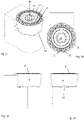
Figs. 1-3 ,7 and 8 which show aturning insert 1. The turninginsert 1 comprises atop surface 2 comprising a rake surface and an oppositebottom surface 3 functioning as a seating surface. A reference plane RP extends mid-way between the top andbottom surfaces bottom surfaces side surface 4 connects thetop surface 2 and thebottom surface 3. Acutting edge 5 is adjacent to thetop surface 2 and theside surface 4. Thecutting edge 5 is circular and concentric in relation to a center axis A1. A throughhole 36 for a screw extends between the top andbottom surfaces top surface 2 comprises a set offirst protrusions 6. - As can be seen in
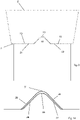
Figs. 5 and 6 , a greatest distance from the reference plane RP to thefirst protrusions 6 is greater than a distance from the reference plane RP to thecutting edge 5. - As can best be seen in e.g.
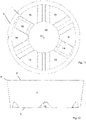
Fig. 8 , thebottom surface 3 comprises a set ofradial grooves 10 and a set offlat surfaces 19. The flat surfaces 19, arranged to function as support surfaces or contact surfaces, extend in a plane parallel to the reference plane RP. - In a top view as in
Fig. 3 , eachfirst protrusion 6 is symmetrical in relation to a line extending between the center axis A1 and a mid-point 45 of thefirst protrusion 6. Thefirst protrusions 6 are elongated in a direction parallel to or substantially parallel to theadjacent cutting edge 5. - The number of
first protrusions 6 is a multiple of the number ofradial grooves 10. - As can be seen in
Fig. 4 , adistance 41 between adjacentfirst protrusions 6 is smaller than alength 42 of afirst protrusion 6. - As seen in
Fig. 5 , eachfirst protrusion 6 is convex in a radial cross section. - The
first protrusions 6 are evenly distributed around the center axis A1, and are located at constant distance from the center axis A1. - As can be seen in
Fig. 3 , a radial angle α1 for afirst protrusion 6 is greater than a radial angle α2 of asecond protrusion 7, where said angles are measured between radial lines intersecting end points of therespective protrusion second protrusions first protrusions 6 and thesecond protrusions 7 exceeds 360°. - The first and the
second protrusions - As can be seen in e.g.
Fig. 3 thetop surface 2 of the turninginsert 1 is mirror symmetrical in relation to a plane comprising the center axis A1. The number offirst protrusions 6 is equal to the number ofsecond protrusions 7. Thefirst protrusions 6 are identical. Thesecond protrusions 7 are identical. - In a top view the
first protrusions 6 are oval shaped or substantially oval shaped. Said oval is in a top view elongated in a direction perpendicular to a radius intersecting a mid-point of the respective first protrusion, where said radius intersects the center axis. In other words, alength 42 of afirst protrusion 6 is greater than awidth 43 of afirst protrusion 6, where saidwidth 43 is measured radially in a top view and where said length is measured perpendicular to saidwidth 43, as seen inFig. 4 . - The
top surface 2 comprises a set ofsecond protrusions 7. As can be seen in e.g.Fig. 3 , a greatest distance from thecutting edge 5 to thefirst protrusions 6 is smaller than a greatest distance from thecutting edge 5 to thesecond protrusions 7. In other words, thefirst protrusions 6 are closer to thecutting edge 5, while thesecond protrusions 7 are closer to the center axis A1. As can be seen inFigs. 5 and 6 , thetop surface 2 slopes downwards from thecutting edge 5. - As seen in
Figs. 5 and 6 , a distance from the reference plane to thefirst protrusions 6 is smaller than a distance from the reference plane to thesecond protrusions 7. As seen in e.g.Fig. 5 , thefirst protrusion 6 comprises afirst surface 8 facing thecutting edge 5. As seen in e.g.Fig. 6 , thesecond protrusions 7 comprises asecond surface 9 facing thecutting edge 5. A greatest angle e1 of thefirst surface 8 in relation to the reference plane RP is smaller than a greatest angle e2 of thesecond surface 9 in relation to the reference plane RP. - The
first protrusions 6 are smaller in width, i.e. radially, than the width of thesecond protrusions 7 when seen in a top view. - The
first protrusions 6 are at a constant distance or substantially constant distance from the center axis A1. - The
second protrusions 7 are at a constant distance or substantially constant distance from the center axis A1. - The
second protrusions 7 extend radially from a circular or substantiallycircular ring 11, i.e. a ring-shaped protrusion, concentric with the center axis A1. Thefirst protrusions 6 are spaced apart from saidcircular ring 11. - The
radial grooves 10 are aligned with mid-points of first orsecond protrusions -
Figs. 25-28 show aturning tool 13 comprising atool body 14 and the above described turninginsert 1. Thetool body 14 is shown in detail inFigs. 21-24 . Theturning tool 13 comprises aninsert seat 15. Theinsert seat 15 comprises abottom surface 16 and arear surface 17. The turninginsert 1 is mounted in theinsert seat 15. Thebottom surface 16 of theinsert seat 15 comprises afirst ridge 18. - The
side surface 4 of the turninginsert 1 is in contact with therear surface 17 of theinsert seat 15, - The
first ridge 18 is inside one of theradial grooves 10 formed in thebottom surface 3 of the turninginsert 1. - The grooves and the ridge are arranged such that a small rotation, i.e. between 0° and 1°, even more preferably between 0° and 0.5°, of the turning insert around the center axis thereof is possible. The grooves and the ridge are arranged such that a rotation above 1°, preferably above 0.5°, is prevented.
- The
bottom surface 16 of theinsert seat 15 comprises support surfaces 21, 32 extending in a common plane. The flat surfaces 19 of the turninginsert 1 is in contact with the support surfaces 21, 32. - The turning
insert 1 is mounted in theinsert seat 15 by means of a screw (not shown). - As seen in
Figs. 9 and 10 , thefirst ridge 18 is smaller than one of theradial grooves 10 when seen in a cross-section perpendicular to the main extension of said one of theradial grooves 10. Saidfirst ridge 18 is inside or contained within said one of theradial grooves 10. - A
hole 36 for the screw is connecting the top andbottom surfaces insert 1. A threadedhole 22 for said screw intersects thebottom surface 16 of theinsert seat 15. - The screw preferably comprises a screw head and an external thread. A through
hole 36 for the screw is connecting the top andbottom surfaces insert 1. Thebottom surface 16 of theinsert seat 15 comprises a threadedhole 22 for the screw. The screw is at least partly located inside saidhole 36 formed in the insert and at least partly inside said threadedhole 22. - The
radial grooves 10 intersect thehole 36 formed in theturning insert 1. Theradial grooves 10 extend radially between thehole 36 and theside surface 4. - The
bottom surface 16 of theinsert seat 15 comprisesseat grooves 23. Thefirst ridge 18 is formed between theseat grooves 23. Thefirst ridge 18 and theseat grooves 23 are at least partially located on opposite sides in relation to a plane comprising the support surfaces 21, 32. - The
bottom surface 16 of theinsert seat 15 comprises asecond ridge 24. Thefirst ridge 18 and thesecond ridge 24 are aligned in a top view as seen in e.g.Fig. 14 . The first andsecond ridges hole 22 formed in thebottom surface 16 of theinsert seat 15. Thefirst ridge 18 is longer than thesecond ridge 24 when seen in a top view. Thefirst ridge 18 and thesecond ridge 24 are separated by 180° in a top view. The Thefirst ridge 18 and thesecond ridge 24 are aligned with the longitudinal axis A2 of theturning tool 13, or aligned with a line parallel to said longitudinal axis A2, when seen in a top view. - The
tool body 14 comprises a rearend coupling portion 25 suitable to be connected to a machine interface (not shown) of a CNC-lathe (not shown). Thecoupling portion 25 extends along a longitudinal axis A2 of theturning tool 13. The first andsecond ridges turning tool 13. - The
first ridge 18 has a main extension thereof along or parallel to the longitudinal axis A2 of theturning tool 13 when seen in a top view. - The center axis A1 of the turning
insert 1 is perpendicular or substantially perpendicular to the longitudinal axis A2 of theturning tool 13. - The
first ridge 18, thesecond ridge 24 and theradial grooves 10 formed in thebottom surface 3 of the turninginsert 1 have corresponding or substantially corresponding shapes in cross sections, as seen inFigs. 9 and 10 . - The number of
ridges bottom surface 16 of theinsert seat 15 is smaller than the number ofradial grooves 10 formed in thebottom surface 3 of the turninginsert 1. - As seen in
Figs. 9 and 10 , thefirst ridge 18 comprises planar ridge side surfaces 26, 27 connected by aridge crest 28. The ridge side surfaces 26, 27 form an angle of 70 - 110° in relation to each other. Eachradial groove 10 comprises radial groove side surfaces 29, 30 connected by aradial groove root 31. The radial groove side surfaces 29, 30 form an angle of 70 - 110° in relation to each other. Eachradial groove 10 is uniform or substantially uniform in cross sections along the length of the radial groove, where the length is in a radial direction. In a corresponding manner, the first andsecond ridges - A gap is formed at least between one of the pair of adjacent ridge side- and radial groove side surfaces 26, 29, 27, 30. In
Fig. 10 , a gap is formed between both of said adjacent pairs of side surfaces 26, 29, 27, 30. A gap is always formed between theridge crest 28 and theradial groove root 31. - The
bottom surface 16 of theinsert seat 15 comprises two support surfaces 21, 32 located in a common plane. In a top view as seen in e.g.Fig. 14 , an area of the support surfaces 21, 32 are greater than an area of the ridge orridges - As seen in e.g. 16, the
rear surface 17 of theinsert seat 15 comprises two spaced apart rear contact surfaces 33, 34. The rear contact surfaces 33, 34 are separated by arecess 35. - The
tool body 14 may comprise theinsert seat 15 as seen inFigs. 21-24 . In such a case, thebottom surface 3 and theside surface 4 of the turninginsert 1 is partly in contact with thetool body 14, as seen inFigs. 25-28 . Alternatively, the turningtool 13 may comprise ashim 37, such as theshim 37 shown inFigs. 43-46 . In such case, as seen inFigs. 33-36 , thebottom surface 3 of the turninginsert 1 is in contact with theshim 37, while theside surface 4 of the turninginsert 1 is in contact with thetool body 14. -
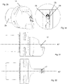
Figs. 41 and 42 schematically show a method to machine ametal work piece 38 by means of any of the above described turningtools 13. Themetal work piece 38 rotates in one direction around a rotational axis A3 thereof. The first ridge is oriented perpendicular to the rotational axis A3 of themetal work piece 38. Cutting themetal work piece 38 is made by first moving theturning tool 13 in afirst direction 39 parallel to the rotational axis A3 of themetal work piece 38, and thereafter cutting themetal work piece 38 by moving theturning tool 13 in asecond direction 40 parallel to the rotational axis A3 of themetal work piece 38, where thesecond direction 40 is opposite to thefirst direction 39. - In
Fig. 41 , oneridge surface 27 as seen inFig. 10 is in contact with one radialgroove side surface 30, while inFig. 42 , oneother ridge surface 26 is in contact with one other radialgroove side surface 29. Thus, the turning insert have made a rotational movement of a predetermined angle around the center axis thereof when comparing the end of the pass shown inFig. 41 and the end of the pass shown inFig. 42 . In other words, inFig. 41 , there is at least a partial gap between theother ridge surface 26 and the one other radialgroove side surface 29. In a corresponding manner, inFig. 42 there is at least a partial gap between said oneridge surface 27 and said one radialgroove side surface 30. In other words, theridge crest 28 seen inFig. 10 forms an angle in a top view in relation to theradial groove root 31. This can be understood fromFig. 11 .
Claims (12)
- A turning insert (1) comprisinga top surface (2),an opposite bottom surface (3),a reference plane (RP) between the top and bottom surfaces (2, 3),a center axis (A1) intersecting the top and bottom surfaces (2, 3),a side surface (4) connecting the top surface (2) and the bottom surface (3),a cutting edge (5) adjacent to the top surface (2) and the side surface (4),the cutting edge (5) being circular and concentric in relation to the center axis (A1),wherein the bottom surface (3) comprises a set of radial grooves (10),wherein the bottom surface (3) comprises a set of flat surfaces (19), wherein the flat surfaces (19) extend in a plane parallel to the reference plane (RP),wherein the top surface (2) comprises a set of first protrusions (6), wherein a greatest distance from the reference plane (RP) to the first protrusions (6) is greater than a distance from the reference plane (RP) to the cutting edge (5),wherein the number of first protrusions (6) is a multiple of the number of radial grooves (10),wherein the first protrusion (6) comprises a first surface (8) facing the cutting edge (5)characterized in thatin a top view each first protrusion (6) is symmetrical in relation to a line extending between the center axis (A1) and a mid-point (45) of the first protrusion (6),wherein the first protrusions (6) are elongated in a direction parallel to the adjacent cutting edge (5),wherein the top surface (2) comprises a set of second protrusions (7),wherein a greatest distance from the cutting edge (5) to the first protrusions (6) is smaller than a greatest distance from the cutting edge (5) to the second protrusions (7),wherein a distance from the reference plane (RP) to the first protrusions (6) is smaller than a distance from the reference plane (RP) to the second protrusions (7),wherein the second protrusions (7) comprises a second surface (9) facing the cutting edge (5), andwherein a greatest angle (e1) of the first surface (8) in relation to the reference plane (RP) is smaller than a greatest angle (e2) of the second surface (9) in relation to the reference plane (RP).
- A turning insert (1) according to any of the preceding claims, wherein a distance between adjacent first protrusions (6) is smaller than a length of a first protrusion (6).
- A turning insert (1) according to any of the preceding claims, wherein each first protrusion (6) is convex in a radial cross section and in a cross-section perpendicular to the radial cross section.
- A turning insert (1) according to any of the preceding claims, wherein the first protrusions (6) are evenly distributed around the center axis (A1).
- A turning insert (1) according to any of the preceding claims, wherein the top surface (2) is mirror symmetrical in relation to a plane comprising and parallel to the center axis (A1)
- A turning insert (1) according to any of the preceding claims, wherein in a top view the first protrusions (6) are oval shaped or substantially oval shaped.
- A turning insert (1) according to any of the preceding claims,wherein the number of first protrusions (6) is equal to the number of second protrusions (7),wherein the first protrusions (6) are identical or substantially identical,wherein the second protrusions (7) are identical or substantially identical,wherein the first protrusions (6) are smaller than the second protrusions (7) when seen in a top view,wherein the first protrusions (6) are at a constant distance or substantially constant distance from the center axis (A1),wherein the second protrusions (7) are at a constant distance or substantially constant distance from the center axis (A1),wherein the second protrusions (7) extend radially from a circular or substantially circular ring (11) concentric with the center axis (A1).
- A turning insert (1) according to any of the preceding claims,wherein the first and second protrusions (6, 7) radially overlap when seen in a top view,wherein the first and the second protrusions (6, 7), respectively, are uniformly distributed around the center axis (A1).
- A turning insert (1) according to any of the preceding claims, wherein the radial grooves (10) are aligned with mid-points of first or second protrusions (6, 7).
- A turning tool (13) comprising a tool body (14) and a turning insert (1) according to any of the preceding claims,wherein the turning tool (13) comprises an insert seat (15),wherein the insert seat (15) comprises a bottom surface (16) and a rear surface (17),wherein the turning insert (1) is mounted in the insert seat (15), wherein the bottom surface (16) of the insert seat (15) comprises a first ridge (18),wherein the side surface (4) of the turning insert (1) is in contact with the rear surface (17) of the insert seat (15),wherein the first ridge (18) is inside one of the radial grooves (10) formed in the bottom surface (3) of the turning insert (1).
- A turning tool (13) according to claim 10,wherein the bottom surface (16) of the insert seat (15) comprises one or more support surfaces (21, 32),wherein the support surfaces (21, 32) extends in a common plane, wherein the flat surfaces (19) of the turning insert (1) is in contact with the support surfaces (21, 32).
- A method to machine a metal work piece (38), comprising the steps of:providing a metal work piece (38),providing a turning tool according to claim 11,rotating the metal work piece (38) around a rotational axis (A3) thereof,arranging the turning tool (13) such that the first ridge (18) is oriented perpendicular to the rotational axis (A3) of the metal work piece (38),cutting the metal work piece (38) by moving the turning tool (13) in a first direction parallel to the rotational axis (A3) of the metal work piece (38),and cutting the metal work piece (38) by moving the turning tool (13) in a second direction parallel to the rotational axis (A3) of the metal work piece (38), where the second direction is opposite to the first direction.
Priority Applications (4)
| Application Number | Priority Date | Filing Date | Title |
|---|---|---|---|
| EP19174816.9A EP3738698B1 (en) | 2019-05-16 | 2019-05-16 | Turning insert for metal cutting, a cutting tool and a method to machine a metal workpiece |
| CN202080030470.6A CN113710396B (en) | 2019-05-16 | 2020-02-06 | Turning insert for metal cutting |
| US17/611,518 US12053827B2 (en) | 2019-05-16 | 2020-02-06 | Turning insert for metal cutting |
| PCT/EP2020/052926 WO2020228999A1 (en) | 2019-05-16 | 2020-02-06 | Turning insert for metal cutting |
Applications Claiming Priority (1)
| Application Number | Priority Date | Filing Date | Title |
|---|---|---|---|
| EP19174816.9A EP3738698B1 (en) | 2019-05-16 | 2019-05-16 | Turning insert for metal cutting, a cutting tool and a method to machine a metal workpiece |
Publications (2)
| Publication Number | Publication Date |
|---|---|
| EP3738698A1 EP3738698A1 (en) | 2020-11-18 |
| EP3738698B1 true EP3738698B1 (en) | 2022-11-02 |
Family
ID=66589276
Family Applications (1)
| Application Number | Title | Priority Date | Filing Date |
|---|---|---|---|
| EP19174816.9A Active EP3738698B1 (en) | 2019-05-16 | 2019-05-16 | Turning insert for metal cutting, a cutting tool and a method to machine a metal workpiece |
Country Status (4)
| Country | Link |
|---|---|
| US (1) | US12053827B2 (en) |
| EP (1) | EP3738698B1 (en) |
| CN (1) | CN113710396B (en) |
| WO (1) | WO2020228999A1 (en) |
Families Citing this family (5)
| Publication number | Priority date | Publication date | Assignee | Title |
|---|---|---|---|---|
| EP3738697B1 (en) * | 2019-05-16 | 2023-02-22 | AB Sandvik Coromant | Turning tool for metal cutting |
| USD1040198S1 (en) * | 2021-05-17 | 2024-08-27 | Seco Tools Ab | Cutting insert |
| USD1040875S1 (en) * | 2021-05-17 | 2024-09-03 | Seco Tools Ab | Cutting insert |
| JP1742087S (en) * | 2021-10-01 | 2023-04-17 | cutting insert | |
| JP1742086S (en) * | 2021-10-01 | 2023-04-17 | cutting insert |
Family Cites Families (49)
| Publication number | Priority date | Publication date | Assignee | Title |
|---|---|---|---|---|
| JP2666935B2 (en) * | 1987-10-30 | 1997-10-22 | 京セラ株式会社 | Cutting tip |
| SE466689B (en) * | 1990-07-19 | 1992-03-23 | Sandvik Ab | CUTS FOR PROFILE AND SAVINGS WARNING |
| US5236288A (en) * | 1991-11-08 | 1993-08-17 | National Carbide Outlet, Inc. | Cutter with positively locked round inserts |
| DE4244316C2 (en) * | 1992-12-28 | 2002-08-29 | Widia Gmbh | cutting tool |
| US5478175A (en) * | 1993-08-24 | 1995-12-26 | Greenleaf Corporation | Cutting insert assembly |
| US5924826A (en) * | 1994-04-27 | 1999-07-20 | Sandvik Ab | Cutting insert mounted on holder by rib-and-groove coupling |
| DE4430171C2 (en) * | 1994-08-25 | 1996-08-14 | Walter Ag | Form-locked insert |
| SE509363C2 (en) * | 1995-09-25 | 1999-01-18 | Sandvik Ab | Fixing device removes cutting plates and cutting plate intended for such device |
| GB9520436D0 (en) * | 1995-10-06 | 1995-12-06 | Sandvik Ab | Cutting insert |
| IL119841A (en) * | 1996-12-16 | 2000-02-29 | Iscar Ltd | Cutting inserts |
| SE511390C2 (en) * | 1997-03-05 | 1999-09-20 | Sandvik Ab | Device for clamping cutting plates for cutting metal machining |
| US6599061B1 (en) * | 2000-08-17 | 2003-07-29 | Kennametal Inc. | Cutting insert with radially aligned chip forming grooves |
| SE521579C2 (en) * | 2002-03-21 | 2003-11-11 | Sandvik Ab | Tools and cutting tools for chip separating machining |
| SE525496C2 (en) * | 2002-03-21 | 2005-03-01 | Sandvik Ab | Tools for chip separator machining as well as rotary cutter for such tools |
| JP3952853B2 (en) * | 2002-05-24 | 2007-08-01 | 三菱マテリアル株式会社 | Throwaway tip |
| SE526539C2 (en) * | 2002-05-28 | 2005-10-04 | Sandvik Intellectual Property | Chip separation machining tool where the cutting position has flexible portions. |
| US6796752B2 (en) * | 2002-06-19 | 2004-09-28 | Manchester Tool Company | Cutting insert |
| KR100625900B1 (en) * | 2002-06-25 | 2006-09-20 | 엔지케이 스파크 플러그 캄파니 리미티드 | Insert, holder and cutting tool |
| SE525913C2 (en) * | 2002-12-20 | 2005-05-24 | Seco Tools Ab | Cutter, tool and method of mounting the insert where the insert can be oriented in the desired position |
| SE526255C2 (en) * | 2003-03-14 | 2005-08-09 | Sandvik Intellectual Property | Tools and indexable inserts for fine turning of rotationally symmetrical grooves in workpieces |
| EP1635976B1 (en) * | 2003-03-17 | 2010-09-01 | Seco Tools AB | Indexable insert with corners with different radii |
| US7156006B2 (en) * | 2003-09-02 | 2007-01-02 | Kennametal Inc. | Method and assembly for rotating a cutting insert during a turning operation and inserts used therein |
| SE526399C2 (en) * | 2004-01-30 | 2005-09-06 | Sandvik Intellectual Property | Cutting tools and parts therewith with coupling surfaces with grooves and their manufacturing process |
| US7325471B2 (en) * | 2004-09-07 | 2008-02-05 | Kennametal Inc. | Toolholder and cutting insert for a toolholder assembly |
| SE527613C2 (en) * | 2004-10-15 | 2006-04-25 | Seco Tools Ab | Tool for cutting machining with a base plate with recesses |
| AT8433U1 (en) * | 2005-03-11 | 2006-08-15 | Ceratizit Austria Gmbh | TURNING CUTTING BOARD |
| SE528751C2 (en) * | 2005-06-27 | 2007-02-06 | Sandvik Intellectual Property | Turning tools and indexable turning tools, as well as additives for such turning tools |
| US7607867B2 (en) | 2006-12-15 | 2009-10-27 | Sandvik Intellectual Property Ab | Tooling insert with mating surface |
| US7458753B1 (en) * | 2007-06-25 | 2008-12-02 | Kennametal Inc. | Round cutting insert with chip control feature |
| RU2492970C1 (en) * | 2009-06-24 | 2013-09-20 | Тунгалой Корпорейшн | Cutting plate |
| IL199936A0 (en) * | 2009-07-19 | 2010-04-15 | Iscar Ltd | Rotary cutting tool and cutting insert therefor |
| US8573903B2 (en) * | 2009-11-03 | 2013-11-05 | Kennametal Inc. | Round cutting insert with anti-rotation feature |
| US8388274B2 (en) * | 2010-01-06 | 2013-03-05 | Kennametal Inc. | Round cutting insert with asymmetric chipbreaker feature |
| CN103842119B (en) * | 2011-10-07 | 2016-12-14 | 株式会社钨钛合金 | Bit replacing formula cutting element |
| US8858130B2 (en) * | 2012-04-24 | 2014-10-14 | Kennametal Inc. | Indexable circular cutting insert |
| US9011049B2 (en) * | 2012-09-25 | 2015-04-21 | Kennametal Inc. | Double-sided cutting inserts with anti-rotation features |
| DE102013113235B4 (en) * | 2012-12-04 | 2021-02-25 | Kennametal India Ltd. | Cutting insert with curved edges |
| US9180533B2 (en) * | 2013-02-07 | 2015-11-10 | Kennametal Inc. | Round cutting insert with serrated topography |
| US10406608B2 (en) * | 2015-01-19 | 2019-09-10 | Kennametal Inc. | Cutting insert and pocket with uninterrupted and continuous seating surface perimeter |
| EP3153257B1 (en) | 2015-10-09 | 2019-07-17 | Sandvik Intellectual Property AB | Method to machine a metal work piece by turning |
| EP3153260B1 (en) * | 2015-10-09 | 2018-05-23 | Sandvik Intellectual Property AB | Turning insert and method |
| US10195673B2 (en) * | 2015-12-11 | 2019-02-05 | Kennametal Inc. | Ceramic cutting insert and method of making same |
| US10183333B2 (en) * | 2016-02-03 | 2019-01-22 | Iscar, Ltd. | Circular cutting insert having non-circular peripheral edge |
| EP3260225B1 (en) * | 2016-06-20 | 2022-11-30 | Sandvik Intellectual Property AB | Turning insert |
| WO2018221300A1 (en) * | 2017-05-29 | 2018-12-06 | 京セラ株式会社 | Cutting insert, cutting tool provided with same, and method for manufacturing cut workpiece |
| EP3476508A1 (en) * | 2017-10-31 | 2019-05-01 | Sandvik Intellectual Property AB | Turning insert |
| PL3501701T3 (en) * | 2017-12-22 | 2021-01-11 | Ceratizit Austria Gesellschaft M.B.H. | Tool system and method for turning |
| KR102262037B1 (en) * | 2019-12-27 | 2021-06-08 | 한국야금 주식회사 | Cutting insert and Tool mounted withthere |
| US11786982B2 (en) * | 2021-04-26 | 2023-10-17 | Kennametal Inc. | Cutting tool comprising toolholder and round cutting insert and method for repositioning the round cutting insert in a pocket of the toolholder |
-
2019
- 2019-05-16 EP EP19174816.9A patent/EP3738698B1/en active Active
-
2020
- 2020-02-06 US US17/611,518 patent/US12053827B2/en active Active
- 2020-02-06 WO PCT/EP2020/052926 patent/WO2020228999A1/en active Application Filing
- 2020-02-06 CN CN202080030470.6A patent/CN113710396B/en active Active
Also Published As
| Publication number | Publication date |
|---|---|
| WO2020228999A1 (en) | 2020-11-19 |
| US20220234115A1 (en) | 2022-07-28 |
| US12053827B2 (en) | 2024-08-06 |
| EP3738698A1 (en) | 2020-11-18 |
| CN113710396B (en) | 2024-04-26 |
| CN113710396A (en) | 2021-11-26 |
Similar Documents
| Publication | Publication Date | Title |
|---|---|---|
| EP3738698B1 (en) | Turning insert for metal cutting, a cutting tool and a method to machine a metal workpiece | |
| RU2370349C2 (en) | Cutting plate for face milling and milling tool | |
| KR101618393B1 (en) | Cutting inset and tool having cutting inserts | |
| JP5906976B2 (en) | Cutting insert and cutting edge changeable cutting tool | |
| US6655881B2 (en) | Throw-away tip | |
| US6802676B2 (en) | Milling insert | |
| JP7049263B2 (en) | Face grooving tool for metal cutting | |
| EP3260225B1 (en) | Turning insert | |
| EP3677368B1 (en) | Cutting insert and indexable ball end mil | |
| JP5938868B2 (en) | Cutting insert and cutting edge changeable cutting tool | |
| US11052465B2 (en) | Turning insert | |
| JP5580239B2 (en) | Milling tools | |
| CN113710395B (en) | Turning tool for metal cutting | |
| JP7417137B2 (en) | Cutting inserts and indexable ball end mills | |
| EP4091749A1 (en) | A metal cutting turning tool | |
| EP4389326A1 (en) | Turning tool and a cutting insert therefor | |
| CN116887938A (en) | Cutting insert and indexable insert cutting tool | |
| JP2020127992A (en) | Cutting insert, cutting edge replaceable type end mill and end mill main body |
Legal Events
| Date | Code | Title | Description |
|---|---|---|---|
| PUAI | Public reference made under article 153(3) epc to a published international application that has entered the european phase |
Free format text: ORIGINAL CODE: 0009012 |
|
| STAA | Information on the status of an ep patent application or granted ep patent |
Free format text: STATUS: THE APPLICATION HAS BEEN PUBLISHED |
|
| AK | Designated contracting states |
Kind code of ref document: A1 Designated state(s): AL AT BE BG CH CY CZ DE DK EE ES FI FR GB GR HR HU IE IS IT LI LT LU LV MC MK MT NL NO PL PT RO RS SE SI SK SM TR |
|
| AX | Request for extension of the european patent |
Extension state: BA ME |
|
| STAA | Information on the status of an ep patent application or granted ep patent |
Free format text: STATUS: REQUEST FOR EXAMINATION WAS MADE |
|
| 17P | Request for examination filed |
Effective date: 20210518 |
|
| RBV | Designated contracting states (corrected) |
Designated state(s): AL AT BE BG CH CY CZ DE DK EE ES FI FR GB GR HR HU IE IS IT LI LT LU LV MC MK MT NL NO PL PT RO RS SE SI SK SM TR |
|
| GRAP | Despatch of communication of intention to grant a patent |
Free format text: ORIGINAL CODE: EPIDOSNIGR1 |
|
| STAA | Information on the status of an ep patent application or granted ep patent |
Free format text: STATUS: GRANT OF PATENT IS INTENDED |
|
| INTG | Intention to grant announced |
Effective date: 20220614 |
|
| GRAS | Grant fee paid |
Free format text: ORIGINAL CODE: EPIDOSNIGR3 |
|
| GRAA | (expected) grant |
Free format text: ORIGINAL CODE: 0009210 |
|
| STAA | Information on the status of an ep patent application or granted ep patent |
Free format text: STATUS: THE PATENT HAS BEEN GRANTED |
|
| AK | Designated contracting states |
Kind code of ref document: B1 Designated state(s): AL AT BE BG CH CY CZ DE DK EE ES FI FR GB GR HR HU IE IS IT LI LT LU LV MC MK MT NL NO PL PT RO RS SE SI SK SM TR |
|
| REG | Reference to a national code |
Ref country code: GB Ref legal event code: FG4D |
|
| REG | Reference to a national code |
Ref country code: CH Ref legal event code: EP Ref country code: AT Ref legal event code: REF Ref document number: 1528400 Country of ref document: AT Kind code of ref document: T Effective date: 20221115 |
|
| REG | Reference to a national code |
Ref country code: DE Ref legal event code: R096 Ref document number: 602019021311 Country of ref document: DE |
|
| REG | Reference to a national code |
Ref country code: IE Ref legal event code: FG4D |
|
| REG | Reference to a national code |
Ref country code: LT Ref legal event code: MG9D |
|
| REG | Reference to a national code |
Ref country code: NL Ref legal event code: MP Effective date: 20221102 |
|
| REG | Reference to a national code |
Ref country code: AT Ref legal event code: MK05 Ref document number: 1528400 Country of ref document: AT Kind code of ref document: T Effective date: 20221102 |
|
| PG25 | Lapsed in a contracting state [announced via postgrant information from national office to epo] |
Ref country code: SE Free format text: LAPSE BECAUSE OF FAILURE TO SUBMIT A TRANSLATION OF THE DESCRIPTION OR TO PAY THE FEE WITHIN THE PRESCRIBED TIME-LIMIT Effective date: 20221102 Ref country code: PT Free format text: LAPSE BECAUSE OF FAILURE TO SUBMIT A TRANSLATION OF THE DESCRIPTION OR TO PAY THE FEE WITHIN THE PRESCRIBED TIME-LIMIT Effective date: 20230302 Ref country code: NO Free format text: LAPSE BECAUSE OF FAILURE TO SUBMIT A TRANSLATION OF THE DESCRIPTION OR TO PAY THE FEE WITHIN THE PRESCRIBED TIME-LIMIT Effective date: 20230202 Ref country code: LT Free format text: LAPSE BECAUSE OF FAILURE TO SUBMIT A TRANSLATION OF THE DESCRIPTION OR TO PAY THE FEE WITHIN THE PRESCRIBED TIME-LIMIT Effective date: 20221102 Ref country code: FI Free format text: LAPSE BECAUSE OF FAILURE TO SUBMIT A TRANSLATION OF THE DESCRIPTION OR TO PAY THE FEE WITHIN THE PRESCRIBED TIME-LIMIT Effective date: 20221102 Ref country code: ES Free format text: LAPSE BECAUSE OF FAILURE TO SUBMIT A TRANSLATION OF THE DESCRIPTION OR TO PAY THE FEE WITHIN THE PRESCRIBED TIME-LIMIT Effective date: 20221102 Ref country code: AT Free format text: LAPSE BECAUSE OF FAILURE TO SUBMIT A TRANSLATION OF THE DESCRIPTION OR TO PAY THE FEE WITHIN THE PRESCRIBED TIME-LIMIT Effective date: 20221102 |
|
| PG25 | Lapsed in a contracting state [announced via postgrant information from national office to epo] |
Ref country code: RS Free format text: LAPSE BECAUSE OF FAILURE TO SUBMIT A TRANSLATION OF THE DESCRIPTION OR TO PAY THE FEE WITHIN THE PRESCRIBED TIME-LIMIT Effective date: 20221102 Ref country code: PL Free format text: LAPSE BECAUSE OF FAILURE TO SUBMIT A TRANSLATION OF THE DESCRIPTION OR TO PAY THE FEE WITHIN THE PRESCRIBED TIME-LIMIT Effective date: 20221102 Ref country code: LV Free format text: LAPSE BECAUSE OF FAILURE TO SUBMIT A TRANSLATION OF THE DESCRIPTION OR TO PAY THE FEE WITHIN THE PRESCRIBED TIME-LIMIT Effective date: 20221102 Ref country code: IS Free format text: LAPSE BECAUSE OF FAILURE TO SUBMIT A TRANSLATION OF THE DESCRIPTION OR TO PAY THE FEE WITHIN THE PRESCRIBED TIME-LIMIT Effective date: 20230302 Ref country code: HR Free format text: LAPSE BECAUSE OF FAILURE TO SUBMIT A TRANSLATION OF THE DESCRIPTION OR TO PAY THE FEE WITHIN THE PRESCRIBED TIME-LIMIT Effective date: 20221102 Ref country code: GR Free format text: LAPSE BECAUSE OF FAILURE TO SUBMIT A TRANSLATION OF THE DESCRIPTION OR TO PAY THE FEE WITHIN THE PRESCRIBED TIME-LIMIT Effective date: 20230203 |
|
| PG25 | Lapsed in a contracting state [announced via postgrant information from national office to epo] |
Ref country code: NL Free format text: LAPSE BECAUSE OF FAILURE TO SUBMIT A TRANSLATION OF THE DESCRIPTION OR TO PAY THE FEE WITHIN THE PRESCRIBED TIME-LIMIT Effective date: 20221102 |
|
| P01 | Opt-out of the competence of the unified patent court (upc) registered |
Effective date: 20230603 |
|
| PG25 | Lapsed in a contracting state [announced via postgrant information from national office to epo] |
Ref country code: SM Free format text: LAPSE BECAUSE OF FAILURE TO SUBMIT A TRANSLATION OF THE DESCRIPTION OR TO PAY THE FEE WITHIN THE PRESCRIBED TIME-LIMIT Effective date: 20221102 Ref country code: RO Free format text: LAPSE BECAUSE OF FAILURE TO SUBMIT A TRANSLATION OF THE DESCRIPTION OR TO PAY THE FEE WITHIN THE PRESCRIBED TIME-LIMIT Effective date: 20221102 Ref country code: EE Free format text: LAPSE BECAUSE OF FAILURE TO SUBMIT A TRANSLATION OF THE DESCRIPTION OR TO PAY THE FEE WITHIN THE PRESCRIBED TIME-LIMIT Effective date: 20221102 Ref country code: DK Free format text: LAPSE BECAUSE OF FAILURE TO SUBMIT A TRANSLATION OF THE DESCRIPTION OR TO PAY THE FEE WITHIN THE PRESCRIBED TIME-LIMIT Effective date: 20221102 Ref country code: CZ Free format text: LAPSE BECAUSE OF FAILURE TO SUBMIT A TRANSLATION OF THE DESCRIPTION OR TO PAY THE FEE WITHIN THE PRESCRIBED TIME-LIMIT Effective date: 20221102 |
|
| REG | Reference to a national code |
Ref country code: DE Ref legal event code: R097 Ref document number: 602019021311 Country of ref document: DE |
|
| PG25 | Lapsed in a contracting state [announced via postgrant information from national office to epo] |
Ref country code: SK Free format text: LAPSE BECAUSE OF FAILURE TO SUBMIT A TRANSLATION OF THE DESCRIPTION OR TO PAY THE FEE WITHIN THE PRESCRIBED TIME-LIMIT Effective date: 20221102 Ref country code: AL Free format text: LAPSE BECAUSE OF FAILURE TO SUBMIT A TRANSLATION OF THE DESCRIPTION OR TO PAY THE FEE WITHIN THE PRESCRIBED TIME-LIMIT Effective date: 20221102 |
|
| PLBE | No opposition filed within time limit |
Free format text: ORIGINAL CODE: 0009261 |
|
| STAA | Information on the status of an ep patent application or granted ep patent |
Free format text: STATUS: NO OPPOSITION FILED WITHIN TIME LIMIT |
|
| 26N | No opposition filed |
Effective date: 20230803 |
|
| PG25 | Lapsed in a contracting state [announced via postgrant information from national office to epo] |
Ref country code: SI Free format text: LAPSE BECAUSE OF FAILURE TO SUBMIT A TRANSLATION OF THE DESCRIPTION OR TO PAY THE FEE WITHIN THE PRESCRIBED TIME-LIMIT Effective date: 20221102 |
|
| REG | Reference to a national code |
Ref country code: CH Ref legal event code: PL |
|
| PG25 | Lapsed in a contracting state [announced via postgrant information from national office to epo] |
Ref country code: MC Free format text: LAPSE BECAUSE OF FAILURE TO SUBMIT A TRANSLATION OF THE DESCRIPTION OR TO PAY THE FEE WITHIN THE PRESCRIBED TIME-LIMIT Effective date: 20221102 |
|
| REG | Reference to a national code |
Ref country code: BE Ref legal event code: MM Effective date: 20230531 |
|
| PG25 | Lapsed in a contracting state [announced via postgrant information from national office to epo] |
Ref country code: MC Free format text: LAPSE BECAUSE OF FAILURE TO SUBMIT A TRANSLATION OF THE DESCRIPTION OR TO PAY THE FEE WITHIN THE PRESCRIBED TIME-LIMIT Effective date: 20221102 Ref country code: LU Free format text: LAPSE BECAUSE OF NON-PAYMENT OF DUE FEES Effective date: 20230516 Ref country code: LI Free format text: LAPSE BECAUSE OF NON-PAYMENT OF DUE FEES Effective date: 20230531 Ref country code: CH Free format text: LAPSE BECAUSE OF NON-PAYMENT OF DUE FEES Effective date: 20230531 |
|
| REG | Reference to a national code |
Ref country code: IE Ref legal event code: MM4A |
|
| PG25 | Lapsed in a contracting state [announced via postgrant information from national office to epo] |
Ref country code: IE Free format text: LAPSE BECAUSE OF NON-PAYMENT OF DUE FEES Effective date: 20230516 |
|
| PG25 | Lapsed in a contracting state [announced via postgrant information from national office to epo] |
Ref country code: IE Free format text: LAPSE BECAUSE OF NON-PAYMENT OF DUE FEES Effective date: 20230516 |
|
| PG25 | Lapsed in a contracting state [announced via postgrant information from national office to epo] |
Ref country code: BE Free format text: LAPSE BECAUSE OF NON-PAYMENT OF DUE FEES Effective date: 20230531 |
|
| PGFP | Annual fee paid to national office [announced via postgrant information from national office to epo] |
Ref country code: GB Payment date: 20240404 Year of fee payment: 6 |
|
| PGFP | Annual fee paid to national office [announced via postgrant information from national office to epo] |
Ref country code: DE Payment date: 20240403 Year of fee payment: 6 |
|
| PGFP | Annual fee paid to national office [announced via postgrant information from national office to epo] |
Ref country code: IT Payment date: 20240411 Year of fee payment: 6 Ref country code: FR Payment date: 20240422 Year of fee payment: 6 |