EP0805596A1 - Motion vector detection and band compression apparatus - Google Patents
Motion vector detection and band compression apparatus Download PDFInfo
- Publication number
- EP0805596A1 EP0805596A1 EP19970201781 EP97201781A EP0805596A1 EP 0805596 A1 EP0805596 A1 EP 0805596A1 EP 19970201781 EP19970201781 EP 19970201781 EP 97201781 A EP97201781 A EP 97201781A EP 0805596 A1 EP0805596 A1 EP 0805596A1
- Authority
- EP
- European Patent Office
- Prior art keywords
- block
- picture
- data
- circuit
- delay
- Prior art date
- Legal status (The legal status is an assumption and is not a legal conclusion. Google has not performed a legal analysis and makes no representation as to the accuracy of the status listed.)
- Withdrawn
Links
Images


Classifications
-
- H—ELECTRICITY
- H04—ELECTRIC COMMUNICATION TECHNIQUE
- H04N—PICTORIAL COMMUNICATION, e.g. TELEVISION
- H04N19/00—Methods or arrangements for coding, decoding, compressing or decompressing digital video signals
- H04N19/50—Methods or arrangements for coding, decoding, compressing or decompressing digital video signals using predictive coding
-
- H—ELECTRICITY
- H04—ELECTRIC COMMUNICATION TECHNIQUE
- H04N—PICTORIAL COMMUNICATION, e.g. TELEVISION
- H04N5/00—Details of television systems
- H04N5/14—Picture signal circuitry for video frequency region
- H04N5/144—Movement detection
- H04N5/145—Movement estimation
-
- G—PHYSICS
- G06—COMPUTING; CALCULATING OR COUNTING
- G06T—IMAGE DATA PROCESSING OR GENERATION, IN GENERAL
- G06T7/00—Image analysis
- G06T7/20—Analysis of motion
- G06T7/223—Analysis of motion using block-matching
- G06T7/231—Analysis of motion using block-matching using full search
-
- H—ELECTRICITY
- H04—ELECTRIC COMMUNICATION TECHNIQUE
- H04N—PICTORIAL COMMUNICATION, e.g. TELEVISION
- H04N11/00—Colour television systems
- H04N11/04—Colour television systems using pulse code modulation
-
- H—ELECTRICITY
- H04—ELECTRIC COMMUNICATION TECHNIQUE
- H04N—PICTORIAL COMMUNICATION, e.g. TELEVISION
- H04N19/00—Methods or arrangements for coding, decoding, compressing or decompressing digital video signals
- H04N19/42—Methods or arrangements for coding, decoding, compressing or decompressing digital video signals characterised by implementation details or hardware specially adapted for video compression or decompression, e.g. dedicated software implementation
-
- H—ELECTRICITY
- H04—ELECTRIC COMMUNICATION TECHNIQUE
- H04N—PICTORIAL COMMUNICATION, e.g. TELEVISION
- H04N19/00—Methods or arrangements for coding, decoding, compressing or decompressing digital video signals
- H04N19/50—Methods or arrangements for coding, decoding, compressing or decompressing digital video signals using predictive coding
- H04N19/503—Methods or arrangements for coding, decoding, compressing or decompressing digital video signals using predictive coding involving temporal prediction
- H04N19/51—Motion estimation or motion compensation
-
- H—ELECTRICITY
- H04—ELECTRIC COMMUNICATION TECHNIQUE
- H04N—PICTORIAL COMMUNICATION, e.g. TELEVISION
- H04N19/00—Methods or arrangements for coding, decoding, compressing or decompressing digital video signals
- H04N19/60—Methods or arrangements for coding, decoding, compressing or decompressing digital video signals using transform coding
- H04N19/61—Methods or arrangements for coding, decoding, compressing or decompressing digital video signals using transform coding in combination with predictive coding
-
- H—ELECTRICITY
- H04—ELECTRIC COMMUNICATION TECHNIQUE
- H04N—PICTORIAL COMMUNICATION, e.g. TELEVISION
- H04N19/00—Methods or arrangements for coding, decoding, compressing or decompressing digital video signals
- H04N19/90—Methods or arrangements for coding, decoding, compressing or decompressing digital video signals using coding techniques not provided for in groups H04N19/10-H04N19/85, e.g. fractals
- H04N19/96—Tree coding, e.g. quad-tree coding
-
- G—PHYSICS
- G06—COMPUTING; CALCULATING OR COUNTING
- G06T—IMAGE DATA PROCESSING OR GENERATION, IN GENERAL
- G06T2200/00—Indexing scheme for image data processing or generation, in general
- G06T2200/28—Indexing scheme for image data processing or generation, in general involving image processing hardware
-
- G—PHYSICS
- G06—COMPUTING; CALCULATING OR COUNTING
- G06T—IMAGE DATA PROCESSING OR GENERATION, IN GENERAL
- G06T2207/00—Indexing scheme for image analysis or image enhancement
- G06T2207/10—Image acquisition modality
- G06T2207/10016—Video; Image sequence
-
- G—PHYSICS
- G06—COMPUTING; CALCULATING OR COUNTING
- G06T—IMAGE DATA PROCESSING OR GENERATION, IN GENERAL
- G06T2207/00—Indexing scheme for image analysis or image enhancement
- G06T2207/20—Special algorithmic details
- G06T2207/20048—Transform domain processing
- G06T2207/20052—Discrete cosine transform [DCT]
Definitions
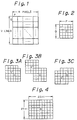
- Figures 3A to 3C of the accompanying drawings show positional relationships between such a block where a picture element C is the centre picture element and another block where a picture element C' is the centre picture element.
- the former block is from a current frame
- the latter block is from a preceding frame and matches the picture content of the block of the current frame but, due to motion, is at a position in the preceding frame with a centre picture element C'.
- Figure 3A thus represents a motion vector where the centre position of the picture has moved by +1 picture element in the horizontal direction and by +1 line in the vertical direction.
- Figure 3B represents a motion vector where the centre position of the picture has moved by +3 picture elements in the horizontal direction and by +3 lines in the vertical direction.
- Figure 3C represents a motion vector where the centre position of the picture has moved by +2 picture elements in the horizontal direction and by -1 line in the vertical direction.
- a motion vector can be obtained for each block of the current frame.
- a particular block of the current frame should be compared with various blocks in the preceding frame where C' is moved from C, which is the centre of the current frame, over ⁇ S picture elements in the horizontal direction and over ⁇ T lines in the vertical direction.
- Figure 4 of the accompanying drawings indicates that, when the position of the centre picture element C of a particular block of the current frame is R, it should be compared with (2S + 1) x (2T + 1) blocks of the preceding frame. In other words, all blocks of the preceding frame where C' is present, as shown in Figure 4, should be compared.
- some of the blocks may be omitted (that is, part of the blocks may be omitted) in detecting a motion vector.
- all positional relationships are compared over ⁇ S picture elements in the horizontal direction and ⁇ T lines in the vertical direction, some combinations of these comparisons may in fact be omitted. Nevertheless, in the following, all combinations are compared so as to simplify the description.
- Figure 6 is a conceptual block diagram of a system or structure for detecting a motion vector.
- Data a which is supplied from an input terminal 101, is picture data of a current frame.
- Data b is picture data of a just preceding frame which is delayed for one frame by a frame memory 102.
- a delay portion 103 causes the data b of the preceding frame to become data with various positional relationships as shown in Figure 3.
- the data is compared with the data a for the various positional relationships.
- a block comparison portion 104 outputs a matching ratio or degree of the picture for each deviated position.
- a determination portion 105 compares the matching ratios and outputs a most suitable deviation amount, namely a motion vector, to an output terminal 106.
- Embodiments of the invention described below seek to decrease the amount of hardware for the delay portion 103 and the block comparison portion 104, except for the determination portion 105 shown in Figure 6, and in particular seek to decrease the amount of hardware for the delay portion 103.
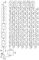
- Figures 7 and 8 show a first previously proposed system.
- Figure 7 shows portions equivalent to the frame memory 102 and the delay portion 103 shown in Figure 6.
- a block F is the frame memory 102 for delaying input data by one frame
- blocks H are delay circuits for effecting a delay of one horizontal scanning line
- small blocks without reference signs are delay circuits for effecting a delay of one picture element, namely registers
- blocks (H - 9) are delay circuits for delaying picture elements by one line less 9 picture elements.
- one line is delayed by one block (H - 9) and nine of the small blocks (registers).
- the input data a of the current frame is delayed for 3 lines and 5 picture elements by a delay circuit 107 (shown with its constituent elements surrounded by a dotted line) which becomes the centre position R of the block.
- the resultant data is supplied to an output terminal 108.
- the positions of the picture elements of the data a are the same as those of the data b.
- groups of nine stages of registers and one delay circuit (H - 9) are connected in series, and a tap C (0, 0) which has a delay of 3 lines and 5 picture elements relative to the data b has a delay of one frame relative to the centre position R.
- a motion vector is obtained, by using each tap shown in Figure 7, by performing the following process.
- data at each deviated position as shown in Figure 4 is obtained.
- the block comparison portion 104 compares each tap with R, calculates the degree of matching (of two pictures), and obtains a result for each value of (i, j). Thereafter, the determination portion 105 examines the results and selects a proper motion vector (i, j). (In a particular situation, i and j may be determined with real numbers rather than integer numbers.)
- blocks are compared for each tap C (i, j), as shown in Figure 3. From R, each picture element of the block at the centre portion shown in Figure 5 is obtained. On the other hand, from the tap C (i, j), each picture element of the block of the preceding frame which deviates by i picture elements in the horizontal direction and by j lines in the vertical direction is obtained. A subtraction circuit 109 obtains the difference between each corresponding position of the two blocks. As absolute value calculation circuit 110 calculates the absolute value (ABS) of the difference. An addition circuit 111 and a memory 112 accumulate the difference for all picture elements making up one block, namely for P x Q elements. The accumulated output is the degree of matching for (i, j).
- each picture element according to blocks in the combinations shown in Figure 3 should be obtained in succession.
- each picture element of the first line of the block is inputted to R and C (i, j).
- data for comparing the adjacent block, rather than each picture element of the next line is inputted to R and C (i, j).
- each picture element of the second line of the former block is compared.
- the memory 112 for storing H/P words or more is arranged to be an accumulation memory.
- circuits shown in Figures 7 and 8 can be realised and controlled with relative ease, their sizes are disadvantageously large.
- the frame memory 102 and the calculation circuits shown in Figure 8 are theoretically essential.
- the large number of delay circuits (H - 9) and the memories 112 having H/P words for each cumulative operation are required constructionally, not essentially.
- a second prior proposal compares blocks in such a manner that an input data sequence a is data which has been scanned for each block as shown in Figure 10B, while a data sequence b with a delay of one frame relative thereto is scanned in a wide area when the block of the data a is at the centre portion shown in Figure 5.
- the amount of data of the former data sequence differs from that of the latter data sequence.
- the number of picture elements of one block to be compared for the data sequence a is (P x Q)
- that for the data sequence b is ⁇ (2S + P) x (2T + Q) ⁇ .
- the clock frequency of the data sequence b is correspondingly increased so that the data sequence a and the data sequence b take place in accordance with timing charts shown in Figures 11A to 11C of the accompanying drawings.
- the data sequence a takes place in accordance with a timing chart as shown in Figure 11A.
- Figure 12 depicts an arrangement including a scanning transformation circuit 115 for transforming the input data sequence a into a data sequence as shown in Figure 11B.
- a scanning sequence transformation circuit 116 transforms a data sequence b from a frame memory 102' into a data sequence as shown in Figure 11C.
- the data sequence b' in which the scanning sequence has been transformed is sent to a delay portion which is composed of (2S + 1) x (2T + 1) shift register stages, which are the same as those shown in Figure 7. Thereafter, in the construction shown in Figure 8, blocks are compared.
- the (H - 9) delay circuits used in the first prior proposal ( Figure 7) become unnecessary.
- the number of words that the memory of the accumulator shown in Figure 8 requires becomes one word.
- the frame store 102' in Figure 12 has a delay (F-32) which is smaller than a frame delay by 32 picture elements.
- F-32 a delay which is smaller than a frame delay by 32 picture elements.
- the frame memory 102' sets the timing difference between R and C (0, 0) to one frame.
- the construction of the (P + 2S) x (Q + 2T) shift register stages in the second prior proposal is simpler than that of the (H - 9) delay circuit group in terms of hardware.
- the delay portion of the second prior proposal is simpler than that of the first prior proposal.
- a simple register can be used for the memory of the accumulator.
- the scanning sequence transformations P x Q and (P + 2S) x (Q + 2T) are required.
- more memories than the (H - 9) delay circuit group shown in Figure 7 are required.
- the data rate is increased by (P + 2S) x (Q + 2T)/P x Q times.
- the cumulative operation should be controlled.
- motion vectors which are detected are compensated in various picture processes.
- two frames (or fields) are compared so as to obtain a motion vector, namely a deviation between the pictures. Thereafter, one of the frames (or fields) is moved according to the amount of the deviation so as to overlap both the pictures.
- a motion picture involves not only parallel movement, but also rotation, enlargement, and reduction.
- the parallel movement component is detected and considered in the form of a motion vector.
- a motion vector detection method which has been widely used, a screen is divided into small square blocks and a motion vector is then obtained for each block. With respect to problems in detecting motion vectors and compensating them, the following items should be considered.
- the determination portion 105 comprises a remainder comparison circuit 120, to which a remainder for each deviated position after comparison of blocks is sent, and a comparison and noise removal circuit 121.
- the remainder comparison circuit 120 supplies the position and the amount of the most minimum value of the remainder, the position and amount of the second minimum value of the remainder, and the position and amount of the third minimum value of the remainder, to the comparison and noise removal circuit 121, which removes data which is determined to be noise and compares remainders.
- a determination signal representing the validity of the motion compensation and a motion vector are outputted through an AND gate 123.
- blocks are matched (in a step 124). Thereafter, the minimum value of the degree of matching is detected (in a step 125).
- the vectors at the minimum position are sorted in the order of matching ratios (in a step 126).
- the significant minimum position (where it is determined that a motion subject of the vector is present) is determined (in a step 127).
- the number of peaks of the minimum position is checked (in a step 128). If the number of peaks is 1, the motion is compensated (in a step 129). Otherwise, the motion is not compensated.
- the determination portion and motion vector compensation technique as described above are subject to the following disadvantages.
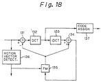
- the arrangement shown in Figure 18 includes a discrete cosine transformation (DCT) circuit 132, an inverse discrete cosine transformation (IDCT) circuit 133, and a frame memory (FM) 135 for delaying a frame.
- Input data is supplied to a motion vector detection circuit 136 and a subtraction circuit 131.
- the subtraction circuit 131 subtracts a locally decoded output of the preceding frame from the input data.
- the local decoding is performed by the IDCT circuit 133 and an addition circuit 134.
- the amount of encoded data which is generated in the DCT circuit 132 is compressed by encoding, such as Huffman encoding, carried out by means of an encoding assignment circuit 137.
- motion compensation of the frame memory 135 is accomplished by a motion vector produced by the motion vector detection circuit 136, which is disposed out of the centre loop shown in Figure 18.
- the motion vector detection circuit 136 requires another frame memory along with the frame memory 135 used for the band compression unit ( Figure 18).
- two frame memories are required for motion vector detection and band compression.
- Embodiments of the invention described below provide: a motion vector detection apparatus where a delay circuit for detecting a motion vector using a block matching scheme can be readily constructed; a motion vector detection apparatus for detecting a motion vector with easier determination and involving simpler operation than the prior proposals described above; a band compression apparatus sharing one frame memory for detecting a frame difference and a motion vector and thereby reducing hardware scale; and a band compression apparatus optimising a compression process using a diagonal conversion encoding scheme.
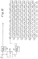
- the frame memory 102 is provided with three outputs.
- An output e has a delay ( F - 5H - 50 ) which is less than one frame by 5 H and 50 picture elements.
- An output f has a delay (F - 50) which is less than one frame by 50 picture elements.
- An output g has a delay ( F + 5H - 50 ) which is greater than one frame by 5 H minus 50 picture elements.
- Shift registers are connected to the outputs e, f, and g in such a manner that blocks are scanned. Each of the shift registers has a tap. 50 picture elements are twice as many as P x Q. A tap denoted by d in Figure 14, which is delayed by shift registers for 50 picture elements from the output f, has one frame difference from R.
- circuitry as mentioned before can be connected to each of points e', f', and g' in Figure 14, this is not necessary due to a reason which will be described later.
- the outputs f and g could be obtained by adding delay circuits to the points e' and f', respectively, though in this embodiment they are obtained from the frame memory 102.
- first data of a particular block of the current frame is present at R
- the successive 25 picture elements which are outputted are for this block.
- first data of a block of the preceding frame at the same position as the block of the current frame on the screen is present at d.
- the successive 25 picture elements are data which accord with R in screen positions.
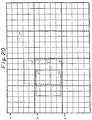
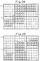
- Figure 20 shows an array for each tap shown in Figure 19.
- the tap C' which is deviated by -2 picture elements from the tap d shown in Figure 19 can be used as the tap C (-2, 0).
- the tap C' the 3 picture elements following the first picture element of the block are valid. Thereafter, the successive 2 picture elements are out of the range. Thereafter, the successive 3 picture elements are valid. Thereafter, the successive 2 picture elements are out of the range.
- the first data of the block which was at C' should be present at the tap C'.
- the first data is actually present at the tap C''.
- C'' can be used as the tap.
- C' and C'' should be selected so that C'' is selected.
- a tap which is earlier than d by j x Q taps and another tap which is earlier than d by ⁇ H x Q - (Q - j) x P ⁇ (in other words, the former tap is a tap which is later by (Q - j) x P taps than d', which has a delay from e, the delay being the same as that from f to d) are switched by the former j x P cycles and the later (Q - j) x P cycles.
- Figure 22A shows a clock signal.
- the data of the range represented by the solid lines in Figure 21 is represented as d and d' in Figures 22C and 22D, respectively.
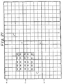
- Numbers 00 to 44 used in Figure 22 represent where each picture element of the block to be compared in Figure 21 is in the first cycle of Figure 22 when the first picture element of the block is present in R.
- 25 picture elements denoted by 00 to 44 are disposed as shown at y in Figure 22I, they cannot be compared with R by the calculation unit shown in Figure 8.
- the range represented by the solid lines in Figure 21 can be divided by the two dual lines into a lower right portion, a lower left portion, an upper right portion, and an upper left portion.
- the lower right portion consists of the picture elements 00, 01, 10, 11, 20 and 21. These picture elements are matched with the data sequence of R at the tap C'.
- the upper right portion consists of the picture elements 30, 31, 40 and 41. These picture elements are matched with R at the tap C''' according to the same consideration as the case where the block is deviated only in the vertical direction.
- the upper left portion consists of the picture elements 32, 33, 34, 42, 43 and 44.
- the picture element 32 for example, is deviated from the position 00 on the screen by -2 picture elements and -3 picture elements in the horizontal and vertical directions, respectively.
- the picture element 32 is at a position which is earlier than the position 00 by 17 stages.
- the tap C'''' which is later than the picture element 32 by 17 stages can be used.
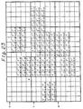
- Figure 23 shows the taps necessary in a case where blocks are deviated positively in both the horizontal and vertical directions. Since taps necessary for a case where a block is deviated positively in the horizontal direction and negatively in the vertical direction overlap with those required for other purposes, they are omitted.
- the taps in the case where the block is deviated negatively in both the horizontal and vertical directions can be used.
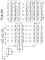
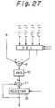
- the present embodiment can be constructed of frame memories 13 and 14 and a delay portion shown in Figure 26 and a block comparison portion shown in Figure 27.
- R can be categorised as of four types: R ++, R -+, R +- and R --.
- the output e' is not connected to taps for the first block. Thus, they are omitted. Instead, the frame memory is correspondingly delayed. In addition, with respect to the next block, 10 picture elements of the first two lines are not used. Thus, the frame memory is also delayed. Moreover, shift registers with respect to the output g are not necessary. Figure 26 does not show them. The small blocks represented by dotted lines in Figure 26 are unnecessary shift registers and they are thus omitted.
- Figure 28 shows a procedure according to the present embodiment. As opposed to the prior proposal shown in Figure 16, the distribution of the matching ratio, namely various minimum values, are not detected.
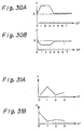
- a peak takes place at the DC component.
- Figures 32A to 32C are schematic diagrams illustrating adaptive block segmentation.
- an automobile which is a motion subject travels as shown in Figure 32A
- the neighbouring blocks are segmented locally into sub-blocks as shown in Figure 32B.
- the motion vector is recursively detected for each sub-block.
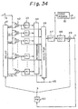
- the apparatus shown in Figure 34 includes a delay portion 41 for performing block matching as described above in the first embodiment, a subtraction circuit group 42, and a power integration (PI) circuit group 43 which comprises a multiplication circuit for squaring a value and a portion for accumulating the output thereof.
- the output of the power integration circuit group 43 is supplied to a determination portion 44.
- the determination portion 44 selects a frame difference of deviation amount with the minimum power difference. A motion vector being detected is obtained at an output terminal 45.
- a selector 46 is connected to the subtraction circuit group 42.
- An output of the selector 46 is supplied to a transformation circuit (illustratively a DCT circuit) 47.
- the output d of the transformation circuit 47 is supplied through a sign (code) assignment circuit 51 as an encoded output.
- the output d of the transformation circuit 47 is also supplied to an addition circuit 49 through an inverse transformation circuit (illustratively an IDCT circuit) 48.
- An output signal c of the addition circuit 49 is supplied to a frame memory (FM) 50.
- An output b of the frame memory 50 is supplied to the delay circuit 41 and the addition circuit 49.
- the selector 46 should be provided with a variable delay circuit.
- the delay amount of the variable delay circuit can be controlled to take account of the motion vectors being decreased.
- the band compression apparatus requires only one frame memory, whereby the size of the apparatus is reduced.
- address control delay amount control
- the selector is newly added in comparison with the prior art, it does not markedly increase the amount of hardware.
- DCT transformation circuit 47 and the inverse transformation circuit 48 are provided in the loop shown in Figure 34, it is possible to include various other processes therein. However, since such processes are incidental to the present embodiment, they are not described.
- block comparison (matching ratio calculation) circuit uses a power (square), it may be accomplished with an absolute value or another non-linear type calculation.
- known methods for decreasing motion vectors being detected can also be used in the present embodiment.
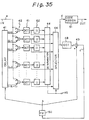
- FIG. 35 shows the construction of this embodiment, from which figure it will be seen that the transformation circuit 47 of the embodiment shown in Figure 34 is disposed in a portion for detecting a motion vector (transformation circuit group 61).
- the overall construction shown in Figure 35 is nearly the same as that shown in Figure 34. The differences between them will now be described.
- Transformation circuits making up the transformation circuit group 61 perform at least DCT.
- the transformation circuits may employ a band compression technique such as a zigzag transformation which can be used along with the DCT.
- the inverse transformation circuit 48 the inverse procedure should be performed.
- the construction shown in Figure 35 can compensate the motion vectors more suitably for band compression than that shown in Figure 34.
- the DCT circuits used in the construction shown in Figure 35 performs a linear calculation, namely an interpolation calculation (matrix calculation). Thus, the result is the same regardless of whether the frame difference has been obtained.
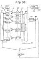
- the transformation circuit group 61 in Figure 36 is disposed at a position closer to the delay portion 41 than in Figure 35.
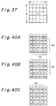
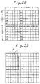
- a picture is block segmented into P picture elements by Q picture elements in the horizontal and vertical directions, respectively, as shown in Figure 37.
- a motion vector is in the range where the block is deviated by ⁇ S picture elements and ⁇ T picture elements in the horizontal and vertical directions, respectively.
- outer solid lines in Figure 38 represent the range of picture elements of the preceding frame which is used in comparing the blocks.
- a 5-line picture element group shown in Figure 40B as denoted by the reference numeral 68 overlaps with that shown in Figure 40A over 4 lines. Thus, when the 4 lines have been calculated for the block ⁇ , it is not necessary to calculate them for the block ⁇ .
- the portions designated DCT perform DCT only.
- the data mount detection circuits II are the same as the power integration circuits PI. In this case, the calculations of the data amount detection circuits II are the same as those of the power integration circuits PI because the amount of data is not changed by the DCT.
- the frequency of the data is analysed as if the data had passed through a filter bank. This is an important new feature.
- the data mount detection circuits II which are PI, can omit the calculations for such frequency components.
- the number of calculations is decreased.
- the DCT disposed at the input a knows each frequency component of the input data, it determines the DCT output and finds frequency components which it is not necessary for the circuits II to calculate, thereby decreasing the number of calculations.
- Figure 43 shows an embodiment according to such a method. In the embodiment of Figure 43, nine positions are detected three times so as to limit the amount of deviation.
- Figure 43 only shows the portions substituted from Figure 36 in the range from the inputs a and b to the output d.
- a delay portion 41A shown in Figure 43 is the same as other delay portions which have already been described. It has only 9 taps.
- a delay portion 41B which is basically the same as the other delay portions, determines the delay amount of each tap in accordance with the most rough and minimum result obtained from a determination portion 44A.
- a delay portion 41C assigns the delay amount for each tap in the range limited by the determination portion 44A and a determination portion 44B.
- Equalising delay circuits (ED) 65A, 65B, 66A and 66B ensure appropriate delays between the calculation portions.
- Apparatus embodying the invention can markedly decrease the memory capacity necessary for constructing a delay portion for detecting motion vectors, in particular a delay portion for matching blocks, and the memory capacity for performing cumulative operations, in comparison with the prior proposals described above.
- the entire scale of the motion vector detection apparatus can be decreased.
- apparatus embodying the invention can reduce the two frame memories previously necessary for detecting a motion vector and for providing interframe encoding to one, the circuit scale can be decreased.
Applications Claiming Priority (3)
| Application Number | Priority Date | Filing Date | Title |
|---|---|---|---|
| JP338492/90 | 1990-11-30 | ||
| JP2338492A JPH04207788A (ja) | 1990-11-30 | 1990-11-30 | 画像信号符号化装置及び方法 |
| EP19910311131 EP0488795B1 (en) | 1990-11-30 | 1991-11-29 | Motion vector detection apparatus |
Related Parent Applications (2)
| Application Number | Title | Priority Date | Filing Date |
|---|---|---|---|
| EP19910311131 Division EP0488795B1 (en) | 1990-11-30 | 1991-11-29 | Motion vector detection apparatus |
| EP91311131.6 Division | 1991-11-29 |
Publications (1)
| Publication Number | Publication Date |
|---|---|
| EP0805596A1 true EP0805596A1 (en) | 1997-11-05 |
Family
ID=18318668
Family Applications (2)
| Application Number | Title | Priority Date | Filing Date |
|---|---|---|---|
| EP19910311131 Expired - Lifetime EP0488795B1 (en) | 1990-11-30 | 1991-11-29 | Motion vector detection apparatus |
| EP19970201781 Withdrawn EP0805596A1 (en) | 1990-11-30 | 1991-11-29 | Motion vector detection and band compression apparatus |
Family Applications Before (1)
| Application Number | Title | Priority Date | Filing Date |
|---|---|---|---|
| EP19910311131 Expired - Lifetime EP0488795B1 (en) | 1990-11-30 | 1991-11-29 | Motion vector detection apparatus |
Country Status (5)
| Country | Link |
|---|---|
| US (1) | US5226093A (ja) |
| EP (2) | EP0488795B1 (ja) |
| JP (1) | JPH04207788A (ja) |
| KR (1) | KR100281148B1 (ja) |
| DE (1) | DE69131938T2 (ja) |
Families Citing this family (33)
| Publication number | Priority date | Publication date | Assignee | Title |
|---|---|---|---|---|
| US5400076A (en) * | 1991-11-30 | 1995-03-21 | Sony Corporation | Compressed motion picture signal expander with error concealment |
| GB9204117D0 (en) * | 1992-02-26 | 1992-04-08 | British Broadcasting Corp | Video image processing |
| US5461423A (en) * | 1992-05-29 | 1995-10-24 | Sony Corporation | Apparatus for generating a motion vector with half-pixel precision for use in compressing a digital motion picture signal |
| JPH06141304A (ja) | 1992-10-28 | 1994-05-20 | Sony Corp | 演算回路 |
| US5347311A (en) * | 1993-05-28 | 1994-09-13 | Intel Corporation | Method and apparatus for unevenly encoding error images |
| JPH07115646A (ja) * | 1993-10-20 | 1995-05-02 | Sony Corp | 画像処理装置 |
| JP2797959B2 (ja) * | 1994-03-12 | 1998-09-17 | 日本ビクター株式会社 | 多次元画像圧縮伸張方法 |
| KR100349883B1 (ko) * | 1994-07-27 | 2002-12-16 | 소니 가부시끼 가이샤 | 동작벡터검출및화상신호부호화방법및장치 |
| TW245871B (en) * | 1994-08-15 | 1995-04-21 | Gen Instrument Corp | Method and apparatus for efficient addressing of dram in a video decompression processor |
| JPH08171384A (ja) * | 1994-12-16 | 1996-07-02 | Canon Inc | 走査変換方法及びその装置 |
| JP2738325B2 (ja) * | 1995-01-24 | 1998-04-08 | 日本電気株式会社 | 動き補償フレーム間予測装置 |
| EP0872120A1 (en) | 1995-03-07 | 1998-10-21 | Interval Research Corporation | System and method for selective recording of information |
| WO1996033575A1 (en) * | 1995-04-18 | 1996-10-24 | Advanced Micro Devices, Inc. | Video decoder using block oriented data structures |
| US5886741A (en) * | 1995-08-18 | 1999-03-23 | Texas Instruments Incorporated | Method and apparatus for improved video coding using a zero block predictor module |
| EP0804774B1 (en) | 1995-09-15 | 2003-05-21 | Interval Research Corporation | A method of compressing a plurality of video images |
| DE19540424C2 (de) * | 1995-10-30 | 2003-07-03 | Dinu Scheppelmann | Verfahren zum Übertragen eines digitalen Bildes |
| FR2742248B1 (fr) * | 1995-12-06 | 1998-01-23 | Thomson Multimedia Sa | Procede de traitement de donnees dans des reseaux matriciels dans un systeme d'estimation de mouvement |
| US5953458A (en) * | 1995-12-06 | 1999-09-14 | Thomson Multimedia S.A. | Method and device for motion estimation |
| GB2313011B (en) * | 1996-05-07 | 2000-10-04 | British Broadcasting Corp | Encoding and decoding of composite video |
| KR100209413B1 (ko) * | 1996-05-23 | 1999-07-15 | 전주범 | 블럭-기반 비디오 신호 부호화 시스템에 이용하기 위한그리드 결정방법 |
| US5893062A (en) | 1996-12-05 | 1999-04-06 | Interval Research Corporation | Variable rate video playback with synchronized audio |
| US6263507B1 (en) | 1996-12-05 | 2001-07-17 | Interval Research Corporation | Browser for use in navigating a body of information, with particular application to browsing information represented by audiovisual data |
| US6614845B1 (en) * | 1996-12-24 | 2003-09-02 | Verizon Laboratories Inc. | Method and apparatus for differential macroblock coding for intra-frame data in video conferencing systems |
| JP2007151169A (ja) * | 1996-12-26 | 2007-06-14 | United Module Corp | 動ベクトル検出装置および記録媒体 |
| KR100239308B1 (ko) * | 1997-02-18 | 2000-01-15 | 전주범 | 적응적 윤곽선 부호화 방법 및 그 장치 |
| US6937659B1 (en) * | 1997-11-14 | 2005-08-30 | Ac Capital Management, Inc. | Apparatus and method for compressing video information |
| US6335976B1 (en) * | 1999-02-26 | 2002-01-01 | Bomarc Surveillance, Inc. | System and method for monitoring visible changes |
| US6888958B1 (en) * | 1999-03-30 | 2005-05-03 | Kabushiki Kaisha Toshiba | Method and apparatus for inspecting patterns |
| US7155735B1 (en) | 1999-10-08 | 2006-12-26 | Vulcan Patents Llc | System and method for the broadcast dissemination of time-ordered data |
| US6757682B1 (en) | 2000-01-28 | 2004-06-29 | Interval Research Corporation | Alerting users to items of current interest |
| JP3739274B2 (ja) * | 2000-10-31 | 2006-01-25 | Kddi株式会社 | 2系統映像の位置ずれ補正装置 |
| JP4145275B2 (ja) * | 2004-07-27 | 2008-09-03 | 富士通株式会社 | 動きベクトル検出・補償装置 |
| WO2010007590A2 (en) * | 2008-07-17 | 2010-01-21 | Amimon Ltd. | Methods circuits and systems for transmission and reconstruction of a video block |
Citations (4)
| Publication number | Priority date | Publication date | Assignee | Title |
|---|---|---|---|---|
| US4722002A (en) * | 1984-12-25 | 1988-01-26 | Nec Corporation | Method and apparatus for encoding/decoding image signal |
| US4777530A (en) * | 1984-11-07 | 1988-10-11 | Sony Corporation | Apparatus for detecting a motion of a picture of a television signal |
| GB2214751A (en) * | 1988-02-01 | 1989-09-06 | Plessey Co Plc | Video signal coding |
| EP0364748A2 (de) * | 1988-10-18 | 1990-04-25 | Robert Bosch Gmbh | Schaltungsanordnung zum Auslesen von Daten aus einem Bildspeicher |
Family Cites Families (12)
| Publication number | Priority date | Publication date | Assignee | Title |
|---|---|---|---|---|
| JPS58197984A (ja) * | 1982-05-14 | 1983-11-17 | Nec Corp | テレビジヨン信号の適応予測符号化装置 |
| DE3721074A1 (de) * | 1986-12-24 | 1988-07-07 | Licentia Gmbh | Schaltungsanordnung zur verschiebungsvektorsuche in der digitalen bildanalyse |
| JPS6420786A (en) * | 1987-07-15 | 1989-01-24 | Nec Corp | Scan converting circuit |
| FR2628276B1 (fr) * | 1988-03-02 | 1991-06-28 | France Etat | Procede de reduction de debit d'une sequence de donnees d'assistance a la reconstitution d'une image electronique a partir d'un signal sous-echantillonne |
| FR2648254B2 (fr) * | 1988-09-23 | 1991-08-30 | Thomson Csf | Procede et dispositif d'estimation de mouvement dans une sequence d'images animees |
| JP2563567B2 (ja) * | 1989-03-20 | 1996-12-11 | 松下電器産業株式会社 | 揺れ補正装置 |
| GB8909498D0 (en) * | 1989-04-26 | 1989-06-14 | British Telecomm | Motion estimator |
| AU612543B2 (en) * | 1989-05-11 | 1991-07-11 | Panasonic Corporation | Moving image signal encoding apparatus and decoding apparatus |
| JP3035920B2 (ja) * | 1989-05-30 | 2000-04-24 | ソニー株式会社 | 動体抽出装置及び動体抽出方法 |
| JPH03117991A (ja) * | 1989-09-29 | 1991-05-20 | Victor Co Of Japan Ltd | 動きベクトル符号化装置及び復号化装置 |
| JPH03127580A (ja) * | 1989-10-13 | 1991-05-30 | Matsushita Electric Ind Co Ltd | 動き補償フレーム間符号化装置 |
| US5491909A (en) * | 1993-08-18 | 1996-02-20 | Darco | Shock absorbing medical shoe |
-
1990
- 1990-11-30 JP JP2338492A patent/JPH04207788A/ja active Pending
-
1991
- 1991-11-27 US US07/799,308 patent/US5226093A/en not_active Expired - Lifetime
- 1991-11-29 DE DE1991631938 patent/DE69131938T2/de not_active Expired - Fee Related
- 1991-11-29 EP EP19910311131 patent/EP0488795B1/en not_active Expired - Lifetime
- 1991-11-29 KR KR1019910021771A patent/KR100281148B1/ko not_active IP Right Cessation
- 1991-11-29 EP EP19970201781 patent/EP0805596A1/en not_active Withdrawn
Patent Citations (4)
| Publication number | Priority date | Publication date | Assignee | Title |
|---|---|---|---|---|
| US4777530A (en) * | 1984-11-07 | 1988-10-11 | Sony Corporation | Apparatus for detecting a motion of a picture of a television signal |
| US4722002A (en) * | 1984-12-25 | 1988-01-26 | Nec Corporation | Method and apparatus for encoding/decoding image signal |
| GB2214751A (en) * | 1988-02-01 | 1989-09-06 | Plessey Co Plc | Video signal coding |
| EP0364748A2 (de) * | 1988-10-18 | 1990-04-25 | Robert Bosch Gmbh | Schaltungsanordnung zum Auslesen von Daten aus einem Bildspeicher |
Non-Patent Citations (1)
| Title |
|---|
| KUN-MIN YANG ET AL: "A FAMILY OF VLSI DESIGNS FOR THE MOTION COMPENSATION BLOCK-MATCHING ALGORITHM", IEEE TRANSACTIONS ON CIRCUITS AND SYSTEMS, vol. 36, no. 10, 1 October 1989 (1989-10-01), pages 1317 - 1325, XP000085319 * |
Also Published As
| Publication number | Publication date |
|---|---|
| JPH04207788A (ja) | 1992-07-29 |
| KR920011257A (ko) | 1992-06-27 |
| EP0488795A2 (en) | 1992-06-03 |
| DE69131938D1 (de) | 2000-03-02 |
| US5226093A (en) | 1993-07-06 |
| EP0488795B1 (en) | 2000-01-26 |
| DE69131938T2 (de) | 2000-06-15 |
| KR100281148B1 (ko) | 2001-02-01 |
| EP0488795A3 (ja) | 1994-02-23 |
Similar Documents
| Publication | Publication Date | Title |
|---|---|---|
| EP0805596A1 (en) | Motion vector detection and band compression apparatus | |
| KR100203913B1 (ko) | 모션 벡터 생성기 | |
| US5666164A (en) | Image signal converting apparatus | |
| US5099325A (en) | Process and circuit for block matching in two-dimensional picture signals | |
| EP0782340A2 (en) | Digital data conversion equipment | |
| US5083202A (en) | Motion detector for video signals including a novel line comparison processing scheme | |
| JPH06261310A (ja) | 移動補償されたデジタル・ビデオ・システムのための半画素補間法及び装置 | |
| KR100226684B1 (ko) | 반화소 움직임 추정장치 | |
| US5459519A (en) | Video images decoder architecture for implementing a 40 MS processing algorithm in high definition television | |
| EP0809404B1 (en) | Apparatus for coding an object region of a video signal by using a rearranged block-based technique | |
| JPH06326976A (ja) | 動き補償ビデオ信号処理方式 | |
| KR100219005B1 (ko) | 화상부호화방법 및 화상부호화장치 | |
| US20050089099A1 (en) | Fast motion estimating apparatus | |
| JPH1093929A (ja) | 画像情報変換装置および方法 | |
| EP1094671A1 (en) | Method of motion estimation for a digital input video signal | |
| JP2964633B2 (ja) | 画像信号符号化装置及び方法 | |
| JP3192698B2 (ja) | 動きベクトル評価装置 | |
| US6968011B2 (en) | Motion vector detecting device improved in detection speed of motion vectors and system employing the same devices | |
| JPH04207790A (ja) | 動きベクトル検出装置 | |
| EP0652676A1 (en) | Apparatus and method for compressing a digital motion picture signal | |
| JP2931783B2 (ja) | 動きベクトル探索装置 | |
| JP3826434B2 (ja) | 信号変換装置および方法 | |
| EP1094669A1 (en) | Method of motion estimation for a digital input video signal | |
| JPH04207777A (ja) | 動きベクトル検出装置 | |
| KR100526905B1 (ko) | 다중표준출력신호를제공하는mpeg디코더 |
Legal Events
| Date | Code | Title | Description |
|---|---|---|---|
| PUAI | Public reference made under article 153(3) epc to a published international application that has entered the european phase |
Free format text: ORIGINAL CODE: 0009012 |
|
| AC | Divisional application: reference to earlier application |
Ref document number: 488795 Country of ref document: EP |
|
| AK | Designated contracting states |
Kind code of ref document: A1 Designated state(s): DE FR GB |
|
| 17P | Request for examination filed |
Effective date: 19980406 |
|
| 17Q | First examination report despatched |
Effective date: 19981210 |
|
| STAA | Information on the status of an ep patent application or granted ep patent |
Free format text: STATUS: THE APPLICATION IS DEEMED TO BE WITHDRAWN |
|
| 18D | Application deemed to be withdrawn |
Effective date: 19990421 |