EP0805315B1 - Lüfterrahmenprofil, insbesondere für eine Rauch- und Wärmeabzugsanlage - Google Patents
Lüfterrahmenprofil, insbesondere für eine Rauch- und Wärmeabzugsanlage Download PDFInfo
- Publication number
- EP0805315B1 EP0805315B1 EP97106072A EP97106072A EP0805315B1 EP 0805315 B1 EP0805315 B1 EP 0805315B1 EP 97106072 A EP97106072 A EP 97106072A EP 97106072 A EP97106072 A EP 97106072A EP 0805315 B1 EP0805315 B1 EP 0805315B1
- Authority
- EP
- European Patent Office
- Prior art keywords
- section
- ventilator frame
- modified
- profile
- frame section
- Prior art date
- Legal status (The legal status is an assumption and is not a legal conclusion. Google has not performed a legal analysis and makes no representation as to the accuracy of the status listed.)
- Expired - Lifetime
Links
Images


Classifications
-
- F—MECHANICAL ENGINEERING; LIGHTING; HEATING; WEAPONS; BLASTING
- F24—HEATING; RANGES; VENTILATING
- F24F—AIR-CONDITIONING; AIR-HUMIDIFICATION; VENTILATION; USE OF AIR CURRENTS FOR SCREENING
- F24F13/00—Details common to, or for air-conditioning, air-humidification, ventilation or use of air currents for screening
- F24F13/08—Air-flow control members, e.g. louvres, grilles, flaps or guide plates
- F24F13/10—Air-flow control members, e.g. louvres, grilles, flaps or guide plates movable, e.g. dampers
- F24F13/14—Air-flow control members, e.g. louvres, grilles, flaps or guide plates movable, e.g. dampers built up of tilting members, e.g. louvre
-
- F—MECHANICAL ENGINEERING; LIGHTING; HEATING; WEAPONS; BLASTING
- F24—HEATING; RANGES; VENTILATING
- F24F—AIR-CONDITIONING; AIR-HUMIDIFICATION; VENTILATION; USE OF AIR CURRENTS FOR SCREENING
- F24F7/00—Ventilation
- F24F7/02—Roof ventilation
-
- F—MECHANICAL ENGINEERING; LIGHTING; HEATING; WEAPONS; BLASTING
- F24—HEATING; RANGES; VENTILATING
- F24F—AIR-CONDITIONING; AIR-HUMIDIFICATION; VENTILATION; USE OF AIR CURRENTS FOR SCREENING
- F24F13/00—Details common to, or for air-conditioning, air-humidification, ventilation or use of air currents for screening
- F24F13/08—Air-flow control members, e.g. louvres, grilles, flaps or guide plates
- F24F13/10—Air-flow control members, e.g. louvres, grilles, flaps or guide plates movable, e.g. dampers
- F24F13/14—Air-flow control members, e.g. louvres, grilles, flaps or guide plates movable, e.g. dampers built up of tilting members, e.g. louvre
- F24F13/1406—Air-flow control members, e.g. louvres, grilles, flaps or guide plates movable, e.g. dampers built up of tilting members, e.g. louvre characterised by sealing means
Definitions
- the invention relates to a fan frame profile, in particular for a smoke and heat exhaust system (SHEV system) according to the generic term of claim 1.
- SHEV system smoke and heat exhaust system
- Such fan frame profiles that on an attachment frame are pivotable, were originally as components used by ventilation flaps, but then preferably as components of smoke flaps in smoke and heat exhaust systems (abbreviated: SHEV systems), which in the case of a Fire can be opened automatically or remotely so can evolve smoke that would otherwise make rescue difficult or prevented, and thus central access for the rescue is created (brochure JET RWA-SYSTEME der JET Kunststofftechnik Ulrich Kreft GmbH 32609 Hüllhorst-Tengern, Status: July 1993). By opening the Formation of accumulation heat can be prevented.
- DE-A-33 38 092 describes a fan frame profile in particular for a Smoke and heat exhaust system according to the preamble of claim 1.
- the Hollow profile support frame with a first section box-shaped cross section a second section that adjoins the interior in one piece C-shaped cross section.
- the stiffness of the first profile results in particular from the outer first section of box-shaped cross section, to the for connection with a conventional upper crossbar second section formed approximately C-shaped cross section is.
- the lightweight but resistant to deformation construction is supported by the material selection, according to which the first profile part made of extruded aluminum.
- the Extrusion manufacturing is also inexpensive.
- an outer wall of the outer section of the first profile part down over the box-shaped cross-section also extends such that on the extension at least a section of a profile hinge can be attached.
- the box-shaped cross section of the first section shaped as a crooked parallelepiped, which from the bottom up from the outer wall to an inner wall is inclined.
- One of the advantages of this training is that in the area of the box-shaped cross section mass forces the flap made using the fan frame profile is not only in the closed position of the flap be derived well, but also in the open position or in intermediate layers between the open and closed Position. With the derivation here is the lowest possible moment Transfer of the mass forces from the fan frame profile meant on the profile hinge.
- a upper leg of the inner second section approximately C-shaped Cross-section along its upper inner edge Has thickening. This thickening provides reinforcement of the inner edge and enables with lighter form elements the first profile part a secure connection with a second Profile part as described below.
- the upper outer edge area of the first facing away from the inner edge Section of box-shaped cross section of the first profile part inclined from bottom to top and outside.
- the second profile part can then the top of the first profile part of its Spanning the outer edge area over the thickening of the inner edge be clipped on.
- the fan frame profile includes particularly advantageous the second, made of heat-insulating material Profile part, which in cross section approximately as the right Angle formed and so on the first profile part is attached that the second profile part the first profile part essentially on the top and on the inside encloses.
- the second profile part is suitable for one Cold bridge between those made from the fan frame profile To prevent the flap and the top frame.
- the second Profile part on its upper outer edge and on its lower Outer edge which lies further inside than the upper outer edge, angled downwards or upwards such that the second Profile part on the first profile part in the groove on the bottom Leg of the inner, approximately C-shaped in cross section second section in the area of its inner edge on the one hand and to the upper outer edge area of the first section on the other hand can be pinched.
- the resulting clamping force lies diagonally between the upper outer edge of the second Profile part and its lower outer edge, the further inside lies as the upper outer edge.
- the second profile part has on its top advantageously a downwardly shaped web on the Thickening along the top inner edge of the second section of the first profile part comes to the system, as described above.
- the second profile part has according to claim 11 on its inside a cutout to accommodate an upper crossbar, so that this through the second profile part into the first profile part can be inserted where the forces of the upper crossbar can be safely recorded.
- the second profile part can be injection molded from PVC.
- one is on the inside of the second profile part, which has a cross section forms a right angle, lying leg reinforced box-shaped. This has a stiffening effect on the entire fan frame out.
- the profile hinge in connection with the first profile part can form a unit, in particular welded to it can also be made of aluminum is, is particularly advantageously formed according to claim 15. This is not just a connection with the extension of the Outside wall of the first profile part possible, but also one Large-area connection on the underside of the first profile part.
- the hinge band is not only arranged inconspicuously, but also against environmental influences, in particular Rain and splash water, largely protected.
- the requirement is met that protruding Domes, especially skylights, not for forwarding of a fire on the roof. Accordingly, it is Fan frame profile as a border frame for the dome according to the characterizing part of claim 17.
- the modified first Profile part is especially for receiving the continuous fasteners, namely screws, designed to be manufactured the clamp connection between the modified first Profile part and the clamping profile including the horizontal Serve section of the dome.
- the modified first profile part in the upper Area of its outer wall with a horizontally circumferential nose Has depressions that is suitable for an inside of the hood-shaped section of the clamping profile protruding sealing projection to record, an exact approach of the Clamping profile guaranteed.
- the fan frame profile according to claim 19 After which the clamping profile is reinforced on the inside Has an edge that is wedge-shaped on the inside and outwards has an undercut, the safe recording a correspondingly shaped edge of a disc of the hood achieved.
- the clamping effect is optimized since the reinforced Edge, which holds the pane (s), can hardly deform, in contrast to a more elastic one that follows horizontal section of the clamping profile.
- a secure clamping effect with defined forces is according to Claim 20 achieved in that by the modified first profile part passing fasteners screws are each in a screw profile closed at the top are screwed into the clamping profile.
- a modified second profile part one in essentially only vertically extending shape on that it is encircling the modified first profile inside is attachable.
- this modified second profile part which in contrast to the modified first profile part and the clamping profile is preferably made of plastic, becomes the rigidity of the modified first profile part elevated.
- the modified second profile part according to claim 22 on its lower outer edge as a tab strip molded to the modified first profile part can be clamped, and points to its upper outer edge a groove that is suitable, a protruding downward Reinforcement in the second section is approximately C-shaped Cross section of the modified first profile part.
- the modified second profile part with sealing elements formed according to claim 23 such that the modified second profile part on its upper inner edge a sealing lip which is suitable for sealing the bottom of the dome Plant to arrive, and that the modified second Profile part on a lower outer edge a resilient sealing strip Has.
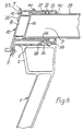
- the Profile hinge 5 includes in addition to the free leg mentioned 4, opposite one near the unmarked Section located hinge axis is angled second free leg 6, which is angled so that it in the closed position of the profile hinge - see Fig. 1 and 6 - runs parallel to the first-mentioned free leg 4.
- the second free leg 6 of the profile hinge 5 is on attached a fan frame profile, generally designated 7, which is made of extruded aluminum.
- the fan frame profile 7 can be seen from an outer first section 8 box-shaped cross-section and one inside lying second section 9 approximately C-shaped cross section think together, the first section 8 and the second section 9 have an inner wall 10 in common.
- the outer first section 8 is essentially shaped as a crooked parallelepiped, the bottom of one Outer wall 11 is inclined upward to the inner wall 10, wherein the outer wall 11 and the inner wall 10 parallel to each other run.
- outer first section 8 box-shaped cross section from below inclined upwards and outwards. This slope of the outer edge area 12 serves in conjunction, as will be discussed below with further shaped elements of the first profile part, which is generally designated 13 for connection to a second profile part, generally designated 14, which is injection molded from PVC, see Fig. 6.
- One top and one bottom of the parallelepiped of the outer first portion 8 forming sides are as Grooves 18, 19 formed, in such a way that in these grooves 18, 19 flat corner connection brackets 20, 21 inserted above and below and riveted to the outer first section 8 can, see Fig. 4.
- Fig. 4 are rivets with the reference numerals 22 and 23 provided.
- the serve Corner connection bracket 20, 21 for connecting two miters cut first profile parts 13, 13 'as a corner connection.
- a downward web 28 which are supported directly on the contact surface 3 can, if the fan flap is closed and so contact forces can keep away from the profile hinge 5.
- An upper leg 29 of the inner second section 9 has along its upper inner edge 30 an upward protruding Thickening 31, which is another shape element for Clip on or snap on the second profile part 14, see Fig. 6, in which this forms a downward web 32 comprises, which comes to rest on the thickening 31.
- the second profile part 14 is in cross section as formed approximately right angle, with one on the inside of the second profile part 14 lying leg 33 box-shaped is reinforced, see Fig. 7, in this profile part 14 is shown separately.
- the second profile part 14 is on the first profile part 13 plugged in, so that the first profile part 13 on its top and inside essentially is enclosed. There is an upper side 34 of the second profile part 14 above the first section 8 and the second section 9 of the first profile part 13.
- the top is for attachment to the first profile part 13 of the second profile part 14, as can be seen from FIGS. 6 and 7, angled downwards, so that an angled section 35 over the outer wall region 12 of the first profile part 13 at the Assembly slip and then a snap connection or clamp connection can form.
- the second profile part 14 on its lower outer edge 36, which lies further inside as an upper outer edge 37, angled upwards. From the lower outer edge 36 is still as in FIGS. 6 and 7 shown, a sealing strip 38 projecting downward is formed, sealing on the top 3 of the curb 2 is present when the fan flap is closed.
- An upper cross member 39 belonging to the fan frame can directly in the open cross-section adapted to its dimensions of the inner second section 9 C-shaped Cross section inserted and assembled.
- the upper crossbar 39 is tall as a square tube or profile. So there is a direct non-positive connection between the upper cross member 39 and the first profile part 13th
- the modified first Extruded aluminum section designated 41 In the preferred modified embodiment of the fan frame profile 9-12 is the modified first Extruded aluminum section designated 41, this in turn as in the first embodiment on one Stacking frame 1 rests.
- the modified first profile part 41 forms together with a clamping profile 48 and a second modified profile part 60 a frame of a dome, in particular light dome 50, of which two sections indicated discs are designated 68, 69.
- the disks 68 and 69 are interposed by two sealing elements 70, 71, as shown in Fig. 9, between the clamping profile 48 and an upper side 47 of the modified first profile part 41, see also Fig.
- the modified first profile part shows the following special features:
- a first box-shaped section 42 of the first profile part 41 is not, as in the embodiment according to FIGS. 1 and 2, cuboid in cross-section, but trapezoidal in shape by an inclined outer wall 52 corresponding to the inclined outer wall 11 of the first embodiment, but which is vertical Wall 43 faces inside.
- the vertical wall 43 is particularly well suited to absorb pressure forces which by screws 58 onto the first box-shaped section 42 of the modified first profile part 41 are exercised, wherein the screws through first through holes 45 in the horizontal Wall section 44 and second through holes 46 on the Pass through the top 47 and into a screw profile 59 in the clamping profile 48 are screwed.
- the modified first profile part 41 in the upper A horizontally circumferential nose 53 in the area of its outer wall 52 on.
- a recess 54 in the nose 53 takes a sealing projection 55, which consists of a hood-shaped section 49 of the clamping profile 48 protrudes. It becomes a labyrinthine sealing transition between the modified first Profile part 41 and the clamping profile 48 created, which also an exact space between the top 47 of the modified first profile part and an unmarked Underside of a reinforced edge 56 of the clamping profile 48 defines the disks 68, 69 including sealing elements 70, 71 records.
- the reinforced edge 56 of the clamping profile 48, the inside runs wedge-shaped, has an undercut 57 to the outside on.
- a shoe-shaped edge of the upper disk 68 can be fixed.
- the modified second profile part 60 does not point like that second profile part of the first embodiment a horizontal Section on top of a box-shaped vertical Significant protrudes leg, compare first embodiment 7, in which the leg designated 33 with the modified embodiment according to FIG. 12. Instead, the modified second profile part 60 is on its upper outer edge 64 a groove 65, in which the after reinforcement 66 protruding below in the second section of the modified first profile part 41, see FIG. 9 and 12.
- the modified second profile part 60 In its lower area is the modified second profile part 60 similar to the second profile part of the first embodiment on its lower outer edge 61 with a lower, formed as a locking tab strip outer edge 61.
- the Latching stripe is thus suitable in an unmarked Engage groove that of the groove 26 in the embodiment 2 corresponds to.
- the one shaped as a tab lower outer edge 61 of the modified second profile part 60 is particularly flexible because the lower horizontal wall, which is in Fig. 12 is not designated, except for one designated inner wall of the box-shaped profile zoom ranges.
- Standing down from this flexible bottom From the outer edge from a resilient sealing strip 67 ', which is suitable the widened curb of the curb 1 to lie on, see Fig. 9.
- the fan frame profile is at rest together with the clamped disks 68, 69 of the hood 50 via a web 72, the bottom of the modified first Profile part 41 protrudes on the widened curb of the Stacking frame 1.
Landscapes
- Engineering & Computer Science (AREA)
- Combustion & Propulsion (AREA)
- Mechanical Engineering (AREA)
- General Engineering & Computer Science (AREA)
- Chemical & Material Sciences (AREA)
- Specific Sealing Or Ventilating Devices For Doors And Windows (AREA)
- Building Environments (AREA)
- Body Structure For Vehicles (AREA)
- Air-Flow Control Members (AREA)
- Walking Sticks, Umbrellas, And Fans (AREA)
- Projection Apparatus (AREA)
- Waste-Gas Treatment And Other Accessory Devices For Furnaces (AREA)
- Air-Conditioning For Vehicles (AREA)
- Sorption Type Refrigeration Machines (AREA)
Applications Claiming Priority (2)
| Application Number | Priority Date | Filing Date | Title |
|---|---|---|---|
| DE19617574A DE19617574C1 (de) | 1996-05-02 | 1996-05-02 | Lüfterrahmenprofil, insbesondere für eine Rauch- und Wärmeabzugsanlage |
| DE19617574 | 1996-05-02 |
Publications (3)
| Publication Number | Publication Date |
|---|---|
| EP0805315A2 EP0805315A2 (de) | 1997-11-05 |
| EP0805315A3 EP0805315A3 (de) | 2001-04-25 |
| EP0805315B1 true EP0805315B1 (de) | 2004-07-28 |
Family
ID=7793093
Family Applications (1)
| Application Number | Title | Priority Date | Filing Date |
|---|---|---|---|
| EP97106072A Expired - Lifetime EP0805315B1 (de) | 1996-05-02 | 1997-04-14 | Lüfterrahmenprofil, insbesondere für eine Rauch- und Wärmeabzugsanlage |
Country Status (8)
| Country | Link |
|---|---|
| EP (1) | EP0805315B1 (pl) |
| AT (1) | ATE272195T1 (pl) |
| CZ (1) | CZ292501B6 (pl) |
| DE (2) | DE19617574C1 (pl) |
| DK (1) | DK0805315T3 (pl) |
| ES (1) | ES2221001T3 (pl) |
| HU (1) | HU219554B (pl) |
| PL (1) | PL184179B1 (pl) |
Families Citing this family (1)
| Publication number | Priority date | Publication date | Assignee | Title |
|---|---|---|---|---|
| CN109028532B (zh) * | 2018-08-07 | 2023-12-15 | 宁波鑫隆净化设备有限公司 | 高效外装配隔冷热空调风机箱体 |
Family Cites Families (4)
| Publication number | Priority date | Publication date | Assignee | Title |
|---|---|---|---|---|
| US4439962A (en) * | 1978-07-10 | 1984-04-03 | Wasco Products, Inc. | Skylight construction |
| DE3338092C3 (de) * | 1983-10-20 | 1994-08-04 | Eberspaecher J | Vorrichtung zum rauch- und waermeabzug sowie zum be- und entlueften von geschlossenen raeumen |
| US4928445A (en) * | 1988-12-13 | 1990-05-29 | Wasco Products, Inc. | Skylight construction |
| DE4016528C2 (de) * | 1990-05-22 | 1999-07-15 | Eternit Ag | Belichtungs- und Belüftungselement mit einem Hohlprofil-Aufstellrahmen |
-
1996
- 1996-05-02 DE DE19617574A patent/DE19617574C1/de not_active Expired - Lifetime
-
1997
- 1997-04-14 DE DE59711799T patent/DE59711799D1/de not_active Expired - Lifetime
- 1997-04-14 AT AT97106072T patent/ATE272195T1/de active
- 1997-04-14 EP EP97106072A patent/EP0805315B1/de not_active Expired - Lifetime
- 1997-04-14 DK DK97106072T patent/DK0805315T3/da active
- 1997-04-14 ES ES97106072T patent/ES2221001T3/es not_active Expired - Lifetime
- 1997-04-29 PL PL97319740A patent/PL184179B1/pl unknown
- 1997-04-30 HU HU9700835A patent/HU219554B/hu not_active IP Right Cessation
- 1997-04-30 CZ CZ19971334A patent/CZ292501B6/cs not_active IP Right Cessation
Also Published As
| Publication number | Publication date |
|---|---|
| CZ133497A3 (en) | 1997-11-12 |
| EP0805315A3 (de) | 2001-04-25 |
| DE59711799D1 (de) | 2004-09-02 |
| EP0805315A2 (de) | 1997-11-05 |
| ATE272195T1 (de) | 2004-08-15 |
| PL184179B1 (pl) | 2002-09-30 |
| DE19617574C1 (de) | 1997-11-27 |
| PL319740A1 (en) | 1997-11-10 |
| CZ292501B6 (cs) | 2003-10-15 |
| DK0805315T3 (da) | 2004-09-06 |
| HU219554B (hu) | 2001-05-28 |
| ES2221001T3 (es) | 2004-12-16 |
| HUP9700835A1 (en) | 1997-11-28 |
| HU9700835D0 (en) | 1997-06-30 |
Similar Documents
| Publication | Publication Date | Title |
|---|---|---|
| EP0085173A1 (de) | Lüftungseinrichtung | |
| DE2923734A1 (de) | Lueftungsvorrichtung zum einbau in fenster- oder tuerrahmen | |
| DE3243657C2 (de) | Lüfter | |
| CH658900A5 (de) | Lueftungsvorrichtung fuer den einbau in wandoeffnungen von gebaeuden, insbesondere in fenster- und tueroeffnungen. | |
| EP0805315B1 (de) | Lüfterrahmenprofil, insbesondere für eine Rauch- und Wärmeabzugsanlage | |
| EP0512227B1 (de) | Jalousie zur Abdeckung von Lüftungsöffnungen in Gebäuden | |
| EP0428775B1 (de) | Vorrichtung zur Hinterlüftung von Dächern | |
| EP0750089B1 (de) | Fenster mit Blendrahmen | |
| DE2543979A1 (de) | Be- und entlueftungsvorrichtung fuer gebaeuderaeume | |
| DE19855028B4 (de) | Dachfensterkonstruktionen | |
| DE3118559A1 (de) | Fensterseitenwand fuer personenbefoerderungsfahrzeuge | |
| DE4023494C2 (de) | Lüftungsvorrichtung | |
| EP0922828A2 (de) | Fenster mit Vorsatzscheibe | |
| EP0463637B1 (de) | Firstentlüftungssystem | |
| DE3909296C2 (de) | Belüftungsvorrichtung für Gebäudedächer | |
| DE3035230C2 (de) | Dachwindabweiser für Kraftfahrzeugschiebedächer | |
| DE202006014016U1 (de) | Dachelement | |
| DE2829241A1 (de) | Belueftungsvorrichtung fuer ein fahrzeugfenster | |
| EP0331810B1 (de) | Profilrahmen | |
| EP0744121A1 (de) | Gewächshaus | |
| CH675443A5 (pl) | ||
| EP0230998A2 (de) | Torblatt mit Belüftungsöffnungen | |
| DE29912300U1 (de) | Befestigungsvorrichtung | |
| EP0833017A2 (de) | Befestigungsvorrichtung | |
| DE3133379C2 (pl) |
Legal Events
| Date | Code | Title | Description |
|---|---|---|---|
| PUAI | Public reference made under article 153(3) epc to a published international application that has entered the european phase |
Free format text: ORIGINAL CODE: 0009012 |
|
| AK | Designated contracting states |
Kind code of ref document: A2 Designated state(s): AT BE CH DE DK ES FI FR GB GR IE IT LI LU MC NL PT SE |
|
| PUAL | Search report despatched |
Free format text: ORIGINAL CODE: 0009013 |
|
| AK | Designated contracting states |
Kind code of ref document: A3 Designated state(s): AT BE CH DE DK ES FI FR GB GR IE IT LI LU MC NL PT SE |
|
| RIC1 | Information provided on ipc code assigned before grant |
Free format text: 7F 24F 13/18 A, 7F 24F 7/02 B, 7F 24F 13/14 B, 7E 04D 13/03 B |
|
| 17P | Request for examination filed |
Effective date: 20010607 |
|
| GRAP | Despatch of communication of intention to grant a patent |
Free format text: ORIGINAL CODE: EPIDOSNIGR1 |
|
| GRAS | Grant fee paid |
Free format text: ORIGINAL CODE: EPIDOSNIGR3 |
|
| GRAA | (expected) grant |
Free format text: ORIGINAL CODE: 0009210 |
|
| AK | Designated contracting states |
Kind code of ref document: B1 Designated state(s): AT BE CH DE DK ES FI FR GB GR IE IT LI LU MC NL PT SE |
|
| PG25 | Lapsed in a contracting state [announced via postgrant information from national office to epo] |
Ref country code: IE Free format text: LAPSE BECAUSE OF FAILURE TO SUBMIT A TRANSLATION OF THE DESCRIPTION OR TO PAY THE FEE WITHIN THE PRESCRIBED TIME-LIMIT Effective date: 20040728 Ref country code: FI Free format text: LAPSE BECAUSE OF FAILURE TO SUBMIT A TRANSLATION OF THE DESCRIPTION OR TO PAY THE FEE WITHIN THE PRESCRIBED TIME-LIMIT Effective date: 20040728 |
|
| REG | Reference to a national code |
Ref country code: GB Ref legal event code: FG4D Free format text: NOT ENGLISH |
|
| REG | Reference to a national code |
Ref country code: CH Ref legal event code: EP |
|
| REG | Reference to a national code |
Ref country code: CH Ref legal event code: NV Representative=s name: A. BRAUN, BRAUN, HERITIER, ESCHMANN AG PATENTANWAE |
|
| GBT | Gb: translation of ep patent filed (gb section 77(6)(a)/1977) |
Effective date: 20040728 |
|
| REG | Reference to a national code |
Ref country code: IE Ref legal event code: FG4D Free format text: GERMAN |
|
| REF | Corresponds to: |
Ref document number: 59711799 Country of ref document: DE Date of ref document: 20040902 Kind code of ref document: P |
|
| REG | Reference to a national code |
Ref country code: DK Ref legal event code: T3 |
|
| PG25 | Lapsed in a contracting state [announced via postgrant information from national office to epo] |
Ref country code: SE Free format text: LAPSE BECAUSE OF FAILURE TO SUBMIT A TRANSLATION OF THE DESCRIPTION OR TO PAY THE FEE WITHIN THE PRESCRIBED TIME-LIMIT Effective date: 20041028 Ref country code: GR Free format text: LAPSE BECAUSE OF FAILURE TO SUBMIT A TRANSLATION OF THE DESCRIPTION OR TO PAY THE FEE WITHIN THE PRESCRIBED TIME-LIMIT Effective date: 20041028 |
|
| REG | Reference to a national code |
Ref country code: ES Ref legal event code: FG2A Ref document number: 2221001 Country of ref document: ES Kind code of ref document: T3 |
|
| ET | Fr: translation filed | ||
| REG | Reference to a national code |
Ref country code: IE Ref legal event code: FD4D |
|
| PG25 | Lapsed in a contracting state [announced via postgrant information from national office to epo] |
Ref country code: LU Free format text: LAPSE BECAUSE OF NON-PAYMENT OF DUE FEES Effective date: 20050414 |
|
| PG25 | Lapsed in a contracting state [announced via postgrant information from national office to epo] |
Ref country code: MC Free format text: LAPSE BECAUSE OF NON-PAYMENT OF DUE FEES Effective date: 20050430 |
|
| PLBE | No opposition filed within time limit |
Free format text: ORIGINAL CODE: 0009261 |
|
| STAA | Information on the status of an ep patent application or granted ep patent |
Free format text: STATUS: NO OPPOSITION FILED WITHIN TIME LIMIT |
|
| 26N | No opposition filed |
Effective date: 20050429 |
|
| PG25 | Lapsed in a contracting state [announced via postgrant information from national office to epo] |
Ref country code: PT Free format text: LAPSE BECAUSE OF NON-PAYMENT OF DUE FEES Effective date: 20041228 |
|
| REG | Reference to a national code |
Ref country code: CH Ref legal event code: PFA Owner name: GRASL, ANDREAS Free format text: GRASL, ANDREAS#WIENER STRASSE 23#3452 HEILIGENEICH (AT) -TRANSFER TO- GRASL, ANDREAS#WIENER STRASSE 23#3452 HEILIGENEICH (AT) |
|
| PGFP | Annual fee paid to national office [announced via postgrant information from national office to epo] |
Ref country code: ES Payment date: 20080423 Year of fee payment: 12 |
|
| REG | Reference to a national code |
Ref country code: ES Ref legal event code: FD2A Effective date: 20090415 |
|
| PG25 | Lapsed in a contracting state [announced via postgrant information from national office to epo] |
Ref country code: ES Free format text: LAPSE BECAUSE OF NON-PAYMENT OF DUE FEES Effective date: 20090415 |
|
| PGFP | Annual fee paid to national office [announced via postgrant information from national office to epo] |
Ref country code: NL Payment date: 20110502 Year of fee payment: 15 Ref country code: DK Payment date: 20110426 Year of fee payment: 15 Ref country code: GB Payment date: 20110421 Year of fee payment: 15 Ref country code: BE Payment date: 20110426 Year of fee payment: 15 |
|
| BERE | Be: lapsed |
Owner name: *GRASL ANDREAS Effective date: 20120430 |
|
| REG | Reference to a national code |
Ref country code: NL Ref legal event code: V1 Effective date: 20121101 |
|
| REG | Reference to a national code |
Ref country code: DK Ref legal event code: EBP |
|
| GBPC | Gb: european patent ceased through non-payment of renewal fee |
Effective date: 20120414 |
|
| PG25 | Lapsed in a contracting state [announced via postgrant information from national office to epo] |
Ref country code: GB Free format text: LAPSE BECAUSE OF NON-PAYMENT OF DUE FEES Effective date: 20120414 Ref country code: BE Free format text: LAPSE BECAUSE OF NON-PAYMENT OF DUE FEES Effective date: 20120430 |
|
| PG25 | Lapsed in a contracting state [announced via postgrant information from national office to epo] |
Ref country code: NL Free format text: LAPSE BECAUSE OF NON-PAYMENT OF DUE FEES Effective date: 20121101 |
|
| PGFP | Annual fee paid to national office [announced via postgrant information from national office to epo] |
Ref country code: CH Payment date: 20130429 Year of fee payment: 17 |
|
| PGFP | Annual fee paid to national office [announced via postgrant information from national office to epo] |
Ref country code: IT Payment date: 20130419 Year of fee payment: 17 Ref country code: FR Payment date: 20130523 Year of fee payment: 17 |
|
| PG25 | Lapsed in a contracting state [announced via postgrant information from national office to epo] |
Ref country code: DK Free format text: LAPSE BECAUSE OF NON-PAYMENT OF DUE FEES Effective date: 20120430 |
|
| REG | Reference to a national code |
Ref country code: CH Ref legal event code: PCAR Free format text: NEW ADDRESS: HOLBEINSTRASSE 36-38, 4051 BASEL (CH) |
|
| REG | Reference to a national code |
Ref country code: CH Ref legal event code: PL |
|
| REG | Reference to a national code |
Ref country code: FR Ref legal event code: ST Effective date: 20141231 |
|
| PG25 | Lapsed in a contracting state [announced via postgrant information from national office to epo] |
Ref country code: CH Free format text: LAPSE BECAUSE OF NON-PAYMENT OF DUE FEES Effective date: 20140430 Ref country code: LI Free format text: LAPSE BECAUSE OF NON-PAYMENT OF DUE FEES Effective date: 20140430 |
|
| PG25 | Lapsed in a contracting state [announced via postgrant information from national office to epo] |
Ref country code: FR Free format text: LAPSE BECAUSE OF NON-PAYMENT OF DUE FEES Effective date: 20140430 |
|
| PG25 | Lapsed in a contracting state [announced via postgrant information from national office to epo] |
Ref country code: IT Free format text: LAPSE BECAUSE OF NON-PAYMENT OF DUE FEES Effective date: 20140414 |
|
| PGFP | Annual fee paid to national office [announced via postgrant information from national office to epo] |
Ref country code: DE Payment date: 20160420 Year of fee payment: 20 |
|
| PGFP | Annual fee paid to national office [announced via postgrant information from national office to epo] |
Ref country code: AT Payment date: 20160426 Year of fee payment: 20 |
|
| REG | Reference to a national code |
Ref country code: DE Ref legal event code: R071 Ref document number: 59711799 Country of ref document: DE |
|
| REG | Reference to a national code |
Ref country code: AT Ref legal event code: MK07 Ref document number: 272195 Country of ref document: AT Kind code of ref document: T Effective date: 20170414 |