EP0805032A2 - Behälter für Flüssigkeit, Tintenstrahlkassette mit diesem Behälter für Flüssigkeit und Tintenstrahlapparat mit dieser Tintenstrahlkassette - Google Patents
Behälter für Flüssigkeit, Tintenstrahlkassette mit diesem Behälter für Flüssigkeit und Tintenstrahlapparat mit dieser Tintenstrahlkassette Download PDFInfo
- Publication number
- EP0805032A2 EP0805032A2 EP97109850A EP97109850A EP0805032A2 EP 0805032 A2 EP0805032 A2 EP 0805032A2 EP 97109850 A EP97109850 A EP 97109850A EP 97109850 A EP97109850 A EP 97109850A EP 0805032 A2 EP0805032 A2 EP 0805032A2
- Authority
- EP
- European Patent Office
- Prior art keywords
- ink
- ink jet
- negative pressure
- chamber
- pressure generating
- Prior art date
- Legal status (The legal status is an assumption and is not a legal conclusion. Google has not performed a legal analysis and makes no representation as to the accuracy of the status listed.)
- Granted
Links
- 239000007788 liquid Substances 0.000 title claims abstract description 68
- 239000012298 atmosphere Substances 0.000 claims abstract description 98
- 238000005192 partition Methods 0.000 claims abstract description 37
- 238000007599 discharging Methods 0.000 claims description 16
- 230000008859 change Effects 0.000 claims description 2
- 239000000976 ink Substances 0.000 description 731
- 239000010410 layer Substances 0.000 description 18
- 230000001965 increasing effect Effects 0.000 description 16
- 238000000034 method Methods 0.000 description 16
- 230000033001 locomotion Effects 0.000 description 15
- 238000009826 distribution Methods 0.000 description 13
- 238000010276 construction Methods 0.000 description 12
- 239000006260 foam Substances 0.000 description 9
- 230000001737 promoting effect Effects 0.000 description 9
- 230000000694 effects Effects 0.000 description 8
- 230000006870 function Effects 0.000 description 8
- 230000005499 meniscus Effects 0.000 description 7
- 238000001704 evaporation Methods 0.000 description 6
- 230000008020 evaporation Effects 0.000 description 6
- 239000000835 fiber Substances 0.000 description 6
- 238000004519 manufacturing process Methods 0.000 description 6
- 230000008569 process Effects 0.000 description 6
- 238000011084 recovery Methods 0.000 description 6
- XLYOFNOQVPJJNP-UHFFFAOYSA-N water Substances O XLYOFNOQVPJJNP-UHFFFAOYSA-N 0.000 description 6
- 239000000853 adhesive Substances 0.000 description 5
- 230000001070 adhesive effect Effects 0.000 description 5
- 230000007423 decrease Effects 0.000 description 5
- 230000007613 environmental effect Effects 0.000 description 5
- 238000004299 exfoliation Methods 0.000 description 5
- 238000000465 moulding Methods 0.000 description 5
- 238000007639 printing Methods 0.000 description 5
- 239000000758 substrate Substances 0.000 description 5
- 230000015572 biosynthetic process Effects 0.000 description 4
- 238000004891 communication Methods 0.000 description 4
- 238000003780 insertion Methods 0.000 description 4
- 230000037431 insertion Effects 0.000 description 4
- 238000004806 packaging method and process Methods 0.000 description 4
- -1 polypropylene Polymers 0.000 description 4
- 230000002829 reductive effect Effects 0.000 description 4
- 238000000638 solvent extraction Methods 0.000 description 4
- XAGFODPZIPBFFR-UHFFFAOYSA-N aluminium Chemical compound [Al] XAGFODPZIPBFFR-UHFFFAOYSA-N 0.000 description 3
- 229910052782 aluminium Inorganic materials 0.000 description 3
- 238000009835 boiling Methods 0.000 description 3
- 210000000078 claw Anatomy 0.000 description 3
- 230000001681 protective effect Effects 0.000 description 3
- 238000003466 welding Methods 0.000 description 3
- 239000004677 Nylon Substances 0.000 description 2
- 239000004743 Polypropylene Substances 0.000 description 2
- XUIMIQQOPSSXEZ-UHFFFAOYSA-N Silicon Chemical compound [Si] XUIMIQQOPSSXEZ-UHFFFAOYSA-N 0.000 description 2
- 239000012790 adhesive layer Substances 0.000 description 2
- 230000004888 barrier function Effects 0.000 description 2
- 230000006835 compression Effects 0.000 description 2
- 238000007906 compression Methods 0.000 description 2
- 230000001276 controlling effect Effects 0.000 description 2
- 238000011049 filling Methods 0.000 description 2
- 238000001746 injection moulding Methods 0.000 description 2
- 229920001778 nylon Polymers 0.000 description 2
- 239000012466 permeate Substances 0.000 description 2
- 239000004033 plastic Substances 0.000 description 2
- 229920003023 plastic Polymers 0.000 description 2
- 239000002985 plastic film Substances 0.000 description 2
- 229920006255 plastic film Polymers 0.000 description 2
- 229920001155 polypropylene Polymers 0.000 description 2
- 238000003825 pressing Methods 0.000 description 2
- 230000001105 regulatory effect Effects 0.000 description 2
- 239000011347 resin Substances 0.000 description 2
- 229920005989 resin Polymers 0.000 description 2
- 230000004044 response Effects 0.000 description 2
- 229910052710 silicon Inorganic materials 0.000 description 2
- 239000010703 silicon Substances 0.000 description 2
- 238000003860 storage Methods 0.000 description 2
- 239000004698 Polyethylene Substances 0.000 description 1
- 229920005830 Polyurethane Foam Polymers 0.000 description 1
- 230000009471 action Effects 0.000 description 1
- 230000008901 benefit Effects 0.000 description 1
- 230000005587 bubbling Effects 0.000 description 1
- 239000003795 chemical substances by application Substances 0.000 description 1
- 239000003086 colorant Substances 0.000 description 1
- 239000012141 concentrate Substances 0.000 description 1
- 230000003247 decreasing effect Effects 0.000 description 1
- 230000000994 depressogenic effect Effects 0.000 description 1
- 238000001035 drying Methods 0.000 description 1
- 230000002708 enhancing effect Effects 0.000 description 1
- 238000005530 etching Methods 0.000 description 1
- 230000009969 flowable effect Effects 0.000 description 1
- 239000011888 foil Substances 0.000 description 1
- 238000010438 heat treatment Methods 0.000 description 1
- 230000001771 impaired effect Effects 0.000 description 1
- 230000000977 initiatory effect Effects 0.000 description 1
- 238000002347 injection Methods 0.000 description 1
- 239000007924 injection Substances 0.000 description 1
- 230000010354 integration Effects 0.000 description 1
- 230000009545 invasion Effects 0.000 description 1
- 238000005304 joining Methods 0.000 description 1
- 230000007774 longterm Effects 0.000 description 1
- 238000012423 maintenance Methods 0.000 description 1
- 230000007246 mechanism Effects 0.000 description 1
- 238000002156 mixing Methods 0.000 description 1
- 230000004048 modification Effects 0.000 description 1
- 238000012986 modification Methods 0.000 description 1
- 230000035515 penetration Effects 0.000 description 1
- 229920000573 polyethylene Polymers 0.000 description 1
- 229920000139 polyethylene terephthalate Polymers 0.000 description 1
- 239000005020 polyethylene terephthalate Substances 0.000 description 1
- 239000011496 polyurethane foam Substances 0.000 description 1
- 239000011148 porous material Substances 0.000 description 1
- 230000002265 prevention Effects 0.000 description 1
- 239000000047 product Substances 0.000 description 1
- 230000009467 reduction Effects 0.000 description 1
- 230000000717 retained effect Effects 0.000 description 1
- 230000002441 reversible effect Effects 0.000 description 1
- 238000007789 sealing Methods 0.000 description 1
- 239000004065 semiconductor Substances 0.000 description 1
- 238000007493 shaping process Methods 0.000 description 1
- 238000004544 sputter deposition Methods 0.000 description 1
- 230000006641 stabilisation Effects 0.000 description 1
- 238000011105 stabilization Methods 0.000 description 1
- 230000000087 stabilizing effect Effects 0.000 description 1
- 230000003068 static effect Effects 0.000 description 1
- 238000011282 treatment Methods 0.000 description 1
- 238000007740 vapor deposition Methods 0.000 description 1
- 238000009834 vaporization Methods 0.000 description 1
- 230000008016 vaporization Effects 0.000 description 1
- 238000009736 wetting Methods 0.000 description 1
Images


Classifications
-
- B—PERFORMING OPERATIONS; TRANSPORTING
- B41—PRINTING; LINING MACHINES; TYPEWRITERS; STAMPS
- B41J—TYPEWRITERS; SELECTIVE PRINTING MECHANISMS, i.e. MECHANISMS PRINTING OTHERWISE THAN FROM A FORME; CORRECTION OF TYPOGRAPHICAL ERRORS
- B41J2/00—Typewriters or selective printing mechanisms characterised by the printing or marking process for which they are designed
- B41J2/005—Typewriters or selective printing mechanisms characterised by the printing or marking process for which they are designed characterised by bringing liquid or particles selectively into contact with a printing material
- B41J2/01—Ink jet
- B41J2/17—Ink jet characterised by ink handling
- B41J2/175—Ink supply systems ; Circuit parts therefor
- B41J2/17503—Ink cartridges
- B41J2/17556—Means for regulating the pressure in the cartridge
-
- B—PERFORMING OPERATIONS; TRANSPORTING
- B41—PRINTING; LINING MACHINES; TYPEWRITERS; STAMPS
- B41J—TYPEWRITERS; SELECTIVE PRINTING MECHANISMS, i.e. MECHANISMS PRINTING OTHERWISE THAN FROM A FORME; CORRECTION OF TYPOGRAPHICAL ERRORS
- B41J2/00—Typewriters or selective printing mechanisms characterised by the printing or marking process for which they are designed
- B41J2/005—Typewriters or selective printing mechanisms characterised by the printing or marking process for which they are designed characterised by bringing liquid or particles selectively into contact with a printing material
- B41J2/01—Ink jet
- B41J2/17—Ink jet characterised by ink handling
- B41J2/175—Ink supply systems ; Circuit parts therefor
- B41J2/17503—Ink cartridges
- B41J2/17513—Inner structure
-
- B—PERFORMING OPERATIONS; TRANSPORTING
- B41—PRINTING; LINING MACHINES; TYPEWRITERS; STAMPS
- B41J—TYPEWRITERS; SELECTIVE PRINTING MECHANISMS, i.e. MECHANISMS PRINTING OTHERWISE THAN FROM A FORME; CORRECTION OF TYPOGRAPHICAL ERRORS
- B41J2/00—Typewriters or selective printing mechanisms characterised by the printing or marking process for which they are designed
- B41J2/005—Typewriters or selective printing mechanisms characterised by the printing or marking process for which they are designed characterised by bringing liquid or particles selectively into contact with a printing material
- B41J2/01—Ink jet
- B41J2/17—Ink jet characterised by ink handling
- B41J2/175—Ink supply systems ; Circuit parts therefor
- B41J2/17503—Ink cartridges
- B41J2/17533—Storage or packaging of ink cartridges
-
- B—PERFORMING OPERATIONS; TRANSPORTING
- B41—PRINTING; LINING MACHINES; TYPEWRITERS; STAMPS
- B41J—TYPEWRITERS; SELECTIVE PRINTING MECHANISMS, i.e. MECHANISMS PRINTING OTHERWISE THAN FROM A FORME; CORRECTION OF TYPOGRAPHICAL ERRORS
- B41J2/00—Typewriters or selective printing mechanisms characterised by the printing or marking process for which they are designed
- B41J2/005—Typewriters or selective printing mechanisms characterised by the printing or marking process for which they are designed characterised by bringing liquid or particles selectively into contact with a printing material
- B41J2/01—Ink jet
- B41J2/17—Ink jet characterised by ink handling
- B41J2/175—Ink supply systems ; Circuit parts therefor
- B41J2/17503—Ink cartridges
- B41J2/17536—Protection of cartridges or parts thereof, e.g. tape
-
- B—PERFORMING OPERATIONS; TRANSPORTING
- B41—PRINTING; LINING MACHINES; TYPEWRITERS; STAMPS
- B41J—TYPEWRITERS; SELECTIVE PRINTING MECHANISMS, i.e. MECHANISMS PRINTING OTHERWISE THAN FROM A FORME; CORRECTION OF TYPOGRAPHICAL ERRORS
- B41J2/00—Typewriters or selective printing mechanisms characterised by the printing or marking process for which they are designed
- B41J2/005—Typewriters or selective printing mechanisms characterised by the printing or marking process for which they are designed characterised by bringing liquid or particles selectively into contact with a printing material
- B41J2/01—Ink jet
- B41J2/17—Ink jet characterised by ink handling
- B41J2/175—Ink supply systems ; Circuit parts therefor
- B41J2/17503—Ink cartridges
- B41J2/17553—Outer structure
Definitions
- a recording apparatus of the ink jet system performs the recording by discharging the ink from recording means (recording head) onto the recording medium, having the following advantages.
- the recording means can be made compact, high definition image can be recorded at high speed, the ordinary paper can be used for the recording without any special treatments, the running cost is low, the noise is small owing to the non-impact method, and the color image is easily recorded by using color inks.
- a line-type recording apparatus using recording means of the line-type in which a number of discharge ports are arranged in a direction of sheet width allows the higher speed recording.
- Figs. 23A to 23D are cross-sectional views for sequentially explaining the ink pouring process into the ink tank unit of the ink jet cartridge as shown in Figs. 13 to 16.
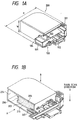
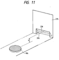
- Figs. 1A and 1B show one embodiment of an ink jet cartridge which is mountable on a carriage of an ink jet recording apparatus.
- Fig. 1A is an external perspective view of the ink jet cartridge of the present invention
- Fig. 1B is a perspective projection view of an ink tank unit, with the recording head unit removed from the ink jet cartridge as shown in Fig. 1A, as seen through one lateral side (which corresponds to the bottom face of the ink tank unit which is an ink reservoir in this embodiment).
- the ink jet cartridge in this embodiment has an ordinary ink tank unit 200 and a head unit 100 connected, as shown in Fig. 1A, and is detachably mounted on a carriage (not shown) of the ink jet recording apparatus, with a dischorge port portion 101 faced downward.
- the head unit 100 as shown in Fig. 1B can be detached from the ink tank unit 200.
- 104 is a head side absorbing member provided for the recovery of recovery member for the ink discharge port portion 101 provided on the ink jet head unit 100, the details of which will be described later.
- the ink storing portion has one and half or more the volume of the negative pressure generating member receiving portion, wherein the greater ink capacity is achieved by increasing the ratio of the ink storage to the volume of the ink storing portion of the ink vessel, as compared with the conventional constitution of the ink storing portion for storing the ink using only an ink absorbing member.
- the ink supply from the ink storing portion 204 to the netative pressure generating member receiving portion 203 is carried out in response to pressure changes upon the ink consumption of the head unit (not shown).
- the possibility of the ink flow passage formed in the ink concentrated portion can be further reduced, resulting in stabler ink distribution to collect the ink only near the ink supply port 209 more securely.
- curvature is provided at the four corners, it is noted that multi-angle may be made to eliminate the angle at the four corners to prevent exfoliation.
- profile of R is most preferable from the aspect of the insertion precision or even insertion.
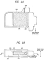
- Figs. 4A and 4B show internal structures of another ink tank unit for use in the ink jet cartridge of the present invention which is mounted on the ink jet recording apparatus according to an embodiment 3.
- like symbols are attached to the parts having the same functions as in the previous embodiment 1.
- an ink storing portion is extended on both sides of negative pressure generating member receiving portion along a direction crosswise to the main scan direction when mounting the ink cartridge by a partition portion 215 in this cartridge, with the ink storing portion like a U-character.
- the direction of supplying the ink via the ink communicating portion 206 from the ink storing portion to the negative pressure generating member receiving chamber is made a longitudinal direction of the ink storing portion, so that the ink storing amount is increased.
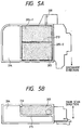
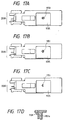
- Figs. 5A and 5B show the internal structures of another ink tank unit for use in the ink jet cartridge of the present invention as an embodiment 4.
- like symbols are attached to the parts having the same functions as in the previous embodiment.
- an absorbing member 205 within the negative pressure generating member receiving portion 203 is divided into two portions 205-1 and 205-2, and a gap 213 serving as a meniscus generating portion is provided so that a meniscus may be formed between these portions 205-1 and 205-2.
- Fig. 6 shows an instance where the ink is filled in the ink jet cartridge of this embodiment.
- the ink is held by the meniscus generating portion 213, and the ink is difficult to flow to the portion 205-1, so that the ink leakage from the atmosphere communicating port 208 is less likely to occur.
- This buffer chamber is secured within the negative pressure generating member receiving portion by a rib 214 to store the ink overflowing from the ink absorbing member due to environmental changes as previously described, preventing the ink from reaching the atmosphere communicating port portion.
- the reliability in preventing the ink leakage is enhanced by virtue of this buffer chamber.
- a constitution other than preventing the ink leakage through the atmosphere communicating port portion by changing the form of receiving the negative pressure generating member within the negative pressure generating member receiving portion as previously described is shown below.
- the interval provided between both projections is set to be large enough to cause no capillary phenomenon, thereby reducing the possibility that the ink sticking to the partition wall reaches an opening portion at the end of the atmosphere communicating port portion.
- the length of an innermost projection or a projection portion 218 of the atmosphere communicating port portion is assumed to be c
- the length of the outermost annular projection 220 is made 2c or greater (e.g., 3c).
- the atmosphere communicating port portion within the negative pressure member receiving portion of the ink tank unit is made the above structure, forming a clearance as the buffer chamber between the ink absorbing member and the surface provided with the atmosphere communicating port, and further preventing the ink from the partition wall constituting the buffer chamber reaching the opening portion at the end of the atmosphere communicating port portion to increase the reliability in preventing the ink leakage through the atmosphere communicating port portion.
- an ink tank unit which is comprised of a negative pressure generating member receiving portion (ink absorbing member receiving portion) having an ink supply port in communication with the recording head and receiving a negative pressure generating member (ink absorbing member) and an ink storing portion contiguous to and in communication with the absorbing member receiving portion via an ink communicating portion on its bottom side in order to accomplish simultaneously the enhanced use efficiency of the ink and the proper generation of negative pressure force.
- the negative pressure generated by the ink absorbing member is possibly affected by the weight of the ink itself within the negative pressure generating member receiving portion.
- the ink supply port portion 209 for communicating to the recording head is provided on the bottom portion of the negative pressure generating member receiving portion, as in the previous embodiment, the variation in the ink amount will cause a variation in the negative pressure.
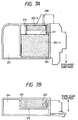
- This embodiment is different from the embodiment 1 as previously described in that the wide groove portion 216 (concavity) is provided at the upper portion of the ink communicating portion so that the lower portion or one end of the negative pressure generating member receiving portion on a partition wall 215 in the partition portion may be in communication with the ink communicating portion 206.
- the admission passage of the air into the ink storing portion can be easily secured upon the gas-liquid replacement which is made with the ink consumption.
- the ink supply from the ink storing portion in the ink communicating portion to the negative pressure generating member receiving portion can be stably maintained, and the ink level (gas-liquid interface) within the negative pressure generating member receiving portion can be retained substantially constant.
- the amount of ink received within the negative pressure, generating member receiving portion is substantially constant, and the variation in the ink supply or the negative pressure which may have effects on the recording quality can be suppressed.
- the ink level within the absorbing member receiving portion in supplying the ink from the ink storing portion to the absorbing member receiving portion is held at an appropriate position, until the ink is used up, so that the static negative Pressure within the absorbing member can be generated more stably.
- a recess portion 9 (concave) is provided in the bottom portion of the negative pressure generating member receiving portion, so that the bottom portion of the negative pressure generating member receiving portion is lower than the bottom portion of the negative pressure generating member receiving portion when mounting the ink jet cartridge.
- This recess portion 217 is provided to have the depth b in the area from the neighborhood of the ink communicating portion 206 to the neighborhood of the ink supply port 209, as shown in Fig. 12A.
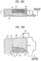
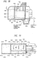
- an ink tank unit 1000 in this embodiment has a connecting opening portion 1101 as the ink supply port for supplying the ink to an ink jet head unit 2000 as the head portion on the bottom face of the ink tank unit 1000.
- the ink tank unit is comprised,substantially of a first accommodating chamber 1100 which is a negative pressure generating member receiving portion having an atmosphere communicating portion 1150 for receiving a negative pressure generating member 1102, a posterior second accommodating chamber 1200 for communicating to the bottom face of the first accommodating chamber 1100 through a minute communicating portion 1300 as the ink communicating portion and for storing the ink to be supplied to the first accommodating chamber 1100, and a lateral second accommodating chamber 1250 for communicating at partition walls 1251a and 1251b having a communicating portion larger than the minute communicating portion 1300 to the posterior second accommodating chamber 1200.
- an L-character shaped ink storing portion as in the previously described embodiment is formed by the posterior second accommodating chamber 1200 and the lateral second accommodating chamber 1250.
- the negative pressure, generating member 1102 is accommodated in the first accommodating chamber 1100 in two-thirds region from the bottom face of the first accommodating chamber.
- an ink supply promoting structure 1120 having a portion slightly lower than its bottom face.
- the structure of this ink supply promoting structure 1120 will be detailed later.
- This structure is disposed for the purpose of eliminating the interruption of the ink from the minute communicating portion 1300 to the connecting surface of the ink discharge portion, but becomes extremely effective means when the proper negative pressure can not be obtained only by the adjustment of the height of the gas-liquid replacement promoting structure 1110. For example, this is effective when the connecting opening portion 1101 with the ink jet head unit 2000 is on the bottom face of the ink tank portion 1100, or when the distance from the minute communicating portion 1300 to the connecting opening portion 1101 is large, or both as in this embodiment shown in Figs. 2A and 2B.
- the depth of the ink supply promoting structure 1120 is 1.5 mm lower than tee bottom surface of the posterior second accommodating chamber 1200 and the lateral second accommodating chamber 1250, or the bottom surface of the minute communicating portion 1300, thereby resolving all the previous problems.
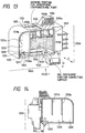
- 1600 is an ink tank unit housing
- 1102 is a negative pressure generating member
- 1400 is a vessel lid
- 1202a and 1202b are electrode pins for sensing the remaining amount of ink
- 1203 and 1204 are contact members extending from each electrode pin to electrode disposed in the ink discharge portion.
- 1206 is an ink pouring port
- 1205 is an ink pouring port plug.
- the ink tank unit housing 1600 is formed by integral molding of resin.
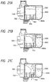
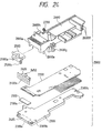
- a negative pressure generating member 1102 Within the first accommodating chamber 1100 of the ink tank unit housing 1600 is accommodated a negative pressure generating member 1102, which is inserted after compressed from both sides in the direction of the arrow of Figs. 21A to 21C.
- the negative pressure generating member 1102 is compressed to one-third to one-fourth the volume when accommodating it.
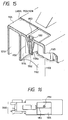
- 1610 and 2600f are a projection and a latch having spring property attached to the ink tank unit housing 1600 and the holder 2600, whereby the falling of the ink jet head unit can be prevented by engagement of both.
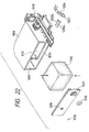
- Fig. 27 shows the assembling of a protective tape 3100 and a protection cap 3200 for protecting the discharge ports from drying and fixing or damage during physical distribution in packaging.
- the protection cap 3200 has a sponge 3220 in an area in contact with the discharge port face via the protective tape 3100, the protective tape 3100 being forced into contact with the discharge port face by a pressing force of 500 to 2000 g of this sponge.
- the protection cap 3200 has a projection 3210 engaging the holder 2600, while the holder 2600 has a depression caught by the projection on either side to prevent the falling by engagement of both.
- the case body 4100 is formed of a molding made of polypropylene from the aspects of impact durability, gas barrier property of preventing evaporation of the ink from the ink jet cartridge, as well as the costs.
- the case lid 4200 is formed, of a multi-layer film having excellent gas barrier property, for example, one in which a polyethylene terephthalate layer 12 ⁇ m, an aluminum evaporation layer 0.05 ⁇ m, a nylon layer 15 ⁇ m, a polyethylene layer 25 ⁇ m, an easy peel layer 25 ⁇ m are laminated in sequence from the outermost layer or the outside, or one in which a nylon 15 ⁇ m, an aluminum foil 9 ⁇ m and an easy peel layer 75 ⁇ m are laminated in sequence from the outermost layer.
- the packaging procedure is as follows.
- the buffer body 4300 After inserting the ink jet cartridge into the case body 4100, the buffer body 4300 is placed therein, a welding rib 4120 disposed in a flange portion 4110 of the case body 4100 and the easy peel layer of the case lid 4200 are welded together by heating to obtain a package.
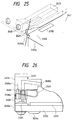
- Fig. 30 shows one embodiment of an ink jet recording apparatus having an ink jet cartridge mounted thereon according to the present invention.
- C is an ink jet cartridge of the present invention, as previously described, and 2 is a carriage for mounting for the movement four ink jet cartridges corresponding to four color inks of yellow, magenta, cyan and black.
- a recording medium 10 is supplied to a position opposite the discharge port face of the recording head, and fed via rollers 17, 18 into a paper exhaust portion when the recording is progressed.
- the blade 401 is a blade as the wiping member, one end thereof being held by a blade holding member to become a secured end, and taking a form of cantilever.
- the blade 401 is disposed at a position adjacent the recording area with the recording head, and in this embodiment, held in the projected form into the course of movement of the recording head.
- a discharge port recovery portion 500 is constituted of the blade 401, the cap 300 and the absorbing member 403, wherein the ink and the dirt sticking to the ink discharge port face can be removed by the blade 401 and the absorbing member 403.
- the cap 300 makes direct contact with the discharge port face of the ink jet cartridge to effect the capping, the cap 300 is moved to project into the course of movement of the cartridge.
- the cartridge C is moved from the home position to the start position of recording, the cap 300 and the blade 401 are located at the same position as in the wiping as above described. As a result, upon the movement before starting the recording, the discharge port face of the cartridge C is wiped.
- the recording system of the on demand type is especially effective.
- discharging the liquid (ink) through an opening for discharging by growth and shrinkage of the bubble at least one droplet is formed.
- growth and shrinkage of the bubbles can be effected instantly and adequately to accomplish more preferably discharging of the liquid (ink) particularly excellent in response characteristic.
- the constitution of the recording head in addition to the combination of the discharging port, liquid channel, and electrothermal converter (linear liquid channel or right-angled liquid channel) as disclosed in the above-mentioned respective specifications, the constitution by use of U.S. Patent 4,558,333 and 4,459,600 disclosing the constitution having the heat acting portion arranged in the flexed region is also included in the present invention.
- the present invention can be also effectively made the constitution as disclosed in Japanese Laid-Open Patent Application No. 59-123670 which discloses the constitution using a slit common to a plurality of electrothermal converters as the discharging port of the electrothermal converter or Japanese Laid-Open Patent Application No. 59-138461 which discloses the consitution having the opening for absorbing pressure wave of heat energy correspondent to the discharging portion.
- the present invention is extremely effective for not only the recording mode only of a primary color such as black, etc., but also a device equipped with at least one plural different colors or full color by color mixing, whether the recording head may be either integrally constituted or combined in plural number.
- the atmosphere communicating port of the negative pressure generating member receiving portion of the ink tank and the ink supply port are disposed on the opposed surfaces, with the atmosphere communicating port located above the ink supply port, the state where no ink resides near the atmosphere communicating port even with the ink accumulated near the ink supply port is easy to hold, and the ink leakage is less likely to occur.
- the exfoliation or distortion at the angled portion of the negative pressure generating member can be suppressed in inserting the negative pressure generating member, resulting in no gap between the ink storing portion and the negative pressure generating member, whereby the ink is concentrated in the neighborhood of the ink supply port, without the ink flowing near the atmosphere communicating port located upward, and ink leakage can be prevented beforehand.
- the ink supply to the recording head can be performed stably and highly reliably.
Landscapes
- Ink Jet (AREA)
- Pens And Brushes (AREA)
- Wet Developing In Electrophotography (AREA)
Applications Claiming Priority (19)
| Application Number | Priority Date | Filing Date | Title |
|---|---|---|---|
| JP15949493 | 1993-06-29 | ||
| JP159494/93 | 1993-06-29 | ||
| JP15949493 | 1993-06-29 | ||
| JP161135/93 | 1993-06-30 | ||
| JP16113593 | 1993-06-30 | ||
| JP16179093 | 1993-06-30 | ||
| JP16179093 | 1993-06-30 | ||
| JP16113593 | 1993-06-30 | ||
| JP161790/93 | 1993-06-30 | ||
| JP19137993 | 1993-08-02 | ||
| JP19137993A JPH0740544A (ja) | 1993-08-02 | 1993-08-02 | インクジェット用インクカートリッジおよびインクジェット記録装置 |
| JP191379/93 | 1993-08-02 | ||
| JP219787/93 | 1993-09-03 | ||
| JP21978793A JP2931511B2 (ja) | 1993-09-03 | 1993-09-03 | ヘッドカートリッジおよびプリント装置 |
| JP21978793 | 1993-09-03 | ||
| JP12596594A JP3187652B2 (ja) | 1993-06-29 | 1994-06-08 | インクタンクユニット、該インクタンクユニットを有するインクジェットカートリッジ、及び該インクジェットカートリッジを有するインクジェット装置 |
| JP12596594 | 1994-06-08 | ||
| JP125965/94 | 1994-06-08 | ||
| EP94109973A EP0631874B1 (de) | 1993-06-29 | 1994-06-28 | Tintenbehälter, Tintenstrahlpatrone mit Tintenbehälter und Tintenstrahlgerät ausgestattet damit |
Related Parent Applications (2)
| Application Number | Title | Priority Date | Filing Date |
|---|---|---|---|
| EP94109973A Division EP0631874B1 (de) | 1993-06-29 | 1994-06-28 | Tintenbehälter, Tintenstrahlpatrone mit Tintenbehälter und Tintenstrahlgerät ausgestattet damit |
| EP94109973.1 Division | 1994-06-28 |
Publications (3)
| Publication Number | Publication Date |
|---|---|
| EP0805032A2 true EP0805032A2 (de) | 1997-11-05 |
| EP0805032A3 EP0805032A3 (de) | 1997-11-12 |
| EP0805032B1 EP0805032B1 (de) | 2002-10-23 |
Family
ID=27552682
Family Applications (5)
| Application Number | Title | Priority Date | Filing Date |
|---|---|---|---|
| EP97109850A Expired - Lifetime EP0805032B1 (de) | 1993-06-29 | 1994-06-28 | Behälter für Flüssigkeit, Tintenstrahlkassette mit diesem Behälter für Flüssigkeit und Tintenstrahlapparat mit dieser Tintenstrahlkassette |
| EP97109851A Expired - Lifetime EP0802056B1 (de) | 1993-06-29 | 1994-06-28 | Behälter für Flüssigkeit, Tintenstrahlkassette mit diesem Behälter für Flüssigkeit und Tintenstrahlapparat mit dieser Tintenstrahlkassette |
| EP97109855A Expired - Lifetime EP0805033B1 (de) | 1993-06-29 | 1994-06-28 | Behälter für Flüssigkeit, Tintenstrahlkassette mit diesem Behälter für Flüssigkeit und Tintenstrahlapparat mit dieser Tintenstrahlkassette |
| EP94109973A Expired - Lifetime EP0631874B1 (de) | 1993-06-29 | 1994-06-28 | Tintenbehälter, Tintenstrahlpatrone mit Tintenbehälter und Tintenstrahlgerät ausgestattet damit |
| EP97109852A Expired - Lifetime EP0802057B1 (de) | 1993-06-29 | 1994-06-28 | Behälter für Flüssigkeit, Tintenstrahlkassette mit diesem Behälter für Flüssigkeit und Tintenstrahlapparat mit dieser Tintenstrahlkassette |
Family Applications After (4)
| Application Number | Title | Priority Date | Filing Date |
|---|---|---|---|
| EP97109851A Expired - Lifetime EP0802056B1 (de) | 1993-06-29 | 1994-06-28 | Behälter für Flüssigkeit, Tintenstrahlkassette mit diesem Behälter für Flüssigkeit und Tintenstrahlapparat mit dieser Tintenstrahlkassette |
| EP97109855A Expired - Lifetime EP0805033B1 (de) | 1993-06-29 | 1994-06-28 | Behälter für Flüssigkeit, Tintenstrahlkassette mit diesem Behälter für Flüssigkeit und Tintenstrahlapparat mit dieser Tintenstrahlkassette |
| EP94109973A Expired - Lifetime EP0631874B1 (de) | 1993-06-29 | 1994-06-28 | Tintenbehälter, Tintenstrahlpatrone mit Tintenbehälter und Tintenstrahlgerät ausgestattet damit |
| EP97109852A Expired - Lifetime EP0802057B1 (de) | 1993-06-29 | 1994-06-28 | Behälter für Flüssigkeit, Tintenstrahlkassette mit diesem Behälter für Flüssigkeit und Tintenstrahlapparat mit dieser Tintenstrahlkassette |
Country Status (7)
| Country | Link |
|---|---|
| EP (5) | EP0805032B1 (de) |
| AT (5) | ATE226516T1 (de) |
| DE (5) | DE69431762T2 (de) |
| DK (2) | DK0805033T3 (de) |
| ES (4) | ES2138013T3 (de) |
| PT (2) | PT805032E (de) |
| SG (2) | SG87851A1 (de) |
Families Citing this family (35)
| Publication number | Priority date | Publication date | Assignee | Title |
|---|---|---|---|---|
| US6247803B1 (en) | 1983-10-13 | 2001-06-19 | Seiko Epson Corporation | Ink jet recording apparatus and method for replenishing ink in the tank cartridge |
| JP3513979B2 (ja) * | 1994-09-16 | 2004-03-31 | セイコーエプソン株式会社 | インクジェットプリンタ用インクカートリッジ |
| US6145974A (en) * | 1983-10-13 | 2000-11-14 | Seiko Epson Corporation | Ink-supplied printer head and ink container |
| US6276785B1 (en) | 1983-10-13 | 2001-08-21 | Seiko Epson Corporation | Ink-supplied printer head and ink container |
| US6474798B1 (en) | 1984-10-11 | 2002-11-05 | Seiko Epson Corporation | Ink supplied printer head and ink container |
| DE69430452T2 (de) * | 1993-05-21 | 2002-10-31 | Canon K.K., Tokio/Tokyo | Tintenkassette |
| US6286944B1 (en) | 1993-05-21 | 2001-09-11 | Canon Kabushiki Kaisha | Ink jet unit with cartridge having controlled ink flow |
| US6238042B1 (en) | 1994-09-16 | 2001-05-29 | Seiko Epson Corporation | Ink cartridge for ink jet printer and method of charging ink into said cartridge |
| JPH08174860A (ja) | 1994-10-26 | 1996-07-09 | Seiko Epson Corp | インクジェットプリンタ用インクカートリッジ |
| US5953030A (en) * | 1995-04-24 | 1999-09-14 | Canon Kabushiki Kaisha | Ink container with improved air venting structure |
| US5784087A (en) * | 1995-04-27 | 1998-07-21 | Owens-Illinois Closure Inc. | Liquid containment and dispensing device |
| US6132036A (en) * | 1995-09-14 | 2000-10-17 | Canon Kabushiki Kaisha | Ink tank, production process of ink tank and ink-jet printing apparatus |
| US6168266B1 (en) | 1995-09-29 | 2001-01-02 | Canon Kabushiki Kaisha | Ink tank cartridge, a manufacturing method thereof and a packaging structure of the ink tank cartridge |
| AU741182B2 (en) * | 1995-09-29 | 2001-11-22 | Canon Kabushiki Kaisha | An ink tank cartridge, a manufacturing method thereof and a packaging structure of the ink tank cartridge |
| JP3750138B2 (ja) | 1996-02-21 | 2006-03-01 | セイコーエプソン株式会社 | インクカートリッヂ |
| JPH10787A (ja) * | 1996-06-13 | 1998-01-06 | Minolta Co Ltd | インクカートリッジ |
| US5821964A (en) * | 1996-07-24 | 1998-10-13 | Dataproducts Corporation | Cartridge for supplying liquid to a print head |
| ATE251039T1 (de) * | 1996-11-15 | 2003-10-15 | Canon Kk | Behälter zum ausbringen von flüssigkeit |
| JPH10193633A (ja) * | 1997-01-13 | 1998-07-28 | Brother Ind Ltd | インクカートリッジ |
| JPH10250104A (ja) | 1997-03-12 | 1998-09-22 | Seiko Epson Corp | インクジェット式記録装置用インクカートリッジ、及びその製造方法 |
| JP4141523B2 (ja) | 1997-03-19 | 2008-08-27 | セイコーエプソン株式会社 | インク供給流路の弁装置 |
| US6132037A (en) * | 1997-09-03 | 2000-10-17 | Bartolome; Jordi | Storage container for inkjet cartridges having cleaning means and a method for storing inkjet cartridges |
| EP1300249B1 (de) * | 1998-03-30 | 2008-10-22 | Brother Kogyo Kabushiki Kaisha | Tintenpatrone und Verfahren zur Detektion der restlichen Tintenmenge |
| US6270207B1 (en) | 1998-03-30 | 2001-08-07 | Brother Kogyo Kabushiki Kaisha | Ink cartridge and remaining ink volume detection method |
| JP3278410B2 (ja) * | 1998-05-11 | 2002-04-30 | キヤノン株式会社 | 液体収納容器、該容器の製造方法、該容器のパッケージ、該容器と記録ヘッドとを一体化したインクジェットヘッドカートリッジ及び液体吐出記録装置 |
| ES2301888T5 (es) | 1998-07-15 | 2013-04-12 | Seiko Epson Corporation | Unidad de suministro de tinta |
| JP3331976B2 (ja) | 1998-07-30 | 2002-10-07 | カシオ計算機株式会社 | インクカートリッジ |
| EP0999060B1 (de) | 1998-10-27 | 2005-04-20 | Canon Kabushiki Kaisha | Kopfhalter, Kopfanordnung, Kopfkassette, Tintenstrahldrucker, und Verfahren zur Herstellung einer Kopfanordnung |
| ES2275603T5 (es) | 2000-10-20 | 2010-07-07 | Seiko Epson Corporation | Dispositivo de registro de inyeccion de tinta y cartucho de tinta. |
| KR100487976B1 (ko) | 2000-10-20 | 2005-05-10 | 세이코 엡슨 가부시키가이샤 | 잉크젯 기록 장치용 잉크 카트리지 |
| PT1481808E (pt) | 2000-10-20 | 2007-02-28 | Seiko Epson Corp | Cartucho de tinta |
| JP3809401B2 (ja) * | 2001-07-27 | 2006-08-16 | キヤノン株式会社 | インクタンク |
| JP3991853B2 (ja) | 2002-09-12 | 2007-10-17 | セイコーエプソン株式会社 | インクカートリッジ |
| DE102006003055B4 (de) * | 2006-01-20 | 2008-02-07 | Phoenix Contact Gmbh & Co. Kg | Tintentank |
| AR108306A1 (es) * | 2016-05-27 | 2018-08-08 | Sumitomo Chemical Co | Dispositivo de pulverización |
Family Cites Families (12)
| Publication number | Priority date | Publication date | Assignee | Title |
|---|---|---|---|---|
| IT1145242B (it) * | 1981-12-23 | 1986-11-05 | Olivetti & Co Spa | Testina di stampa a getto d inchiostro e relativa stampante seriale |
| US4771295B1 (en) * | 1986-07-01 | 1995-08-01 | Hewlett Packard Co | Thermal ink jet pen body construction having improved ink storage and feed capability |
| US4794409A (en) * | 1987-12-03 | 1988-12-27 | Hewlett-Packard Company | Ink jet pen having improved ink storage and distribution capabilities |
| ES2073535T3 (es) * | 1989-09-18 | 1995-08-16 | Canon Kk | Elemento de cubricion para un recipiente de tinta de un cartucho para un cabezal de impresion para un aparato de impresion por chorros de tinta. |
| EP0578331B1 (de) * | 1989-09-18 | 1997-12-29 | Canon Kabushiki Kaisha | Methode zum Füllen einer Tintenpatrone für Tintenstrahlaufzeichnungsgeräte |
| DE69031541T2 (de) * | 1989-10-20 | 1998-03-05 | Canon Kk | Farbstrahlgerät und Kassette mit Tintenvorratsbehälter auf diesem Gerät aufstellbar |
| DE4025319A1 (de) * | 1990-08-07 | 1992-02-13 | Siemens Ag | Tintendruckwerk und verfahren zum einmaligen befuellen des tintenvorratsbehaelters des tintendruckwerkes |
| JPH04156339A (ja) * | 1990-10-19 | 1992-05-28 | Fujitsu Ltd | インクカートリッジ |
| JPH04282256A (ja) * | 1991-03-12 | 1992-10-07 | Seiko Epson Corp | インクジェット記録装置 |
| JP2960235B2 (ja) * | 1991-11-12 | 1999-10-06 | キヤノン株式会社 | インク容器、これを用いた記録ヘッドユニットおよびこれを搭載する記録装置 |
| CA2100977C (en) * | 1992-07-24 | 2000-02-08 | Noribumi Koitabashi | Ink container, ink and ink jet recording apparatus using ink container |
| DE69430452T2 (de) * | 1993-05-21 | 2002-10-31 | Canon K.K., Tokio/Tokyo | Tintenkassette |
-
1994
- 1994-06-28 AT AT97109850T patent/ATE226516T1/de active
- 1994-06-28 AT AT97109851T patent/ATE228064T1/de not_active IP Right Cessation
- 1994-06-28 AT AT94109973T patent/ATE184544T1/de not_active IP Right Cessation
- 1994-06-28 ES ES94109973T patent/ES2138013T3/es not_active Expired - Lifetime
- 1994-06-28 DE DE69431762T patent/DE69431762T2/de not_active Expired - Lifetime
- 1994-06-28 AT AT97109852T patent/ATE226892T1/de not_active IP Right Cessation
- 1994-06-28 EP EP97109850A patent/EP0805032B1/de not_active Expired - Lifetime
- 1994-06-28 SG SG9905532A patent/SG87851A1/en unknown
- 1994-06-28 EP EP97109851A patent/EP0802056B1/de not_active Expired - Lifetime
- 1994-06-28 EP EP97109855A patent/EP0805033B1/de not_active Expired - Lifetime
- 1994-06-28 EP EP94109973A patent/EP0631874B1/de not_active Expired - Lifetime
- 1994-06-28 AT AT97109855T patent/ATE217261T1/de active
- 1994-06-28 DK DK97109855T patent/DK0805033T3/da active
- 1994-06-28 ES ES97109851T patent/ES2184925T3/es not_active Expired - Lifetime
- 1994-06-28 PT PT97109850T patent/PT805032E/pt unknown
- 1994-06-28 SG SG1996006780A patent/SG67330A1/en unknown
- 1994-06-28 EP EP97109852A patent/EP0802057B1/de not_active Expired - Lifetime
- 1994-06-28 ES ES97109850T patent/ES2184924T3/es not_active Expired - Lifetime
- 1994-06-28 ES ES97109855T patent/ES2176559T3/es not_active Expired - Lifetime
- 1994-06-28 DE DE69430589T patent/DE69430589T2/de not_active Expired - Lifetime
- 1994-06-28 DE DE69431605T patent/DE69431605T2/de not_active Expired - Lifetime
- 1994-06-28 PT PT97109855T patent/PT805033E/pt unknown
- 1994-06-28 DE DE69420624T patent/DE69420624T2/de not_active Expired - Lifetime
- 1994-06-28 DK DK97109850T patent/DK0805032T3/da active
- 1994-06-28 DE DE69431634T patent/DE69431634T2/de not_active Expired - Lifetime
Also Published As
Similar Documents
| Publication | Publication Date | Title |
|---|---|---|
| EP0805033B1 (de) | Behälter für Flüssigkeit, Tintenstrahlkassette mit diesem Behälter für Flüssigkeit und Tintenstrahlapparat mit dieser Tintenstrahlkassette | |
| US6206513B1 (en) | Ink tank unit, an ink jet cartridge having said ink tank unit and an ink jet apparatus having said ink jet cartridge | |
| US6058984A (en) | Method for filling liquid into liquid container with liquid chamber, and liquid filling apparatus | |
| EP0538842B1 (de) | Verfahren zur Herstellung eines Tintenstrahlaufzeichnungskopfes | |
| JP3833123B2 (ja) | 保管されたインクジェットヘッド、及びインクジェットヘッドの保管方法 | |
| KR0135399B1 (ko) | 잉크 유도 요소를 구비한 잉크 카트리지를 갖는 기록 유니트를 사용하는 잉크 제트 기록 장치 | |
| US6431696B1 (en) | Ink tank unit, an ink jet cartridge having said ink tank unit and an ink jet apparatus having said ink jet cartridge | |
| KR100235283B1 (ko) | 잉크제트 인쇄 시스템과 잉크제트 프린트 카트리지 충전방법 | |
| US6332675B1 (en) | Ink container, ink and ink jet recording apparatus using ink container | |
| US6471346B2 (en) | Liquid container for ink jet head | |
| EP0709210B1 (de) | Tintenstrahlschreiber mit einem Kapillaritätsgradient | |
| JP2931511B2 (ja) | ヘッドカートリッジおよびプリント装置 | |
| HK1004639B (en) | Liquid accommodating container, ink jet cartridge having said liquid accommodating container and ink jet apparatus having said ink jet cartridge | |
| HK1011663B (en) | An ink tank unit, an ink jet cartridge having said ink tank unit and an ink jet apparatus having said ink jet cartridge | |
| HK1004640B (en) | Liquid accommodating container, ink jet cartridge having said liquid accommodating container and ink jet apparatus having said ink jet cartridge | |
| JPH10193634A (ja) | 吐出用液体収容容器 | |
| JP3281263B2 (ja) | インクタンクおよび該インクタンクを具えたインクジェット記録装置 | |
| JP7672887B2 (ja) | 液体吐出ヘッドおよび液体吐出装置とそれらの製造方法 | |
| JPH07125239A (ja) | インクタンクユニット、該インクタンクユニットを有するインクジェットカートリッジ、及び該インクジェットカートリッジを有するインクジェット装置 | |
| CA2229871C (en) | Liquid container for ink jet head | |
| AU744996B2 (en) | Liquid container for ink jet head | |
| JPH06191051A (ja) | インクジェット記録装置,該装置用インクタンクおよびインクタンク一体型記録ヘッドカートリッジ | |
| JPH03248847A (ja) | インクジェット記録装置 |
Legal Events
| Date | Code | Title | Description |
|---|---|---|---|
| PUAI | Public reference made under article 153(3) epc to a published international application that has entered the european phase |
Free format text: ORIGINAL CODE: 0009012 |
|
| PUAL | Search report despatched |
Free format text: ORIGINAL CODE: 0009013 |
|
| AC | Divisional application: reference to earlier application |
Ref document number: 631874 Country of ref document: EP |
|
| AK | Designated contracting states |
Kind code of ref document: A2 Designated state(s): AT BE CH DE DK ES FR GB GR IE IT LI LU NL PT SE |
|
| AK | Designated contracting states |
Kind code of ref document: A3 Designated state(s): AT BE CH DE DK ES FR GB GR IE IT LI LU NL PT SE |
|
| 17P | Request for examination filed |
Effective date: 19980330 |
|
| 17Q | First examination report despatched |
Effective date: 19991008 |
|
| RTI1 | Title (correction) |
Free format text: LIQUID ACCOMMODATING CONTAINER, INK JET CARTRIDGE HAVING SAID LIQUID ACCOMMODATING CONTAINER AND INK JET APPARATUS HAVING SAID INK JET CARTRIDGE |
|
| GRAG | Despatch of communication of intention to grant |
Free format text: ORIGINAL CODE: EPIDOS AGRA |
|
| GRAG | Despatch of communication of intention to grant |
Free format text: ORIGINAL CODE: EPIDOS AGRA |
|
| GRAH | Despatch of communication of intention to grant a patent |
Free format text: ORIGINAL CODE: EPIDOS IGRA |
|
| GRAH | Despatch of communication of intention to grant a patent |
Free format text: ORIGINAL CODE: EPIDOS IGRA |
|
| GRAA | (expected) grant |
Free format text: ORIGINAL CODE: 0009210 |
|
| AC | Divisional application: reference to earlier application |
Ref document number: 631874 Country of ref document: EP |
|
| AK | Designated contracting states |
Kind code of ref document: B1 Designated state(s): AT BE CH DE DK ES FR GB GR IE IT LI LU NL PT SE |
|
| REF | Corresponds to: |
Ref document number: 226516 Country of ref document: AT Date of ref document: 20021115 Kind code of ref document: T |
|
| REG | Reference to a national code |
Ref country code: GB Ref legal event code: FG4D |
|
| REG | Reference to a national code |
Ref country code: CH Ref legal event code: NV Representative=s name: BOVARD AG PATENTANWAELTE Ref country code: CH Ref legal event code: EP |
|
| REG | Reference to a national code |
Ref country code: IE Ref legal event code: FG4D |
|
| REG | Reference to a national code |
Ref country code: DK Ref legal event code: T3 |
|
| REF | Corresponds to: |
Ref document number: 69431605 Country of ref document: DE Date of ref document: 20021128 |
|
| REG | Reference to a national code |
Ref country code: GR Ref legal event code: EP Ref document number: 20030400051 Country of ref document: GR |
|
| REG | Reference to a national code |
Ref country code: PT Ref legal event code: SC4A Free format text: AVAILABILITY OF NATIONAL TRANSLATION Effective date: 20030113 |
|
| REG | Reference to a national code |
Ref country code: ES Ref legal event code: FG2A Ref document number: 2184924 Country of ref document: ES Kind code of ref document: T3 |
|
| ET | Fr: translation filed | ||
| PLBE | No opposition filed within time limit |
Free format text: ORIGINAL CODE: 0009261 |
|
| STAA | Information on the status of an ep patent application or granted ep patent |
Free format text: STATUS: NO OPPOSITION FILED WITHIN TIME LIMIT |
|
| 26N | No opposition filed |
Effective date: 20030724 |
|
| REG | Reference to a national code |
Ref country code: CH Ref legal event code: PFA Owner name: CANON KABUSHIKI KAISHA Free format text: CANON KABUSHIKI KAISHA#30-2, 3-CHOME, SHIMOMARUKO, OHTA-KU#TOKYO (JP) -TRANSFER TO- CANON KABUSHIKI KAISHA#30-2, 3-CHOME, SHIMOMARUKO, OHTA-KU#TOKYO (JP) |
|
| PGFP | Annual fee paid to national office [announced via postgrant information from national office to epo] |
Ref country code: LU Payment date: 20110708 Year of fee payment: 18 |
|
| PGFP | Annual fee paid to national office [announced via postgrant information from national office to epo] |
Ref country code: IE Payment date: 20120501 Year of fee payment: 19 Ref country code: DE Payment date: 20120630 Year of fee payment: 19 Ref country code: DK Payment date: 20120503 Year of fee payment: 19 Ref country code: NL Payment date: 20120620 Year of fee payment: 19 Ref country code: CH Payment date: 20120618 Year of fee payment: 19 |
|
| PGFP | Annual fee paid to national office [announced via postgrant information from national office to epo] |
Ref country code: GR Payment date: 20120605 Year of fee payment: 19 Ref country code: GB Payment date: 20120626 Year of fee payment: 19 Ref country code: SE Payment date: 20120503 Year of fee payment: 19 |
|
| PGFP | Annual fee paid to national office [announced via postgrant information from national office to epo] |
Ref country code: IT Payment date: 20120611 Year of fee payment: 19 |
|
| PGFP | Annual fee paid to national office [announced via postgrant information from national office to epo] |
Ref country code: ES Payment date: 20120626 Year of fee payment: 19 Ref country code: FR Payment date: 20120712 Year of fee payment: 19 |
|
| PGFP | Annual fee paid to national office [announced via postgrant information from national office to epo] |
Ref country code: PT Payment date: 20120523 Year of fee payment: 19 |
|
| PGFP | Annual fee paid to national office [announced via postgrant information from national office to epo] |
Ref country code: AT Payment date: 20120613 Year of fee payment: 19 |
|
| PGFP | Annual fee paid to national office [announced via postgrant information from national office to epo] |
Ref country code: BE Payment date: 20130409 Year of fee payment: 20 |
|
| REG | Reference to a national code |
Ref country code: PT Ref legal event code: MM4A Free format text: LAPSE DUE TO NON-PAYMENT OF FEES Effective date: 20131230 |
|
| REG | Reference to a national code |
Ref country code: NL Ref legal event code: V1 Effective date: 20140101 |
|
| PG25 | Lapsed in a contracting state [announced via postgrant information from national office to epo] |
Ref country code: PT Free format text: LAPSE BECAUSE OF NON-PAYMENT OF DUE FEES Effective date: 20131230 Ref country code: SE Free format text: LAPSE BECAUSE OF NON-PAYMENT OF DUE FEES Effective date: 20130629 |
|
| REG | Reference to a national code |
Ref country code: CH Ref legal event code: PL |
|
| REG | Reference to a national code |
Ref country code: SE Ref legal event code: EUG |
|
| REG | Reference to a national code |
Ref country code: DK Ref legal event code: EBP Effective date: 20130630 |
|
| REG | Reference to a national code |
Ref country code: AT Ref legal event code: MM01 Ref document number: 226516 Country of ref document: AT Kind code of ref document: T Effective date: 20130628 |
|
| GBPC | Gb: european patent ceased through non-payment of renewal fee |
Effective date: 20130628 |
|
| REG | Reference to a national code |
Ref country code: GR Ref legal event code: ML Ref document number: 20030400051 Country of ref document: GR Effective date: 20140103 |
|
| REG | Reference to a national code |
Ref country code: IE Ref legal event code: MM4A |
|
| REG | Reference to a national code |
Ref country code: DE Ref legal event code: R119 Ref document number: 69431605 Country of ref document: DE Effective date: 20140101 |
|
| REG | Reference to a national code |
Ref country code: FR Ref legal event code: ST Effective date: 20140228 |
|
| PG25 | Lapsed in a contracting state [announced via postgrant information from national office to epo] |
Ref country code: LI Free format text: LAPSE BECAUSE OF NON-PAYMENT OF DUE FEES Effective date: 20130630 Ref country code: CH Free format text: LAPSE BECAUSE OF NON-PAYMENT OF DUE FEES Effective date: 20130630 Ref country code: GB Free format text: LAPSE BECAUSE OF NON-PAYMENT OF DUE FEES Effective date: 20130628 Ref country code: DE Free format text: LAPSE BECAUSE OF NON-PAYMENT OF DUE FEES Effective date: 20140101 Ref country code: IE Free format text: LAPSE BECAUSE OF NON-PAYMENT OF DUE FEES Effective date: 20130628 Ref country code: NL Free format text: LAPSE BECAUSE OF NON-PAYMENT OF DUE FEES Effective date: 20140101 |
|
| PG25 | Lapsed in a contracting state [announced via postgrant information from national office to epo] |
Ref country code: FR Free format text: LAPSE BECAUSE OF NON-PAYMENT OF DUE FEES Effective date: 20130701 Ref country code: GR Free format text: LAPSE BECAUSE OF NON-PAYMENT OF DUE FEES Effective date: 20140103 Ref country code: AT Free format text: LAPSE BECAUSE OF NON-PAYMENT OF DUE FEES Effective date: 20130628 Ref country code: IT Free format text: LAPSE BECAUSE OF NON-PAYMENT OF DUE FEES Effective date: 20130628 |
|
| BE20 | Be: patent expired |
Owner name: *CANON K.K. Effective date: 20140628 |
|
| REG | Reference to a national code |
Ref country code: ES Ref legal event code: FD2A Effective date: 20140707 |
|
| REG | Reference to a national code |
Ref country code: PT Ref legal event code: MM4A Free format text: MAXIMUM VALIDITY LIMIT REACHED Effective date: 20140628 |
|
| PG25 | Lapsed in a contracting state [announced via postgrant information from national office to epo] |
Ref country code: DK Free format text: LAPSE BECAUSE OF NON-PAYMENT OF DUE FEES Effective date: 20130630 |
|
| PG25 | Lapsed in a contracting state [announced via postgrant information from national office to epo] |
Ref country code: ES Free format text: LAPSE BECAUSE OF NON-PAYMENT OF DUE FEES Effective date: 20130629 |
|
| PG25 | Lapsed in a contracting state [announced via postgrant information from national office to epo] |
Ref country code: PT Free format text: LAPSE BECAUSE OF EXPIRATION OF PROTECTION Effective date: 20140708 |
|
| PG25 | Lapsed in a contracting state [announced via postgrant information from national office to epo] |
Ref country code: LU Free format text: LAPSE BECAUSE OF NON-PAYMENT OF DUE FEES Effective date: 20130628 Ref country code: PT Free format text: LAPSE BECAUSE OF EXPIRATION OF PROTECTION Effective date: 20140108 |