EP0804981B1 - Procede de coulage continu et appareil s'y rapportant - Google Patents
Procede de coulage continu et appareil s'y rapportant Download PDFInfo
- Publication number
- EP0804981B1 EP0804981B1 EP96933649A EP96933649A EP0804981B1 EP 0804981 B1 EP0804981 B1 EP 0804981B1 EP 96933649 A EP96933649 A EP 96933649A EP 96933649 A EP96933649 A EP 96933649A EP 0804981 B1 EP0804981 B1 EP 0804981B1
- Authority
- EP
- European Patent Office
- Prior art keywords
- reduction
- roll
- target
- thickness
- pressure
- Prior art date
- Legal status (The legal status is an assumption and is not a legal conclusion. Google has not performed a legal analysis and makes no representation as to the accuracy of the status listed.)
- Expired - Lifetime
Links
Images


Classifications
-
- B—PERFORMING OPERATIONS; TRANSPORTING
- B22—CASTING; POWDER METALLURGY
- B22D—CASTING OF METALS; CASTING OF OTHER SUBSTANCES BY THE SAME PROCESSES OR DEVICES
- B22D11/00—Continuous casting of metals, i.e. casting in indefinite lengths
- B22D11/12—Accessories for subsequent treating or working cast stock in situ
- B22D11/1206—Accessories for subsequent treating or working cast stock in situ for plastic shaping of strands
Definitions
- the present invention relates to a continuous casting method and an apparatus therefor in which a cast slab is continuously withdrawn from a mold, and more particularly one in which a cast slab having a liquid core is subjected to reduction so as to produce a thin cast slab.
- a typical method of producing a thin plate includes rolling and forming in a rolling step.
- this type of method it is necessary before application of hot rolling to reheat a cast slab which has once cooled after casting. This process is disadvantageous from the viewpoint of energy consumption.
- a direct hot rolling method has been under development.
- a cast slab obtained from a continuous casting machine is directly supplied to a rolling mill.
- many attempts have been made to develop a continuous casting method which can produce cast slabs with rough hot rolling being omitted in the direct hot rolling process.
- Japanese Patent Publication No. 6-28790/1994 discloses a method of reducing the thickness of cast slabs having a liquid core with pairs of reduction rolls. According to this method, a series of spacers each having a different thickness are inserted between each pair of rolls to produce a cast slab having a target thickness by means of an arrangement in which the thickness of spacers gradually increases for downstream pairs of rolls and the roll gaps between the pairs of rolls gradually decrease for downstream pairs of rolls. Cast slabs are subjected to a reduction force corresponding to roll gaps in each of which spacers are inserted.
- Japanese Patent Publication No.6-28789/1994 discloses a method of carrying out casting by applying to each pair of rolls a reduction force which is increased depending on the time required until an unsolidified cast slab withdrawn from a mold reaches respective reduction rolls so that a given amount of roll reduction may be applied to the cast slab before finishing the roll reduction.
- An object of the present invention is to provide a continuous casting method and an apparatus for carrying out the method, according to which cast slabs having a desired thickness can be produced with great precision, and also cast slabs having a uniform internal structure free from segregation of impurities in the central area of the slabs can be produced.
- Another object of the present invention is to provide a continuous casting method and an apparatus therefor, in which cast slabs free from internal cracking having a uniform internal structure can be produced with great precision even when the roll gap is increased or decreased.
- the present invention is a process for continuously casting slabs, which comprises supplying cast slabs continuously withdrawn from a mold to a plurality of reduction devices arranged in tandem, providing a target roll gap, i.e., a roll reduction or target pressure to each of the reduction device, and performing roll reduction of a liquid core with the target roll gap and target pressure capable of being achieved for each of the reduction devices, characterized by selecting one of the plurality of reduction devices as a pivot reduction device, providing (assigning) a target roll gap to the pivot reduction device and each of the apparatuses upstream thereof, and providing (assigning) a target reduction force to each of the reduction devices downstream of the pivot reduction device.
- a target roll gap i.e., a roll reduction or target pressure
- a target roll gap is set so that the thickness of cast slabs is smaller than the thickness of the mold.
- the thickness of cast slabs is changed to be larger than before during continuous casting, i.e., when the roll gap increases, the thickness of cast slabs being subjected to reduction of a liquid core is restored to a target valve which is equal to or smaller than that of a mold.
- the present invention is a continuous casting apparatus in which cast slabs continuously withdrawn from a mold are supplied to a plurality of reduction devices arranged in tandem, a target roll gap or target pressure is provided (assigned) to each of the reduction device, and roll reduction of a liquid core with the target roll gap or target pressure being able to be achieved for each of the reduction devices is performed, characterized by comprising a means of selecting any one of the plurality of reduction devices as a pivot reduction device, means for providing (assigning) a target roll gap to the pivot reduction device and each of the apparatuses upstream thereof, and means for providing (assigning) a target reduction force to each of the reduction devices downstream of the pivot reduction device.
- the apparatus of the present invention further comprises means for providing a roll gap smaller than the thickness of the mold based on the means for providing a target roll gap, when a roll gap is decreased, i.e., cast slabs having a thickness smaller than that of the mold are produced.
- the apparatus of the present invention further comprises means for providing a roll gap larger than that being used, based on said means for providing a target roll gap, when the roll gap increases, i.e., when the thickness of cast slabs is changed to be larger than before during continuous casting (hereunder sometimes merely referred to as "release of roll gap").
- a cast slab continuously withdrawn from a mold with a solidified shell surrounding a liquid core is supplied to a plurality of reduction devices arranged in tandem.
- the cast slab goes downstream toward the reduction device, the cast slab is cooled, and an unsolidified portion thereof is gradually solidified with an increase in thickness of the solidified shell.
- a position of a cast slab from the mold where the thickness of the solidified shell reaches a target one is calculated, for example, by using equation (2) to be described later or based on the thermal conductivity in a manner described in Figure 13 to be explained later.
- a reduction device which is disposed at a position closest to the calculated position of the cast slab is selected as a pivot reduction device.
- a predetermined pivot reduction device is provided with a roll gap corresponding to a difference between the thickness of the cast slab at the exit of the mold and a target thickness thereof and each of the reduction devices upstream of the reference one is provided with a target roll gap calculated by multiplying the difference by a certain ratio so that cast slabs can be reduced with respect to their thickness gradually at an appropriate proportion through a first half group of the reduction devices including the pivot reduction device. It is possible, therefore, to set any desired target thickness, i.e., roll gap, and to carry out reduction to obtain such a predetermined target thickness of cast slabs.
- each reduction device downstream of the pivot reduction device is provided with a target pressure calculated on the basis of a reaction force previously determined based on the type of steel and on an iron static pressure of the cast slab at the position of the corresponding reduction device.
- Reduction through a second half group of reduction devices is carried out so that the target pressure can be maintained in each of the reduction devices.
- the iron static pressure can be calculated based on the density of the cast slab, a height from the reduction device to a meniscus, etc.
- the reaction force can be set, as described before, depending on the type of cast slab. It is possible, therefore, to prevent occurrence of a variation of thickness of cast slabs, which is sometimes caused by assignment of an unsuitable reaction force to a cast slab.
- a target roll gap is assigned to the pivot reduction device and a first group of reduction devices upstream thereof, and a target pressure is assigned to a second group of reduction devices downstream of the pivot reduction device. It is possible to perform roll gap control and roll pressure control simultaneously to produce thin cast slabs having a predetermined thickness free from a variation in thickness which is caused by assignment of an unsuitable reaction force.
- a reduction device which is used as the reference one before is taken as the pivot reduction device.
- the pivot reduction device is provided with a target roll gap corresponding to a difference between the thickness of the cast slab after reduction in the preceding operation, i.e., the present roll gap, and a new target thickness thereof, and the reference reduction and each of the reduction devices upstream of the reference one as provided with an increased target roll gap calculated by multiplying the difference by a certain ratio so that cast slabs can be reduced with respect to their thickness gradually at an appropriate proportion through a first group of the reduction devices including the pivot reduction device. It is possible, therefore, to set any desired target thickness, i.e., roll gap, and to carry out reduction to obtain cast slabs having an increased target thickness.
- each of the reduction devices downstream of the reference device is provided with a target pressure calculated on the basis of a reaction force previously determined based on the type of steel and the iron static pressure of the cast slab at the position of the corresponding reduction device.
- the target pressure is set to be larger than the iron static pressure by a certain degree.
- the iron static pressure can be calculated based on the density of the cast slab, the height from the reduction device to a meniscus, etc.
- the reaction force can be set, as described before, depending on the type of steel. It is possible, therefore, to prevent variation in the thickness of cast slabs, which is sometimes caused by assignment of an unsuitable reaction force to a cast slab.
- a target roll gap is assigned to the pivot reduction device and the first group of reduction devices upstream of the pivot reduction device, and a target pressure is assigned to the second group of reduction devices downstream of the pivot reduction device. It is possible to perform roll gap control and roll pressure control simultaneously to produce thin cast slabs having a predetermined thickness free from a variation in thickness which is caused by assignment of an unsuitable reaction force.
- the thickness of a cast slab at the exit of the pivot reduction device is determined on the basis of a value detected by a thickness meter, or on the basis of a roll gap of the reduction device next to the pivot reduction device on the downstream side.
- the determined thickness is smaller than the target thickness, it is judged that the thickness of the unsolidified portion of the slab is excessively large, and in place of the present pivot reduction device, the reduction device next to the pivot reduction one on the downstream side is made a new pivot reduction device.
- the roll gap is detected for the pivot reduction device.
- a pivot reduction device is always suitably selected.
- the direction of pressure applied to a hydraulic double-acting cylinder is determined based on whether the values detected by the roll gap detector and a difference from the target roll gap are positive or negative.
- a pressure corresponding to the difference may be made a target pressure, and the degree of opening of a pressure control valve can be adjusted on the basis of the target pressure and a value detected by a pressure meter.
- the pressure control valve is operated such that a predetermined degree of opening is achieved, and the switching valve is operated such that a predetermined direction of pressure is achieved.
- the roll gap of each of the reduction devices can be adjusted to respective target roll gaps by operating the switching valve and pressure control valve.
- the degree of opening of the pressure control valve is determined on the basis of an assigned target pressure and a pressure detected by a pressure gauge, and pressure control is carried out by adjusting the pressure control valve so as to achieve the determined degree of opening.
- the present invention provides a continuous casting method for producing thin cast slabs by applying liquid core reduction in a roll reduction zone, characterized in that the roll reduction force is released in such a way that a rate of increase of the final roll gap is satisfied by the following equation, which determines the target roll gap, when the thickness of cast slabs is returned to a thickness smaller than the original thickness of the cast slab before application of roll reduction.
- V R ⁇ (V R ) Cr ⁇ Cr 5L 2 V C 9DL S ⁇ 10 -4
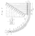
- Figure 1 is a diagrammatic illustration of a bent-type continuous casting machine for producing slabs of the present invention.
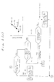
- Figure 2 is a diagrammatic illustration of a control system for a drive mechanism of a reduction device.
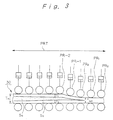
- Figure 3 is a sectional side view of a cast slab having a liquid core which is supplied to a roll reduction zone.
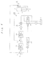
- Figure 4 is a block diagram showing a control logic for a pivot reduction roll and reduction rolls upstream thereof.
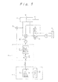
- Figure 5 is a block diagram showing a control logic for reduction rolls downstream of the pivot reduction roll.
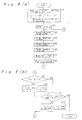
- Figures 6a, 6b, and 6c are flow charts describing processes for calculating a target roll gap and a target pressure, and for determining a pivot reduction roll, respectively.
- Figure 7 is a diagrammatic illustration of a reduction device for cast slabs having a liquid core, which is employed by the present invention.
- Figure 8 is an illustration showing the occurrence of clearance between the cast slab and supporting rolls during releasing roll reduction.
- Figure 9 is an illustration showing the occurrence of bulging deformation caused by clearance between the cast slab and supporting rolls during releasing roll reduction.
- Figure 10 is a graph showing the amount of bulging as a function of time during releasing roll reduction.
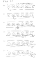
- Figures 11a through 11f are diagrammatic views showing releasing strains introduced into a cast slab having a liquid core by roll reduction while a portion of maximum bulging of the cast slab is passing from one segment of the roll reduction zone to the next segment.
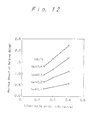
- Figure 12 is a graph showing the maximum amount of bulging db as a function of casting speed Vc for different reduction releasing speeds V R .
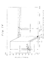
- Figures 13a and 13b are graphs showing results obtained by calculating the thickness of a solidified shell based on thermal conductivity.
- Figure 14 is a graph showing the thickness of a solidified shell and the thickness of a liquid core with respect to time at the position of the pivot reduction roll.
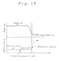
- Figure 15 is a graph showing results of a simulation of changing roll gap patterns during control of a roll gap.
- FIG. 1 is a diagrammatic illustration of a bent-type continuous casting machine for producing slabs.
- a ladle L in which a molten steel is contained is moved to above a tundish T.
- a sliding nozzle SN is provided at the bottom of the ladle L .
- a molten steel within the ladle L is passed into the tundish T and stored therein temporarily.
- a feed nozzle FN is disposed and extends into a mold M having a shape of a rectangular barrel.
- a molten metal introduced into the tundish T is kept there temporarily, and then the molten steel is poured into the mold M as a stable flow via the feed nozzle FN.
- the molten steel poured into the mold is cooled and withdrawn from the mold as cast slabs having a solidified shell surrounding a liquid core. Downstream of the mold M is provided a spray roll zone where cooling water is sprayed at the cast slab. In the spray roll zone, an unsolidified portion of the cast slab is further cooled (secondary cooling).
- a plurality of groups of roll zones GR 1 , GR 2 , GR 3 , GR 4 , and GR 5 , and a pinch roll zone PIR are arranged with a prescribed curvature so as to bend the cast slabs having a liquid core while moving them to a horizontal position.
- Cast slabs having a liquid core are disposed horizontally and then passed to a reduction roll zone PRT where the cast slabs are reduced with respect to their thickness by means of a plurality of reduction rolls PR which are arranged in tandem, and then further cooled while roll reduction is carried out to continuously produce cast slabs.
- a reduction roll PR, hydraulic cylinder 3, and piston rod 4 make up a reduction device.
- a plurality of reduction controllers 2, each of which controls reduction movement of each of the reduction devices are provided with a target pressure or target roll gap from a reaction force/roll gap controller 1.
- the positions of pistons 4 and the pressure of cylinders 3 are controlled such that each of the reduction controller 2 is provided with an assigned target pressure or target reduction position.
- FIG. 2 is a diagrammatic illustration of a control system for driving a reduction device.
- Each of the reduction rolls PR has an upper roll 15 and a lower roll 16.
- double-acting hydraulic cylinders 3 are disposed with rods 5 of pistons 4 facing downward.
- the lower ends of the rods 5 are connected to respective ends of the upper roll 15.
- the upper roll 15 is provided with a predetermined roll gap or reduction pressure using the hydraulic cylinders 3, so the thickness of a cast slab S having a liquid core is reduced when it passes through the roll gap between the upper and lower rolls 15, 16.
- the hydraulic cylinder 3 comprises upper and lower chambers divided by a piston 4, and hydraulic piping 17, 18 connected to the chambers at one end thereof.
- piping 17 is connected via a motor-driven pressure control valve 10 to one port of a magnetic switching valve 8 of the 4 port-2 position type.
- Piping 18 is connected to another port of the switching valve 8.
- One of the remaining two ports of the switching valve 8 is connected via a pump P to an oil tank 7, and the other one is directly connected to the oil tank 7.
- the pressure control valve 10 is provided with piping 19 so as to return excess oil to the oil tank 7 during time period of reducing pressure.
- the oil pressure within the hydraulic cylinder 3 is adjusted by the pressure control valve 10.
- the hydraulic cylinder 3 has a roll gap detector 6.
- a roll gap detected by the detector 6 is provided to a reduction controller 2.
- a pressure meter 12 is disposed between the pressure control valve 10 of the piping 17 and the hydraulic cylinder 3 to detect the oil pressure which has been adjusted by the pressure control valve 10.
- a signal corresponding to the pressure detected by the pressure meter 12 is provided to the reduction controller 2.
- the reduction controller 2 is provided with a target pressure and target roll gap from the reaction force/roll gap controller 1 (see Figure 1), and the reduction controller 2 provides signals to change the opening or the position of the pressure control valve 10 and the switching valve 8, respectively, so that the detected values of the pressure meter 12 and the roll gap detector 6 will be the same as the target pressure and the target roll gap.
- the reaction force/reduction controller 1 can determine a target reduction pressure and a target roll gap in the following manner.
- Figure 3 is a sectional side view of a cast slab 30 having a liquid core which is supplied to a roll reduction zone PRT.
- the cast slab 30 supplied to the roll reduction zone PRT is cooled by air, and the thickness of a liquid core S G remaining in the center of the slab decreases gradually, and simultaneously, the thickness of a solidified shell S S surrounding the liquid core S G increases.
- the liquid core S G of the cast slab disappears.
- a pivot reduction roll PR o is selected from a plurality of reduction rolls PR, PR, ... in the reduction roll zone PRT of the reaction force/roll gap controller 1 in accordance with the following equations (1) and (2). Namely, the pivot reduction roll PR o is made the reduction roll which is closest to the position where the sum of the thickness T 1 of the solidified shell S S on the liquid core S G of the cast slab and the thickness T 2 of the solidified shell S G underneath the liquid core S G , i.e., T 1 + T 2 , is equal to a target thickness T ref .
- the position of the pivot reduction roll can be determined by calculation based on thermal conductivity. See the descriptions relating to Figure 13.
- the reaction force/reduction controller 1 also provides target reductions obtained by multiplying the difference ⁇ T by predetermined ratios for a certain number of reduction rolls PR 1 , PR -2 , .... upstream of the pivot reduction roll PR o .
- target pressure or reduction corresponding to a reduction of 1/3 ⁇ T is assigned to the reduction controller for reduction roll PR -1
- a value of 2/3 ⁇ T is assigned to reduction roll PR -2 .
- the amounts of 1/3 ⁇ T, 2/3 ⁇ T, and ⁇ t are indicated by S o .
- the reduction controller 2 can be controlled by the following manner based on S o .
- Figure 4 is a block diagram showing control logic for the pivot reduction roll and reduction rolls upstream thereof.
- the signal S o is provided to a first subtractor 21 of each of reduction controller 2 which control the pivot reduction roll and the reduction rolls upstream thereof.
- reduction data detected by the reduction detector 6 are also provided, and the first subtractor 21 outputs a value obtained by subtracting the detected reduction from S o to a pressure signal control unit 22.
- the first subtractor 21 provides the result of subtraction to a switching signal control unit 25.
- the switching signal control unit 25 depending on whether the resulting data are positive or negative, determines a direction of movement of the piston of the cylinder 3, forms a switching signal, and provides it to the switching valve 8.
- the before-mentioned pressure signal control unit 22 calculates by PID calculation a pressure signal corresponding to a difference from a predetermined reduction and provides the signal to a second subtractor 23.
- a hydraulic pressure which is adjusted by a pressure control valve 10 is supplied from the pressure meter 12.
- the second subtractor 23 outputs the difference between the pressure signal and the hydraulic pressure to the opening signal control unit 24.
- the opening signal control unit 24 calculates an opening signal corresponding to the difference by PID calculation and provides the result to the pressure control valve 10 to adjust the degree of opening and to control the reduction.
- the reaction force/reduction controller 1 shown in Figure 1, as shown in Figure 3, provides a substantial reaction force ⁇ and a target pressure (P i + ⁇ ) obtained from the following equation (3) to the reduction controllers 2 of the reduction rolls PR 1 , PR 2 , ... downstream of the pivot reduction roll PR o .
- the substantial reaction force ⁇ is varied depending on the type of steel, and the reaction force/reduction controller 1 stores specific values of ⁇ for respective types of steel.
- P i (P o x S)/A wherein
- FIG. 5 is a block diagram showing a control logic for reduction rolls downstream of the pivot reduction roll PR o .
- the reaction force/reduction controller 1 has an ⁇ table 32 which includes data of ⁇ respective for a variety of steels.
- a target pressure calculating unit 31 reads the data of ⁇ for the steel being processed from the ⁇ table 32, calculates the target pressure (P 1 + ⁇ ) in accordance with equation (3), and provides the resulting data to a subtractor 26 of the reduction controller 2 which controls the reduction rolls downstream of the pivot reduction roll.
- the hydraulic pressure which is supplied to the hydraulic cylinder 3 is provided by the pressure meter 12.
- the hydraulic cylinder 3 is operated at a force f determined in accordance with the following equation (4).
- the subtractor 26 provides a difference between the target pressure (P 1 + ⁇ ) and a hydraulic pressure detected by the pressure meter 12 to the opening signal control unit 27.
- f (P 1 + ⁇ ) x A
- the opening signal control unit 27 generates an opening signal corresponding to the determined difference and provides it to a pressure control valve 10 to adjust the degree of opening so that the reduction by the hydraulic cylinder 3 can be controlled.
- a reduction corresponding to the reaction force is applied to the cast slab, and cast slabs having a target thickness can be produced with high precision.
- the reaction force/reduction controller 1 can shift the position of the pivot reduction roll PR o as follows.
- the reaction force/reduction controller 1 When the thickness of a liquid core is larger than ⁇ T, since the actual reduction at the pivot reduction roll PR o is ⁇ T - ⁇ and a large reaction force is produced, the reaction force/reduction controller 1, based on the reduction detected by the reduction detecting device 6 disposed on the pivot reduction roll PR o , shifts the position of the pivot reduction roll PR o to the roll just upstream of the previous pivot reduction roll if the actual reduction is equal to ⁇ T - ⁇ . The reaction force/reduction controller 1 repeatedly shifts the position of the pivot reduction roll PR o until the actual reduction is equal to ⁇ T.
- the reaction force/reduction controller 1 When the position of the pivot reduction roll PR o is changed, the reaction force/reduction controller 1 provides a target reduction and a target pressure which can result in the same reduction as that previously determined to the reduction rolls PR -1 , PR -2 , .... upstream of the pivot reduction roll PR o after correction, and to the reduction rolls PR 1 , PR 2 , ..., downstream of the pivot reduction roll PR o .
- One method is to select it in accordance with a roll reduction detected by a series of steps S1 through S12 shown in Figure 6a through Figure 6c , and the other is to select it on the basis of reaction forces.
- Figures 6a through 6c are flow charts describing processes for calculating a target roll reduction and a target pressure and for selecting the pivot reduction roll in the reaction force/reduction controller 1.
- the reaction force/reduction controller 1 is provided with a target thickness T ref of cast slabs.
- a pivot reduction roll PR o is selected from the reduction rolls of the reduction roll zone PRT in accordance with the before-described equations (1) and (2) such that the thickness (T 1 +T 2 ) of the solidified shell S S of the cast slab having a liquid core is equal to the target thickness T ref (Step S 1 ).
- the reaction force/reduction controller 1 is also provided with data of substantial reaction force ⁇ for each type of steel, and the reaction force/reduction controller I chooses a specific value of ⁇ for the steel being processed (Step S 2 ).
- the resulting value of ⁇ T i.e., a target reduction is provided to the reduction controllers 2 of the pivot reduction roll PR o (Step S 4 ).
- the reaction force/reduction controller 1 assigns target reductions calculated by multiplying the difference ⁇ T by 1/3 and 2/3, respectively, i.e., 1/3 ⁇ T and 2/3 ⁇ T to the two reduction rolls upstream of the pivot reduction roll PR o (Steps S 3 , S 4 ).
- the reaction force/reduction controller 1 calculates a target pressure (P i + ⁇ ) on the basis of the selected value for ⁇ and the before-described equation (3) (Step S 5 ), and the resulting target pressure (P i + ⁇ ) is provided to each of the reduction controllers 2 of the reduction rolls PR 1 , PR 2 , ... downstream of the pivot reduction roll PR o . (Step S 6 ).
- the reaction force/reduction controller 1 reads detected data of the reduction detectors 6 fixed to the reduction roll PR 1 downstream of the pivot reduction roll PR o (Step S 7 ).
- the distance between the upper and lower rolls of the reduction roll PR 1 , which is detected by the reduction detector 6, is taken as the thickness T out at the exit of the pivot reduction roll PR o (Step S 8 ).
- the reaction force/reduction controller 1 decides whether T out ⁇ T ref (Step S 9 ). When the inequality T out ⁇ T ref is not satisfied, the reaction force/reduction controller 1 decides to shift the position of the pivot reduction roll PR o to the next roll downstream (Step S 10 ) and returns to Step S 3 . See Figure 6a. This process is repeated until the inequality T out ⁇ T ref is satisfied in Step S 9 .
- the reaction force/reduction controller 1 decides whether the actual reduction is equal to ⁇ T on the basis of the detected data of the reduction detector 6 fixed to the pivot reduction roll PR o (Step S 11 ). If it is not equal to ⁇ T, the pivot reduction roll PR o is made the next roll upstream at the time when the detected data reach ⁇ T - ⁇ (Step S 12 ), and Step S 3 is returned to. This process is repeated in the reaction force/reduction controller 1 until it is decided that the actual reduction is equal to ⁇ T in Step S 11 .
- the explanation above has been made with reference to the case in which the thickness of the cast slab is reduced.
- the target thickness T out-1 before change must be increased to a new target thickness T out-2 , where T out-2 ⁇ T in .
- the pivot reduction roll PR o before change is decided to be used as a new pivot reduction roll
- the reaction force/reduction controller calculates new target reductions each having an increase obtained by multiplying the before-described difference ⁇ T 2 by a given ratio, and provides them to each of a predetermined number of reduction rolls PR -1 , PR -2 , .... upstream of the pivot reduction roll PR o .
- the reduction controller of reduction roll PR -1 is provided with a target pressure and reduction having an increase of 1/3 ⁇ T 2
- the reduction controller of reduction roll PR -2 is provided with a target pressure and reduction having an increase of 2/3 ⁇ T 2 .
- the reduction controller 2 can be controlled using the value of S o in accordance with the control logic which is applicable to the pivot reduction roll and reduction rolls upstream thereof, as shown in Figure 4, for example. Furthermore, control of reaction force during reduction for the reduction rolls PR i downstream of the pivot reduction roll PR o and correction of the position of the pivot reduction roll can be done in the same manner as in the case of reduction of thickness.
- the reduction device is of the oil-actuated type, but in accordance with the present invention, in place of oil, other mediums may be used.
- the reduction device is actuated by a cylinder, but a screw jack, for example, may be used.
- the amount of strains introduced at the solidification interface during reduction of a cast slab having a liquid core is determined only by the amount of reduction, not by the reduction rate. As long as the amount of reduction is so small that no internal cracks occur, even if the reduction rate is increased to any degree, there will be no internal cracks during reduction to a target thickness. On the other hand, in the case of increasing a roll gap, if a releasing speed of the reduction is increased beyond a certain point, strains are newly introduced, causing internal cracks in accordance with the following mechanism.
- the clearance 45 first occurs at the exit roll of the segmented rolls, and it spreads to upstream rolls.
- Figure 9 illustrates the shape of a cast slab during release of reduction, in which a solidified shell S S receives a static pressure from a unsolidified portion S G , and at the position of the slab supporting roll PR, a deformation 46 due to bulging occurs to occupy the clearance.
- the deformation caused by bulging is hereunder called “bulging deformation” in order to distinguish it from general bulging occurring between rolls.
- the amount of bulging deformation can be defined by the difference (db) between the roll gap and a thickness of the cast slab at the edge portions thereof.
- Figure 10 shows the bulging deformation at the exit of the segmented reduction rolls when release of reduction of a cast slab having a liquid core is carried out using segmented rolls comprised of 5 supporting rolls, as in Figure 7.
- the bulging deformation occurs during the second half of release of reduction. The maximum is reached at the end of release of reduction.
- the time when the release of reduction is finished is the point when an unsolidified portion disappears and the roll gap at the exit of the segmented rolls reaches a target thickness. In the case illustrated in Figure 10, it was 50 seconds after the release was started. After the completion of release, the bulging deformation remains until the thickness of the edge portions of the slab reaches a target value, e.g., 90 mm in the case of Figure 10.
- a target value e.g. 90 mm
- the distance the cast slab passes in a time period from the beginning of the bulging deformation to the attainment of the maximum level thereof is equal to the length L S of the segmented rolls for carrying out liquid core reduction.
- the distance the cast slab passes in a time period from the maximum bulging deformation to the elimination of the bulging deformation is also equal to the length L S .
- the bulging deformation occurs at an exit roll of the segmented rolls (the 5th roll R 5 of Figure 7 in the case of Figure 10) at the time when a clearance is formed between a roll and the cast slab.
- the clearance is formed at roll 4 (R 4 ), roll 3 (R 3 ), and roll 2 (R 2 ) successively, corresponding to points 04, 03, and 02 in Figure 10, for example, and the bulging deformation increases.
- the clearance disappears gradually while the cast slab passes from roll 2 (R 2 ) through roll 5 (R 5 ) successively when the roll gap is equal to the thickness of the slab at its edge portions. See points C2, C3, C4, and C5 of Figure 10.
- Figures 11 shows the change in the shape of a cast slab when a portion of the slab where the maximum bulging deformation occurs at the exit of the segmented rolls is passing through the segmented rolls.
- the area of interest is cross-hatched. It is to be noted that Figure 11 does not illustrate an exact pass line of the segmented rolls, but illustrates a relative position between a solidified shell at the widthwise central portion of the slab and supporting rolls so as to clearly explain occurrence of bulging and roll reduction of the portion where the bulging occurs.
- Figures 11b through 11e show respective states when the noted portion 47 passes the 3rd roll (R 3 ), the 4th roll (R 4 ), and the 5th roll (R 5 ), which correspond to points 03 and 04 and the release finishing point of Figure 10, respectively.
- the releasing rate will be defined as a speed of raising an exit roll of the segmented groups of rolls for carrying out liquid core reduction, i.e., a liquid core reduction segment.
- a maximum bulging deformation db (mm) at the portion just below the exit roll of the liquid core reduction segment was determined at varied casting speeds Vc (m/min) and releasing rates V R (mm/S). The results of the determination are shown in Figure 12. Based on the results, the following relationship can be derived.
- db 18 x V R x L S /L c wherein L S stands for a distance between an inlet roll and an exit roll of the liquid core reduction segment, i.e., the length of the liquid core reduction segment.
- the maximum bulging db at the exit of the liquid core reduction segment is not affected by the amount of release of reduction, but is varied depending on the releasing rate, the casting speed, and the segment length.
- the amount of bulging becomes a maximum at a midpoint of the reduction releasing operation, as shown in Figure 10.
- the portion of the cast slab where the maximum db is formed is subjected, as illustrated in Figures 11(a) - 11(f), to introduction of the misalignment strains of the bulging type at an area between the 3rd roll and the 4th roll and then to reduction strains of the leveled type at the next roll.
- ⁇ bm 2.74 x (D ⁇ /L 2 ) x 100 (%)
- the noted portion 47 is subjected to introduction of the misalignment strains of the bulging type in an area between the 3rd roll (R 3 ) and the 4th roll (R 4 ). This is because the liquid core reduction segment contains five rolls. When the segment contains a different number of rolls, the location of the roll where the noted portion 47 suffers from misalignment strains of the bulging type is also changed. However, such a location is not important, since internal cracks are formed when the amount of strains introduced to a brittle area (usually an area of a solid phase ratio of 0.8 - 0.99) at the solidification interface of the solidified shell is increased beyond a critical amount.
- the internal cracks are formed at a time when a total amount of the introduced strains is over the critical amount.
- the maximum amount of bulging is the sum of the amounts of bulging deformation which the noted portion receives at each of the rolls.
- the amount of misalignment strains of the bulging type is proportional to the amount of bulging. At each of the rolls where bulging occurs, the amount of the misalignment strains of the bulging type is calculated and summed. The resulting total amount is equal to the amount of strains which are introduced by applying the maximum bulging at one time.
- strains caused by releasing the liquid core reduction are a total of the strains obtained by calculation using ⁇ of the equations (6) and (7) and the maximum bulging db, and can be described by the following equation.
- casting machines are designed such that the amount of the existing strains is at most 50% or less of the critical amount for internal cracks with a factor of safety being 1.4 or more, although the critical amount varies depending on the type of steel.
- the amount of strains caused by releasing the liquid core reduction ( ⁇ R ) is restricted to 50% or less of the critical amount for internal cracks, the occurrence of internal cracks can successfully be avoided during releasing of the liquid core reduction.
- ⁇ CR critical amount
- the roll pitch L (mm) can take different values within the liquid core reduction area to give a target reduction, it is advisable from the viewpoint of safety to use as a minimum roll pitch a distance from a roll nearest to the meniscus within the liquid core reduction rolls to the first roll which can provide a target pressure.
- the solidified shell thickness increases slightly in the liquid core reduction area where a target reduction is achieved, the solidified shell thickness at the exit of the liquid core reduction area can be used.
- the solidified shell thickness can be obtained by calculation or measurement.
- Le which means the distance (m) from the meniscus
- Le the distance from the meniscus to the final roll in the liquid core reduction area where a target reduction is achieved
- the above method is not affected by a reduction during liquid core reduction and is effective in a case where releasing is carried out after a small amount of reduction, i.e., slight reduction.
- the thickness of cast slabs is small in the continuous casting method employing liquid core reduction, and the solidification finishing position is rather near the meniscus compared with that after release of reduction, it is possible to advantageously increase production speed by increasing the casting speed. If such high speed of casting is continued after releasing is initiated, the solidification finishing position shifts outside the machine, resulting in bulging after leaving the machine. Marked deteriorations in inner quality and shape of products are inevitable. It is necessary, therefore, that the casting speed be within a range where the solidification finishing position can be kept within an area of the casting machine.
- This example specifically shows that control of roll reduction can easily be done depending on changes of operational conditions during the liquid core reduction operation.
- a simulation model was a one-dimensional model for a portion of 1/2 the thickness of the slab.
- the thickness of mold i.e., thickness of cast slab within the mold was 90 mm.
- the distance of cast slab from a molten metal level within the mold was shown with respect to the solidified shell thickness and temperature in Figures 13a and 13b, respectively. According to the results thereof, it is possible to determine a roll reduction position, i.e., reference position, where the thickness of the solidified shell was equal to a target thickness.
- the thickness of an unsolidified portion is small at the reduction roll position of the pivot reduction device, the thickness of the solidified shell is larger than the target thickness after reduction, even if the reduction is performed.
- an unsolidified portion remains at a pivot reduction roll which is selected by the automatic position control (APC) system, segregation can not be eliminated. Therefore it is desirable that the thickness of an unsolidified portion be substantially zero at the pivot reduction roll position.
- API automatic position control
- the most suitable roll position which was determined by APC was in Case B o exhibiting a solidification thickness B o and an unsolidification thickness B o .
- the reduction is substantially equal to the unsolidification thickness
- a finishing position i.e., the roll position of the pivot reduction device. If reaction force control is applied to the rolls downstream of the pivot roll, therefore, the slab thickness does not change but is 60 mm, a target thickness.
- the roll position is unsuitable in Case A. This is the case in which at a first position (a) of the roll to which APC is applied, the solidification thickness is small. When the roll reduction reaches 30 mm, an unsolidified portion still remains. If reaction force control is not applied to the rolls downstream, as shown in Case B 1 , a target slab thickness of 60 mm can be achieved, but an unsolidified portion is being cooled and solidified, resulting in no elimination of center line segregation.
- the slab thickness will be 60 mm or less just like the case shown as Case B 2 .
- Figure 15 shows results of simulation of an operation when a pattern of the roll position control (APC) is changed. Changes in roll reduction and reduction pressure are plotted with respect to time for a final roll to which the roll position control by APC is applied.
- API roll position control
- the reaction force during roll reduction can be described as (P i + ⁇ ).
- the value of P i can be determined by equation (3) to be about 30 kg/cm 2 in this case.
- the reaction force (P i + ⁇ ) rapidly increases when the roll reduction comes to an end.
- the inventors determined by separate experiments the pressure to be 32 kg/cm 2 at which the reaction force control of rolls downstream is carried out.
- cast slabs having a precise thickness can be produced with center line segregation being effectively eliminated.
- cast slabs having the steel compositions shown in Table 1 were forged in roller apron zone (2.9 - 3.86 m from the meniscus) with a roll reduction of 20 mm being performed by the liquid core reduction segment shown in Figure 8.
- the control process of the present invention was carried out.
- the length L S was 760 mm.
- Table 2 shows the results of the present invention together with those of comparative examples.
- Vc stands for a steady casting speed at which cast slabs having respective steel compositions were cast with a thickness of 90 mm. The casting speed was increased by 20 - 30% higher than the steady casting speed when the liquid core reduction was being carried out. Occurrence of internal cracks during release of the roll reduction was determined by the development of cracks on the surface of a specimen which was cut from a central portion of the cast slab in the widthwise direction and subjected to sulphur printing and dendrite etching.
- the solidification thickness was found by calculation after thoroughly confirming the precision thereof based on measurements previously obtained.
- control of roll reduction position as well as reaction force in response to the roll reduction can be carried out.
- the thickness of cast slabs can be freely increased or decreased with high precision, and cast slabs having a uniform inner structure can be obtained with a central portion of the cast slab being free of segregation of impurities.
- loads to the hot rolling mills can be reduced markedly, resulting in an increase in productivity.
Claims (10)
- Procédé pour mouler des blocs en continu, qui comprend les étapes consistant à fournir des blocs moulés continuellement extraits d'un moule vers une pluralité de dispositifs de réduction disposés en tandem, appliquer une réduction de laminage cible ou une pression cible à chacun des dispositifs de réduction et effectuer la réduction de laminage d'un noyau liquide avec la réduction de laminage cible et la pression cible capable d'être obtenu par chacun des dispositifs de réduction, caractérisé par des étapes de :sélection d'un de la pluralité des dispositifs de réduction comme dispositif de réduction pivot et délivrer une réduction de laminage cible au dispositif de réduction pivot et à chacun des dispositifs de réduction en amont de celui-ci, etfourniture d'une pression cible à chacun des dispositifs de réduction en aval du dispositif de réduction pivot.
- Procédé pour mouler en continu des blocs selon la revendication 1, dans lequel il est possible de produire des blocs moulés ayant une épaisseur accrue ou diminuée comparée à celle des blocs continuellement extraits du moule en procurant une réduction de laminage cible ou une pression cible à la totalité de la pluralité des dispositifs de réduction.
- Procédé pour mouler en continu des blocs selon la revendication 1, dans lequel l'épaisseur des blocs moulés à la sortie du dispositif de réduction pivot et à la position de laminage de réduction du dispositif de réduction pivot sont détectés et sur la base des résultats détectés le dispositif de réduction pivot est déplacé.
- Procédé pour mouler en continu des blocs selon la revendication 1, dans lequel la réduction de laminage cible est calculée sur la base d'une différence entre l'épaisseur des blocs moulés à la sortie du moule et l'épaisseur cible des blocs moulés.
- Procédé pour mouler en continu des blocs selon la revendication 1, dans lequel la pression cible est calculée sur la base d'une valeur préétablie de la force de réaction à la réduction, qui est déterminé en fonction du type d'acier et de la pression de laminage statique à la position de chacun des dispositifs de réduction.
- Procédé pour mouler en continu des blocs selon la revendication 1, dans lequel le dispositif de réduction comprend un cylindre hydraulique à double action, des soupapes de commande de pression pour ajuster la pression dans le cylindre hydraulique, un détecteur pour détecter la réduction de laminage et un dispositif de mesure de pression pour détecter la pression appliquée, caractérisé en ce quedans le cas d'une augmentation ou d'une diminution de l'épaisseur des blocs moulés, la pression cible et la direction d'application de la pression sont déterminées pour le dispositif de réduction pivot et pour chaque dispositif de réduction en amont du dispositif de réduction pivot sur la base des résultats détectés du détecteur et d'une réduction de laminage cible affectée, le degré d'ouverture de ladite soupape de commande de pression est déterminé sur la base de la pression cible déterminée et de la pression détectée du dispositif de mesure de pression et la soupape de commande de pression est actionnée pour obtenir le degré prédéterminé d'ouverture et pour commuter la direction d'application de pression à la direction prédéterminée, etle degré d'ouverture de la soupape de commande de pression est déterminé pour chaque dispositif de réduction en aval du dispositif de réduction pivot sur la base d'une pression cible affectée et des résultats détectés du dispositif de mesure de pression et la soupape de commande de pression est actionnée pour obtenir le degré prédéterminé d'ouverture.
- Procédé pour mouler en continu des blocs selon la revendication 1, dans lequel des blocs minces moulés continues sont produites par application de réduction d'épaisseur des blocs moulés ayant un noyau liquide dans une zone de réduction de laminage, caractérisé en ce que la forme de réduction de laminage est relâchée de manière telle qu'une vitesse d'augmentation de la réduction de laminage final est satisfaite par l'équation suivante, qui détermine la réduction de laminage cible, lorsque l'épaisseur des blocs moulés est retournée à une épaisseur plus petite que l'épaisseur d'origine du bloc moulé avant application de réduction de laminage.VR : vitesse d'élévation du rouleau de réduction (mm/seconde)VC : vitesse de moulage (m/minute)L : pas minimal du rouleau (mm)LS : longueur de la zone de réduction du rouleau (m)εcr : contrainte critique des craquelures internes de l'acier moulé (%)D : épaisseur de l'enveloppe solidifiée maximale à la sortie d'un rouleau de réduction de liquide (mm).
- Procédé pour mouler en continu des blocs selon l'une quelconque des revendications 1 à 7, dans lequel le dispositif de réduction comprend une paire de rouleaux de réduction.
- Procédé pour mouler en continu des blocs selon l'une quelconque des revendications 1 à 7, dans lequel le dispositif de réduction comprend un groupe segmenté d'une pluralité de paires de rouleaux.
- Appareil de moulage en continu dans lequel des blocs moulés extraits continuellement d'un moule sont délivrées à une pluralité des dispositifs de réduction disposés en tandem, une réduction de laminage cible ou une pression cible est affectée à chacun des dispositifs de réduction et une réduction de laminage d'un noyau liquide avec le rouleau cible/position de réduction ou pression cible étant apte à être obtenu pour chacun des dispositifs de réduction est effectué, caractérisé en ce qu'il comprend :un moyen pour sélectionner l'un quelconque de la pluralité des dispositifs de réduction comme dispositif de réduction pivot variable,un moyen pour affecter une réduction de laminage cible au dispositif de réduction pivot et à chacun des dispositifs de réduction en amont du dispositif de réduction pivot,un moyen pour affecter une pression cible à chacun des dispositifs de réduction en aval du dispositif de réduction pivot,un moyen pour fournir une réduction de laminage plus petite que l'épaisseur du moule sur la base du moyen pour délivrer une réduction de laminage cible, lorsqu'une réduction de laminage est diminuée et un moyen pour délivrer une réduction de laminage plus grande que celle qui est utilisée, sur la base du moyen pour délivrer une réduction de laminage cible, lorsque la réduction de laminage est accrue.
Applications Claiming Priority (4)
| Application Number | Priority Date | Filing Date | Title |
|---|---|---|---|
| JP27034695 | 1995-10-18 | ||
| JP270346/95 | 1995-10-18 | ||
| JP27034695 | 1995-10-18 | ||
| PCT/JP1996/002983 WO1997014522A1 (fr) | 1995-10-18 | 1996-10-15 | Procede de coulage continu et appareil s'y rapportant |
Publications (3)
| Publication Number | Publication Date |
|---|---|
| EP0804981A1 EP0804981A1 (fr) | 1997-11-05 |
| EP0804981A4 EP0804981A4 (fr) | 1999-05-26 |
| EP0804981B1 true EP0804981B1 (fr) | 2001-09-26 |
Family
ID=17484988
Family Applications (1)
| Application Number | Title | Priority Date | Filing Date |
|---|---|---|---|
| EP96933649A Expired - Lifetime EP0804981B1 (fr) | 1995-10-18 | 1996-10-15 | Procede de coulage continu et appareil s'y rapportant |
Country Status (4)
| Country | Link |
|---|---|
| US (1) | US6102101A (fr) |
| EP (1) | EP0804981B1 (fr) |
| DE (1) | DE69615534T2 (fr) |
| WO (1) | WO1997014522A1 (fr) |
Cited By (2)
| Publication number | Priority date | Publication date | Assignee | Title |
|---|---|---|---|---|
| DE102010007660A1 (de) | 2010-01-12 | 2011-07-14 | SMS Siemag AG, 40237 | Stranggießmaschine |
| DE102011112559A1 (de) | 2011-09-08 | 2013-03-14 | Techmag Ag | Anlage zur Herstellung stranggepreßter Bauteile und Halbzeuge |
Families Citing this family (17)
| Publication number | Priority date | Publication date | Assignee | Title |
|---|---|---|---|---|
| DE19720768C1 (de) * | 1997-05-07 | 1999-01-14 | Mannesmann Ag | Verfahren und Vorrichtung zum Erzeugen von Brammen aus Stahl |
| GB9815798D0 (en) * | 1997-09-18 | 1998-09-16 | Kvaerner Metals Cont Casting | Improvements in and relating to casting |
| DE10011689A1 (de) * | 2000-03-10 | 2001-09-13 | Sms Demag Ag | Verfahren zum Stranggiessen von Brammen und insbesondere von Dünnbrammen |
| DE10051959A1 (de) | 2000-10-20 | 2002-05-02 | Sms Demag Ag | Verfahren und Vorrichtung zum Stranggießen und anschließendem Verformen eines Gießstranges aus Stahl, insbesondere eines Gießstranges mit Blockformat oder Vorprofil-Format |
| DE10057160A1 (de) * | 2000-11-16 | 2002-05-29 | Sms Demag Ag | Verfahren und Vorrichtung zum Herstellen von Dünnbrammen |
| DE10122118A1 (de) * | 2001-05-07 | 2002-11-14 | Sms Demag Ag | Verfahren und Vorrichtung zum Stranggiessen von Blöcken, Brammen und Dünnbrammen |
| DE10236368A1 (de) * | 2002-02-22 | 2003-09-04 | Sms Demag Ag | Verfahren und Vorrichtung zum Stranggiessen und unmittelbaren Verformen eines Metall-, insbesondere eines Giessstrangs aus Stahlwerkstoffen |
| EP1478479B1 (fr) | 2002-02-22 | 2005-12-14 | SMS Demag Aktiengesellschaft | Procede de coulee continue et de faconnage direct d'un metal, notamment d'une barre de coulee en materiaux a base d'acier |
| DE10236367A1 (de) * | 2002-08-08 | 2004-02-19 | Sms Demag Ag | Verfahren und Vorrichtung zum dynamischen Anstellen von einen Giessstrang aus Metall, insbesondere aus Stahl, beidseitig stützenden und/oder führenden Rollensegmenten |
| DE102005028703A1 (de) * | 2005-06-20 | 2006-12-28 | Siemens Ag | Verfahren zur Regelung und/oder Steuerung eines Anstellsegmentes in einer Stranggießanlage und Vorrichtung hierfür |
| DE102005055530A1 (de) * | 2005-11-22 | 2007-05-24 | Sms Demag Ag | Verfahren und Vorrichtung zum Anstellen von mindestens einem Rollensegment einer Strangführungseinrichtung an einen Strang |
| DE102007004053A1 (de) | 2007-01-22 | 2008-07-31 | Siemens Ag | Gießanlage zum Gießen eines Gießguts und Verfahren zur Führung eines Gießguts aus einem Gießbehälter einer Gießanlage |
| DE102007016045A1 (de) * | 2007-03-30 | 2008-10-02 | Sms Demag Ag | Vorrichtung zum hydraulischen Anstellen von Bauteilen |
| JP5012294B2 (ja) * | 2007-08-02 | 2012-08-29 | 住友金属工業株式会社 | 鋼の連続鋳造方法 |
| CN106232263B (zh) | 2014-05-14 | 2019-01-18 | 新日铁住金株式会社 | 铸坯的连续铸造方法 |
| CN110135073B (zh) * | 2019-05-17 | 2023-06-16 | 沈阳大学 | 一种超高强铝合金脉冲电流调控铸轧模拟方法 |
| CN117443945B (zh) * | 2023-12-26 | 2024-03-19 | 阳泉市广凯机械制造有限公司 | 一种热轧薄铸造钢带的制造方法 |
Family Cites Families (15)
| Publication number | Priority date | Publication date | Assignee | Title |
|---|---|---|---|---|
| JPS553071B2 (fr) * | 1971-09-13 | 1980-01-23 | ||
| JPS553071A (en) * | 1978-06-22 | 1980-01-10 | Matsushita Electric Ind Co Ltd | Automatic fire alarm system |
| JPS62130759A (ja) * | 1985-12-02 | 1987-06-13 | Sumitomo Metal Ind Ltd | 連続鋳造鋳片の矯正ロ−ル制御方法 |
| JPH078420B2 (ja) * | 1986-05-19 | 1995-02-01 | 住友重機械工業株式会社 | 金属薄板圧延材を連続的に製造する装置 |
| JPH01205861A (ja) * | 1988-02-10 | 1989-08-18 | Nippon Steel Corp | 連続鋳造設備における鋳片クランプ力制御方法 |
| JPH01271047A (ja) * | 1988-04-20 | 1989-10-30 | Sumitomo Metal Ind Ltd | 連続鋳造機における軽圧下方法 |
| JPH0628789B2 (ja) * | 1989-05-17 | 1994-04-20 | 新日本製鐵株式会社 | 連続鋳造方法 |
| JP2806606B2 (ja) * | 1990-07-02 | 1998-09-30 | アイシン精機株式会社 | 液圧制御弁装置 |
| JPH0475754A (ja) * | 1990-07-13 | 1992-03-10 | Sumitomo Metal Ind Ltd | 鋼の連続鋳造方法 |
| JPH0628789A (ja) * | 1991-01-30 | 1994-02-04 | Fujitsu Ltd | 光ピックアップ |
| US5488987A (en) * | 1991-10-31 | 1996-02-06 | Danieli & C. Officine Meccaniche Spa | Method for the controlled pre-rolling of thin slabs leaving a continuous casting plant, and relative device |
| JPH0628790A (ja) * | 1992-07-07 | 1994-02-04 | Sony Corp | ヘッド位置制御装置 |
| JPH078420A (ja) * | 1993-02-18 | 1995-01-13 | Matsushita Electric Ind Co Ltd | 電気掃除機用床ノズル |
| DE4306853C2 (de) * | 1993-02-26 | 1996-03-21 | Mannesmann Ag | Strangführungsgerüst |
| AT401744B (de) * | 1993-10-14 | 1996-11-25 | Voest Alpine Ind Anlagen | Verfahren und anlage zum stranggiessen |
-
1996
- 1996-10-15 EP EP96933649A patent/EP0804981B1/fr not_active Expired - Lifetime
- 1996-10-15 WO PCT/JP1996/002983 patent/WO1997014522A1/fr active IP Right Grant
- 1996-10-15 DE DE69615534T patent/DE69615534T2/de not_active Expired - Lifetime
- 1996-10-15 US US08/849,868 patent/US6102101A/en not_active Expired - Lifetime
Cited By (5)
| Publication number | Priority date | Publication date | Assignee | Title |
|---|---|---|---|---|
| DE102010007660A1 (de) | 2010-01-12 | 2011-07-14 | SMS Siemag AG, 40237 | Stranggießmaschine |
| DE102010007660B4 (de) | 2010-01-12 | 2023-06-01 | Sms Group Gmbh | Stranggießmaschine |
| DE102011112559A1 (de) | 2011-09-08 | 2013-03-14 | Techmag Ag | Anlage zur Herstellung stranggepreßter Bauteile und Halbzeuge |
| WO2013034135A1 (fr) | 2011-09-08 | 2013-03-14 | Techmag Ag | Installation de fabrication de pièces et de demi-produits extrudés |
| DE102011112559B4 (de) * | 2011-09-08 | 2014-05-08 | Techmag Ag | Anlage zur Herstellung stranggepreßter Bauteile und Halbzeuge aus Leichtmetall oder Leichtmetalllegierungen |
Also Published As
| Publication number | Publication date |
|---|---|
| EP0804981A1 (fr) | 1997-11-05 |
| DE69615534T2 (de) | 2002-05-02 |
| DE69615534D1 (de) | 2001-10-31 |
| WO1997014522A1 (fr) | 1997-04-24 |
| EP0804981A4 (fr) | 1999-05-26 |
| US6102101A (en) | 2000-08-15 |
Similar Documents
| Publication | Publication Date | Title |
|---|---|---|
| EP0804981B1 (fr) | Procede de coulage continu et appareil s'y rapportant | |
| US5853043A (en) | Method and apparatus for continuous casting of a thin slab | |
| JP3274684B2 (ja) | 薄板圧延鋳造法 | |
| US5303766A (en) | Apparatus and method for the manufacture of hot-rolled steel | |
| KR101781805B1 (ko) | 금속 스트랜드의 연속 주조 방법 | |
| CN109261922B (zh) | 一种凝固末端大压下连铸机的生产铸坯工艺 | |
| US3974559A (en) | Continuous casting process | |
| US4134440A (en) | Method of continuously casting steel | |
| RU2111083C1 (ru) | Установка непрерывной разливки тонкого сляба, способ регулирования предварительного обжатия тонкого сляба после установки непрерывной разливки, узел для регулируемого предварительного обжатия тонкого сляба после установки непрерывной разливки, устройство для регулирования предварительного обжатия тонкого сляба после установки непрерывной разливки | |
| US5488987A (en) | Method for the controlled pre-rolling of thin slabs leaving a continuous casting plant, and relative device | |
| JP3427794B2 (ja) | 連続鋳造方法 | |
| US10406597B2 (en) | Continuous casting method of steel | |
| CN1596163A (zh) | 用于连续铸造的方法 | |
| US7025118B2 (en) | Method and device for continuously casting ingots, slabs or thin slabs | |
| JP3452799B2 (ja) | 連続鋳造ガイドロール装置および連続鋳造方法 | |
| US3918514A (en) | Method of bending or straightening a continuously cast metal strand with controlled cooling | |
| JP5476959B2 (ja) | 軽圧下連続鋳造方法 | |
| JP3041958B2 (ja) | 連続鋳造方法およびその装置 | |
| EP0776716A1 (fr) | Procede de coulee en continu de pieces minces | |
| JPH071096A (ja) | 連続鋳造における鋳片の冷却方法 | |
| KR100472531B1 (ko) | 연속주조설비중 구동롤의 압하 제어방법 | |
| JPH08257715A (ja) | 連続鋳造方法 | |
| JPH08257714A (ja) | 連続鋳造装置 | |
| JPH11156509A (ja) | 連続鋳造方法 | |
| RU2002561C1 (ru) | Поддерживающее устройство сл бовой машины непрерывного лить заготовок |
Legal Events
| Date | Code | Title | Description |
|---|---|---|---|
| PUAI | Public reference made under article 153(3) epc to a published international application that has entered the european phase |
Free format text: ORIGINAL CODE: 0009012 |
|
| AK | Designated contracting states |
Kind code of ref document: A1 Designated state(s): DE IT |
|
| 17P | Request for examination filed |
Effective date: 19971004 |
|
| A4 | Supplementary search report drawn up and despatched |
Effective date: 19990412 |
|
| AK | Designated contracting states |
Kind code of ref document: A4 Designated state(s): DE IT |
|
| K1C3 | Correction of patent application (complete document) published |
Effective date: 19971105 |
|
| GRAG | Despatch of communication of intention to grant |
Free format text: ORIGINAL CODE: EPIDOS AGRA |
|
| GRAG | Despatch of communication of intention to grant |
Free format text: ORIGINAL CODE: EPIDOS AGRA |
|
| GRAH | Despatch of communication of intention to grant a patent |
Free format text: ORIGINAL CODE: EPIDOS IGRA |
|
| 17Q | First examination report despatched |
Effective date: 20010122 |
|
| GRAH | Despatch of communication of intention to grant a patent |
Free format text: ORIGINAL CODE: EPIDOS IGRA |
|
| GRAH | Despatch of communication of intention to grant a patent |
Free format text: ORIGINAL CODE: EPIDOS IGRA |
|
| GRAA | (expected) grant |
Free format text: ORIGINAL CODE: 0009210 |
|
| AK | Designated contracting states |
Kind code of ref document: B1 Designated state(s): DE IT |
|
| REF | Corresponds to: |
Ref document number: 69615534 Country of ref document: DE Date of ref document: 20011031 |
|
| PLBQ | Unpublished change to opponent data |
Free format text: ORIGINAL CODE: EPIDOS OPPO |
|
| PLBI | Opposition filed |
Free format text: ORIGINAL CODE: 0009260 |
|
| PLBF | Reply of patent proprietor to notice(s) of opposition |
Free format text: ORIGINAL CODE: EPIDOS OBSO |
|
| 26 | Opposition filed |
Opponent name: SMS DEMAG AG Effective date: 20020626 |
|
| PLBF | Reply of patent proprietor to notice(s) of opposition |
Free format text: ORIGINAL CODE: EPIDOS OBSO |
|
| PLAB | Opposition data, opponent's data or that of the opponent's representative modified |
Free format text: ORIGINAL CODE: 0009299OPPO |
|
| R26 | Opposition filed (corrected) |
Opponent name: SMS DEMAG AG Effective date: 20020626 |
|
| RAP2 | Party data changed (patent owner data changed or rights of a patent transferred) |
Owner name: NIPPON STEEL & SUMITOMO METAL CORPORATION |
|
| PLAB | Opposition data, opponent's data or that of the opponent's representative modified |
Free format text: ORIGINAL CODE: 0009299OPPO |
|
| R26 | Opposition filed (corrected) |
Opponent name: SMS SIEMAG AKTIENGESELLSCHAFT Effective date: 20020626 |
|
| PLCK | Communication despatched that opposition was rejected |
Free format text: ORIGINAL CODE: EPIDOSNREJ1 |
|
| PLBN | Opposition rejected |
Free format text: ORIGINAL CODE: 0009273 |
|
| STAA | Information on the status of an ep patent application or granted ep patent |
Free format text: STATUS: OPPOSITION REJECTED |
|
| 27O | Opposition rejected |
Effective date: 20130803 |
|
| REG | Reference to a national code |
Ref country code: DE Ref legal event code: R100 Ref document number: 69615534 Country of ref document: DE Effective date: 20130803 |
|
| REG | Reference to a national code |
Ref country code: DE Ref legal event code: R082 Ref document number: 69615534 Country of ref document: DE Representative=s name: PATENTANWAELTE VON PUTTKAMER - BERNGRUBER, DE |
|
| REG | Reference to a national code |
Ref country code: DE Ref legal event code: R082 Ref document number: 69615534 Country of ref document: DE Representative=s name: LS-MP VON PUTTKAMER BERNGRUBER LOTH SPUHLER MU, DE Effective date: 20140402 Ref country code: DE Ref legal event code: R082 Ref document number: 69615534 Country of ref document: DE Representative=s name: LS-MP VON PUTTKAMER BERNGRUBER LOTH SPUHLER PA, DE Effective date: 20140402 Ref country code: DE Ref legal event code: R082 Ref document number: 69615534 Country of ref document: DE Representative=s name: VP-IP VON PUTTKAMER BERNGRUBER LOTH SPUHLER PA, DE Effective date: 20140402 Ref country code: DE Ref legal event code: R082 Ref document number: 69615534 Country of ref document: DE Representative=s name: PATENTANWAELTE VON PUTTKAMER - BERNGRUBER, DE Effective date: 20140402 Ref country code: DE Ref legal event code: R081 Ref document number: 69615534 Country of ref document: DE Owner name: NIPPON STEEL & SUMITOMO METAL CORPORATION, JP Free format text: FORMER OWNER: SUMITOMO METAL INDUSTRIES, LTD., OSAKA, JP Effective date: 20140402 |
|
| PGFP | Annual fee paid to national office [announced via postgrant information from national office to epo] |
Ref country code: IT Payment date: 20151026 Year of fee payment: 20 Ref country code: DE Payment date: 20151006 Year of fee payment: 20 |
|
| REG | Reference to a national code |
Ref country code: DE Ref legal event code: R071 Ref document number: 69615534 Country of ref document: DE |