EP0804323B1 - Systeme permettant de convertir des signaux optiques en signaux electriques et procede de production - Google Patents
Systeme permettant de convertir des signaux optiques en signaux electriques et procede de production Download PDFInfo
- Publication number
- EP0804323B1 EP0804323B1 EP96900267A EP96900267A EP0804323B1 EP 0804323 B1 EP0804323 B1 EP 0804323B1 EP 96900267 A EP96900267 A EP 96900267A EP 96900267 A EP96900267 A EP 96900267A EP 0804323 B1 EP0804323 B1 EP 0804323B1
- Authority
- EP
- European Patent Office
- Prior art keywords
- substrate
- optical fibre
- mirror
- arrangement
- stamping
- Prior art date
- Legal status (The legal status is an assumption and is not a legal conclusion. Google has not performed a legal analysis and makes no representation as to the accuracy of the status listed.)
- Expired - Lifetime
Links
Images


Classifications
-
- G—PHYSICS
- G02—OPTICS
- G02B—OPTICAL ELEMENTS, SYSTEMS OR APPARATUS
- G02B6/00—Light guides; Structural details of arrangements comprising light guides and other optical elements, e.g. couplings
- G02B6/24—Coupling light guides
- G02B6/42—Coupling light guides with opto-electronic elements
- G02B6/4201—Packages, e.g. shape, construction, internal or external details
- G02B6/4219—Mechanical fixtures for holding or positioning the elements relative to each other in the couplings; Alignment methods for the elements, e.g. measuring or observing methods especially used therefor
- G02B6/4228—Passive alignment, i.e. without a detection of the degree of coupling or the position of the elements
- G02B6/4232—Passive alignment, i.e. without a detection of the degree of coupling or the position of the elements using the surface tension of fluid solder to align the elements, e.g. solder bump techniques
-
- G—PHYSICS
- G02—OPTICS
- G02B—OPTICAL ELEMENTS, SYSTEMS OR APPARATUS
- G02B6/00—Light guides; Structural details of arrangements comprising light guides and other optical elements, e.g. couplings
- G02B6/24—Coupling light guides
- G02B6/42—Coupling light guides with opto-electronic elements
- G02B6/4201—Packages, e.g. shape, construction, internal or external details
- G02B6/4204—Packages, e.g. shape, construction, internal or external details the coupling comprising intermediate optical elements, e.g. lenses, holograms
- G02B6/4214—Packages, e.g. shape, construction, internal or external details the coupling comprising intermediate optical elements, e.g. lenses, holograms the intermediate optical element having redirecting reflective means, e.g. mirrors, prisms for deflecting the radiation from horizontal to down- or upward direction toward a device
-
- G—PHYSICS
- G02—OPTICS
- G02B—OPTICAL ELEMENTS, SYSTEMS OR APPARATUS
- G02B6/00—Light guides; Structural details of arrangements comprising light guides and other optical elements, e.g. couplings
- G02B6/24—Coupling light guides
- G02B6/36—Mechanical coupling means
- G02B6/3628—Mechanical coupling means for mounting fibres to supporting carriers
- G02B6/3684—Mechanical coupling means for mounting fibres to supporting carriers characterised by the manufacturing process of surface profiling of the supporting carrier
- G02B6/3692—Mechanical coupling means for mounting fibres to supporting carriers characterised by the manufacturing process of surface profiling of the supporting carrier with surface micromachining involving etching, e.g. wet or dry etching steps
-
- G—PHYSICS
- G02—OPTICS
- G02B—OPTICAL ELEMENTS, SYSTEMS OR APPARATUS
- G02B6/00—Light guides; Structural details of arrangements comprising light guides and other optical elements, e.g. couplings
- G02B6/24—Coupling light guides
- G02B6/36—Mechanical coupling means
- G02B6/3628—Mechanical coupling means for mounting fibres to supporting carriers
- G02B6/3684—Mechanical coupling means for mounting fibres to supporting carriers characterised by the manufacturing process of surface profiling of the supporting carrier
- G02B6/3696—Mechanical coupling means for mounting fibres to supporting carriers characterised by the manufacturing process of surface profiling of the supporting carrier by moulding, e.g. injection moulding, casting, embossing, stamping, stenciling, printing, or with metallic mould insert manufacturing using LIGA or MIGA techniques
Abstract
Claims (24)
- Procédé de fabrication d'un dispositif pour convertir des signaux optiques en signaux électriques, comprenant un substrat avec des structures pour guider une fibre optique et dévier la lumière transmise par la fibre optique, les structures (11, 12, 13) étant réalisées sur le substrat (10) par fabrication d'une pièce moulée sur le contour d'un moule,
caractérisé en ce que
pour le substrat (10) on utilise une matière de base céramique et on moule par matriçage ou coulée d'une matière céramique de base. - Procédé selon la revendication 1,
caractérisé en ce que
le moulage se fait par coulée de barbotine de céramique sur un outil de moulage. - Procédé selon la revendication 1,
caractérisé en ce que
le moulage se fait par matriçage par projection, injection ou coulée avec réaction. - Procédé selon la revendication 1,
caractérisé en ce que
la matière première du substrat (10) est une feuille comportant la matière de base céramique. - Procédé selon la revendication 1,
caractérisé en ce que
le substrat en céramique (10) est fritté après matriçage ou coulée (130). - Procédé selon la revendication 4,
caractérisé en ce que
la feuille est un composé de poudre de céramique à grains fins et d'un liant organique constituant un ruban construit. - Procédé selon la revendication 4,
caractérisé en ce qu'
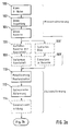
on réalise les structures sur la feuille de substrat selon les étapes suivantes :a) mise en place d'un outil de moulage sur la feuille,b) chauffage de la feuille,c) impression de l'outil de moulage dans la feuille,d) refroidissement de la feuille. - Procédé selon la revendication 4,
caractérisé en ce qu'
on précomprime la feuille de substrat en surface (116) avant d'imprimer l'outil de moulage. - Procédé selon la revendication 5,
caractérisé en ce qu'
on met le substrat (10) en pression pendant le frittage à l'aide d'un outil de pressage (23). - Procédé selon la revendication 9,
caractérisé en ce qu'
on applique un agent séparateur (17) entre l'outil de pressage (23) et le substrat (10). - Procédé selon la revendication 9,
caractérisé en ce que
l'outil de pressage (23) est une matière poreuse. - Procédé selon la revendication 9,
caractérisé en ce que
l'outil de pressage (23) est l'outil de moulage utilisé pour fabriquer les structures (11, 12, 13) dans le substrat (10). - Procédé selon la revendication 1,
caractérisé en ce qu'
on applique une pâte de verre lisse par frittage (126) sur le substrat (10) avant de le matricer. - Procédé selon la revendication 1,
caractérisé en ce qu'
on effectue tout d'abord une première étape de matriçage (124) avec une pression de matriçage réduite sur la micro-structure obtenue puis, on applique une matière lisse par frittage (126) puis on effectue une seconde étape de matriçage (128) pour réaliser la structure définitive. - Procédé selon la revendication 1,
caractérisé en ce qu'
on effectue un préséchage de la structure après application de la matière lisse par frittage. - Procédé selon la revendication 1,
caractérisé en ce que
sur le substrat structuré (10), on applique au cours d'une même étape de masquage (136), les chemins conducteurs (26) et des surfaces de contact (29) et on métallise la structure de déviation de la lumière (15). - Procédé selon la revendication 1,
caractérisé en ce que
la structure de déviation de la lumière (15) est en forme de miroir et la surface prévue à cet effet est tout d'abord lissée puis métallisée. - Procédé selon la revendication 1,
caractérisé en ce que
la structure de renvoi de la lumière (15) est en forme de miroir et la surface prévue pour cela reçoit tout d'abord une métallisation de base puis on renforce par une application galvanique améliorant la planéité ou renforçant la brillance. - Procédé selon la revendication 1,
caractérisé en ce que
la zone (12) de la structure servant à guider la fibre optique, à l'endroit où se trouve l'orifice de sortie (27) d'une fibre optique (20) placée dans la structure de guidage (11, 12, 13) est remplie d'une matière dont l'indice de réfraction est supérieur à 1. - Dispositif pour convertir des signaux optiques en signaux électriques comprenant un substrat dont la face supérieure comporte des structures pour guider une fibre optique et des moyens pour dévier la lumière transmise par la fibre optique sur un convertisseur placé sur le substrat pour convertir les signaux optiques en signaux électriques,
caractérisé en ce que
le substrat (10) est formé d'une matière de base céramique isolante électrique et le moyen de déviation de la lumière (15) est également formé sur la surface du substrat (10). - Dispositif selon la revendication 20,
caractérisé en ce que
la face supérieure (19) du substrat (10) comporte des chemins conducteurs (26, 26') pour transmettre les signaux électriques du convertisseur (22). - Dispositif selon la revendication 20,
caractérisé en ce que
les moyens pour dévier la lumière transmise par la fibre optique sont constitués par un miroir (15) à contour librement prédétermine. - Dispositif selon la revendication 20,
caractérisé en ce qu'
entre l'orifice de sortie de la fibre optique (27) et l'entrée (28) du convertisseur (22) on place une matière ayant un indice de réfraction supérieur à celui de l'air. - Dispositif selon la revendication 20,
caractérisé en ce qu'
à la place de la diode de réception, on utilise une diode laser à émission de surface dont la lumière est injectée dans la fibre optique par l'intermédiaire de l'élément déviateur.
Applications Claiming Priority (5)
| Application Number | Priority Date | Filing Date | Title |
|---|---|---|---|
| DE19501285A DE19501285C1 (de) | 1995-01-18 | 1995-01-18 | Anordnung zur Umsetzung von optischen in elektrische Signale und Verfahren zur Herstellung |
| DE19501285 | 1995-01-18 | ||
| DE19547941A DE19547941A1 (de) | 1995-01-18 | 1995-12-21 | Anordnung zur Umsetzung von optischen in elektrische Signale und Verfahren zur Herstellung |
| DE19547941 | 1995-12-21 | ||
| PCT/DE1996/000026 WO1996022177A1 (fr) | 1995-01-18 | 1996-01-10 | Systeme permettant de convertir des signaux optiques en signaux electriques et procede de production |
Publications (2)
| Publication Number | Publication Date |
|---|---|
| EP0804323A1 EP0804323A1 (fr) | 1997-11-05 |
| EP0804323B1 true EP0804323B1 (fr) | 1998-11-04 |
Family
ID=26011677
Family Applications (1)
| Application Number | Title | Priority Date | Filing Date |
|---|---|---|---|
| EP96900267A Expired - Lifetime EP0804323B1 (fr) | 1995-01-18 | 1996-01-10 | Systeme permettant de convertir des signaux optiques en signaux electriques et procede de production |
Country Status (3)
| Country | Link |
|---|---|
| US (1) | US5987202A (fr) |
| EP (1) | EP0804323B1 (fr) |
| WO (1) | WO1996022177A1 (fr) |
Families Citing this family (65)
| Publication number | Priority date | Publication date | Assignee | Title |
|---|---|---|---|---|
| JP3677348B2 (ja) * | 1996-05-24 | 2005-07-27 | 株式会社リコー | 光伝送モジュール |
| JP2907203B1 (ja) * | 1998-02-20 | 1999-06-21 | 住友電気工業株式会社 | 光モジュール |
| US6115521A (en) * | 1998-05-07 | 2000-09-05 | Trw Inc. | Fiber/waveguide-mirror-lens alignment device |
| EP0987769B1 (fr) * | 1998-09-18 | 2003-05-02 | Sumitomo Electric Industries, Ltd. | Module photodiode |
| DE19861162A1 (de) | 1998-11-06 | 2000-06-29 | Harting Elektrooptische Bauteile Gmbh & Co Kg | Verfahren zur Herstellung einer Leiterplatte sowie Leiterplatte |
| TW460717B (en) * | 1999-03-30 | 2001-10-21 | Toppan Printing Co Ltd | Optical wiring layer, optoelectric wiring substrate mounted substrate, and methods for manufacturing the same |
| JP2001174671A (ja) | 1999-12-16 | 2001-06-29 | Japan Aviation Electronics Industry Ltd | 光素子モジュール |
| DE10001679C2 (de) * | 2000-01-12 | 2001-11-29 | Infineon Technologies Ag | Optische Kopplungsanordnung |
| DE20013088U1 (de) * | 2000-07-28 | 2000-11-16 | Harting Elektrooptische Bauteile Gmbh & Co Kg | Optischer Transceiver |
| DE10043996A1 (de) * | 2000-09-05 | 2002-03-14 | Cube Optics Ag | Koppelvorrichtung und Verfahren zur Herstellung hierfür |
| DE10043985A1 (de) * | 2000-09-05 | 2002-03-14 | Cube Optics Ag | Optischer Modifizierer und Verfahren zur Herstellung hierfür |
| TW449797B (en) * | 2000-09-22 | 2001-08-11 | Ind Tech Res Inst | Integrated surface-emitting type electro-optical module and the fabrication method thereof |
| US6799902B2 (en) | 2000-12-26 | 2004-10-05 | Emcore Corporation | Optoelectronic mounting structure |
| DE10065624C2 (de) * | 2000-12-29 | 2002-11-14 | Hans Kragl | Kopplungsanordnung zum optischen Koppeln eines Lichtwellenleiters mit einem elektro-optischen oder opto-elektrischen Halbleiterwandler |
| GB2372108A (en) * | 2001-02-10 | 2002-08-14 | Bookham Technology Plc | Alignment of optical component using V-grooves in an optical chip |
| US6786651B2 (en) * | 2001-03-22 | 2004-09-07 | Primarion, Inc. | Optical interconnect structure, system and transceiver including the structure, and method of forming the same |
| WO2002077691A2 (fr) * | 2001-03-22 | 2002-10-03 | Primarion, Inc. | Structure d'interconnexion optique, systeme et emetteur-recepteur renfermant cette structure, et procede de fabrication associe |
| US20020195417A1 (en) * | 2001-04-20 | 2002-12-26 | Steinberg Dan A. | Wet and dry etching process on <110> silicon and resulting structures |
| US6704488B2 (en) * | 2001-10-01 | 2004-03-09 | Guy P. Lavallee | Optical, optoelectronic and electronic packaging platform, module using the platform, and methods for producing the platform and the module |
| US6934430B2 (en) * | 2002-02-04 | 2005-08-23 | Telephus Inc. | Optical module used in high frequency band optical communication system |
| US6688780B2 (en) | 2002-02-07 | 2004-02-10 | Amphenol Corporation | Cantilevered shutter for optical adapter |
| JP3833180B2 (ja) * | 2002-02-08 | 2006-10-11 | キヤノン株式会社 | 二次元光導波路の製造方法 |
| FR2836236B1 (fr) * | 2002-02-21 | 2004-09-17 | Framatome Connectors Int | Dispositif de couplage optoelectronique perfectionne |
| WO2003077001A1 (fr) * | 2002-03-14 | 2003-09-18 | The Hong Kong Applied Science Technology Research Instituted Co., Ltd. | Plate-forme integree pour alignement optique passif d'un dispositif a semi-conducteur avec fibre optique |
| KR20050007459A (ko) * | 2002-04-16 | 2005-01-18 | 엑스룸 포토닉스 리미티드 | 통합 커넥터를 구비한 전자 광학 회로 및 그 제조 방법 |
| US20040021214A1 (en) * | 2002-04-16 | 2004-02-05 | Avner Badehi | Electro-optic integrated circuits with connectors and methods for the production thereof |
| US7180929B2 (en) * | 2002-04-18 | 2007-02-20 | Intel Corporation | Wafer-level test structure for edge-emitting semiconductor lasers |
| GB2387714A (en) * | 2002-04-19 | 2003-10-22 | Denselight Semiconductors Pte | Mount for a semiconductor device |
| US6657272B2 (en) * | 2002-04-19 | 2003-12-02 | Triquint Technology Holding Co. | Off-axis silicon substrate for optimized optical coupling |
| US6850674B2 (en) * | 2002-05-09 | 2005-02-01 | Sumitomo Electric Industries, Ltd. | Optical device |
| JP2004088046A (ja) * | 2002-06-25 | 2004-03-18 | Sumitomo Electric Ind Ltd | 光受信器及びその製造方法 |
| US7150569B2 (en) * | 2003-02-24 | 2006-12-19 | Nor Spark Plug Co., Ltd. | Optical device mounted substrate assembly |
| US7343058B2 (en) * | 2003-04-22 | 2008-03-11 | Intel Corporation | Efficient light coupler from off-chip to on-chip waveguides |
| EP1479648A3 (fr) * | 2003-05-23 | 2005-10-19 | Rohm and Haas Electronic Materials, L.L.C. | Procédé de gravure des materiaux cristallins et dispositifs fabriqués avec ce procédé. |
| US6898347B2 (en) * | 2003-05-30 | 2005-05-24 | Intel Corporation | Monitoring power in optical networks |
| AU2003272062A1 (en) * | 2003-10-15 | 2005-04-27 | Xloom Photonics Ltd. | Electro-optical circuitry having integrated connector and methods for the production thereof |
| EP1548473B1 (fr) * | 2003-12-24 | 2008-06-11 | STMicroelectronics S.r.l. | Un module optique avec un dispositif optoélectronique et un dispositif de couplage optique réfléchissante |
| US7369718B2 (en) * | 2004-01-23 | 2008-05-06 | Intel Corporation | Package substrate pattern to accommodate optical waveguide |
| US7306378B2 (en) * | 2004-05-06 | 2007-12-11 | Intel Corporation | Method and apparatus providing an electrical-optical coupler |
| US7782921B2 (en) * | 2005-03-28 | 2010-08-24 | Intel Corporation | Integrated optical detector in semiconductor reflector |
| EP1715368B1 (fr) * | 2005-04-18 | 2008-04-09 | Varioprint AG | Procédé de fabrication d'un dispositif de couplage optique |
| KR100749528B1 (ko) * | 2005-09-30 | 2007-08-16 | 주식회사 두산 | 광 접속 모듈 및 그 제조 방법 |
| US7450621B1 (en) * | 2007-06-26 | 2008-11-11 | Avago Technologies Fiber Ip (Singapore) Pte. Ltd. | Integrated laser-diffractive lens device |
| US20090093137A1 (en) * | 2007-10-08 | 2009-04-09 | Xloom Communications, (Israel) Ltd. | Optical communications module |
| US8173045B2 (en) | 2008-05-28 | 2012-05-08 | University Of Washington | Diels-Alder crosslinkable dendritic nonlinear optic chromophores and polymer composites |
| US7703993B1 (en) * | 2008-12-17 | 2010-04-27 | National Semiconductor Corporation | Wafer level optoelectronic package with fiber side insertion |
| US9151918B2 (en) * | 2010-08-26 | 2015-10-06 | Vi Systems Gmbh | Opto-electronic assembly for parallel high speed transmission |
| EP2434321A1 (fr) | 2010-09-27 | 2012-03-28 | U2t Photonics Ag | Module optique |
| US8582618B2 (en) | 2011-01-18 | 2013-11-12 | Avago Technologies General Ip (Singapore) Pte. Ltd. | Surface-emitting semiconductor laser device in which an edge-emitting laser is integrated with a diffractive or refractive lens on the semiconductor laser device |
| US8818144B2 (en) | 2011-01-25 | 2014-08-26 | Tyco Electronics Corporation | Process for preparing an optical interposer for waveguides |
| AT12749U1 (de) * | 2011-04-01 | 2012-10-15 | Austria Tech & System Tech | Leiterplattenelement mit wenigstens einer led |
| US8315287B1 (en) | 2011-05-03 | 2012-11-20 | Avago Technologies Fiber Ip (Singapore) Pte. Ltd | Surface-emitting semiconductor laser device in which an edge-emitting laser is integrated with a diffractive lens, and a method for making the device |
| US9052460B2 (en) * | 2011-12-27 | 2015-06-09 | Neophotonics Corporation | Integrated circuit coupling system with waveguide circuitry and method of manufacture thereof |
| US9323010B2 (en) | 2012-01-10 | 2016-04-26 | Invensas Corporation | Structures formed using monocrystalline silicon and/or other materials for optical and other applications |
| US8757897B2 (en) * | 2012-01-10 | 2014-06-24 | Invensas Corporation | Optical interposer |
| US9054024B2 (en) * | 2012-02-13 | 2015-06-09 | Futurewei Technologies, Inc. | Apparatus and method for optical communications |
| US10180547B2 (en) * | 2012-02-23 | 2019-01-15 | Taiwan Semiconductor Manufacturing Company, Ltd. | Optical bench on substrate |
| US9618712B2 (en) | 2012-02-23 | 2017-04-11 | Taiwan Semiconductor Manufacturing Company, Ltd. | Optical bench on substrate and method of making the same |
| US9323014B2 (en) * | 2012-05-28 | 2016-04-26 | Mellanox Technologies Ltd. | High-speed optical module with flexible printed circuit board |
| US20130330033A1 (en) * | 2012-06-12 | 2013-12-12 | Futurewei Technologies, Inc. | Tsv substrate with mirror and its application in high-speed optoelectronic packaging |
| US20150331212A1 (en) * | 2013-01-31 | 2015-11-19 | Ccs Technology, Inc. | Method for forming optoelectronic modules connectable to optical fibers and optoelectronic module connectable to at least one optical fiber |
| JP6286853B2 (ja) * | 2013-04-04 | 2018-03-07 | 富士通株式会社 | 電子装置とその製造方法、及び電子機器 |
| US10151865B2 (en) * | 2014-05-02 | 2018-12-11 | Futurewei Technologies, Inc. | Compact external grating PBS/PBC coupler |
| US20170119250A1 (en) * | 2015-11-04 | 2017-05-04 | The Charles Stark Draper Laboratory, Inc. | Portable hardware fixture for fundoscopy |
| RU2670719C9 (ru) * | 2018-02-05 | 2018-11-29 | Российская Федерация, от имени которой выступает ФОНД ПЕРСПЕКТИВНЫХ ИССЛЕДОВАНИЙ | Оптоволоконный фотоэлектрический свч модуль |
Family Cites Families (14)
| Publication number | Priority date | Publication date | Assignee | Title |
|---|---|---|---|---|
| US4169001A (en) * | 1976-10-18 | 1979-09-25 | International Business Machines Corporation | Method of making multilayer module having optical channels therein |
| US4445274A (en) * | 1977-12-23 | 1984-05-01 | Ngk Insulators, Ltd. | Method of manufacturing a ceramic structural body |
| US4546065A (en) * | 1983-08-08 | 1985-10-08 | International Business Machines Corporation | Process for forming a pattern of metallurgy on the top of a ceramic substrate |
| GB2162335B (en) * | 1984-07-25 | 1988-07-13 | Adc Telecommunications Inc | Fibre optic coupler |
| DE3543558C2 (de) * | 1985-12-10 | 1996-09-19 | Licentia Gmbh | Opto-elektrische Koppelanordnung |
| US4897711A (en) * | 1988-03-03 | 1990-01-30 | American Telephone And Telegraph Company | Subassembly for optoelectronic devices |
| DE4106721A1 (de) * | 1991-03-02 | 1992-09-10 | Ant Nachrichtentech | Anordnung zur ankopplung von lichtwellenleiterenden an empfangselemente |
| DE4212208A1 (de) * | 1992-04-10 | 1993-10-14 | Bosch Gmbh Robert | Verfahren zur Herstellung optischer Polymerbauelemente mit integrierter Faser-Chip-Kopplung in Abformtechnik |
| DE4300652C1 (de) * | 1993-01-13 | 1994-03-31 | Bosch Gmbh Robert | Verfahren zur Herstellung einer hybrid integrierten optischen Schaltung und Vorrichtung zur Emission von Lichtwellen |
| JP3484543B2 (ja) * | 1993-03-24 | 2004-01-06 | 富士通株式会社 | 光結合部材の製造方法及び光装置 |
| DE4317953A1 (de) * | 1993-05-28 | 1994-12-01 | Siemens Ag | Verfahren zur Herstellung von Führungselementen für Lichtwellenleiter |
| CA2130738A1 (fr) * | 1993-11-01 | 1995-05-02 | Keith Wayne Goossen | Methode et dispositif de fabrication de miroirs a inclinaison quelconque dans les substrats pour les systemes optiques hybrides |
| DE69431512T2 (de) * | 1993-12-27 | 2003-06-18 | Nec Corp | Lichtempfängerstruktur für optische Vorrichtungen vom Wellenleitertyp |
| JP3828179B2 (ja) * | 1995-05-12 | 2006-10-04 | 富士通株式会社 | 半導体光検出装置およびその製造方法 |
-
1996
- 1996-01-10 EP EP96900267A patent/EP0804323B1/fr not_active Expired - Lifetime
- 1996-01-10 US US08/875,263 patent/US5987202A/en not_active Expired - Fee Related
- 1996-01-10 WO PCT/DE1996/000026 patent/WO1996022177A1/fr active IP Right Grant
Also Published As
| Publication number | Publication date |
|---|---|
| WO1996022177A1 (fr) | 1996-07-25 |
| US5987202A (en) | 1999-11-16 |
| EP0804323A1 (fr) | 1997-11-05 |
Similar Documents
| Publication | Publication Date | Title |
|---|---|---|
| EP0804323B1 (fr) | Systeme permettant de convertir des signaux optiques en signaux electriques et procede de production | |
| EP0614539B1 (fr) | Procede de fabrication d'un couvercle pour un circuit optique integre | |
| EP0635139B1 (fr) | Procede pour la fabrication de composants optiques en polymere avec couplage integre puce/fibre par moulage | |
| EP0630486B1 (fr) | Procede de fabrication d'un circuit optique integre de maniere hybride et dispositif permettant d'emettre des ondes lumineuses | |
| DE60301553T2 (de) | Optischer schaltkreis mit optischen planaren hohlkern-lichtwellenleitern | |
| EP0647328B1 (fr) | Element polymere optique pour coupler des cellules photo-electriques a des circuits optiques integres | |
| DE19619353A1 (de) | Verfahren zur Herstellung eines integriert optischen Wellenleiterbauteiles sowie Anordnung | |
| WO2003019617A2 (fr) | Procede de production de composants electroniques | |
| DE10023736A1 (de) | Leiterplatte sowie Verfahren zur Herstellung einer Leiterplatte | |
| DE112006000228T5 (de) | Optokoppler | |
| DE19623153B4 (de) | Optokoppler und Verfahren zur Herstellung desselben | |
| DE19501285C1 (de) | Anordnung zur Umsetzung von optischen in elektrische Signale und Verfahren zur Herstellung | |
| DE3939112C2 (fr) | ||
| EP0883825B1 (fr) | Procede de production de composants optiques avec guides d'ondes optiques accouples, et composants optiques produits selon ce procede | |
| DE4240950C1 (de) | Verfahren zum Herstellen eines Deckels für eine integriert optische Schaltung und Deckel für eine integriert optische Schaltung | |
| EP0731365B1 (fr) | Méthode de fabrication d'un dispositif électro-optique | |
| DE19616015C1 (de) | Anordnung zur Ankopplung optischer Sende- oder Empfangselemente an einen Lichtwellenleiter | |
| EP1671167B1 (fr) | Procede de realisation de cartes de circuits imprimes electro-optiques comprenant des guides d'onde polysiloxane, et leur utilisation | |
| DE10200853B4 (de) | Optische Lage mit optischen Leitern, Leiterplatte, Herstellungsverfahren für optische Lage mit optischen Leitern und Herstellungsverfahren für Leiterplatte | |
| DE10132794A1 (de) | Kopplung an in Leiterplatten eingebettete Lichtleiter | |
| DE19945470B4 (de) | Verfahren zum Herstellen einer mikrofunktionalen Verbundvorrichtung | |
| EP1005663A1 (fr) | Procede de production d'un composant optique integre a la puce a guides d'ondes avec connecteur enfichable | |
| DE4002098C2 (fr) | ||
| DE10222960A1 (de) | Verfahren zur Herstellung von elektronischen Bauelementen | |
| WO1998053349A1 (fr) | Procede de fabrication d'elements de commutation thermooptiques |
Legal Events
| Date | Code | Title | Description |
|---|---|---|---|
| PUAI | Public reference made under article 153(3) epc to a published international application that has entered the european phase |
Free format text: ORIGINAL CODE: 0009012 |
|
| 17P | Request for examination filed |
Effective date: 19970818 |
|
| AK | Designated contracting states |
Kind code of ref document: A1 Designated state(s): CH DE FR GB IT LI SE |
|
| GRAG | Despatch of communication of intention to grant |
Free format text: ORIGINAL CODE: EPIDOS AGRA |
|
| 17Q | First examination report despatched |
Effective date: 19980116 |
|
| GRAG | Despatch of communication of intention to grant |
Free format text: ORIGINAL CODE: EPIDOS AGRA |
|
| GRAH | Despatch of communication of intention to grant a patent |
Free format text: ORIGINAL CODE: EPIDOS IGRA |
|
| GRAH | Despatch of communication of intention to grant a patent |
Free format text: ORIGINAL CODE: EPIDOS IGRA |
|
| GRAA | (expected) grant |
Free format text: ORIGINAL CODE: 0009210 |
|
| AK | Designated contracting states |
Kind code of ref document: B1 Designated state(s): CH DE FR GB IT LI SE |
|
| REG | Reference to a national code |
Ref country code: CH Ref legal event code: NV Representative=s name: SCINTILLA AG, DIREKTION Ref country code: CH Ref legal event code: EP |
|
| REF | Corresponds to: |
Ref document number: 59600776 Country of ref document: DE Date of ref document: 19981210 |
|
| ITF | It: translation for a ep patent filed |
Owner name: STUDIO JAUMANN P. & C. S.N.C. |
|
| GBT | Gb: translation of ep patent filed (gb section 77(6)(a)/1977) |
Effective date: 19990112 |
|
| ET | Fr: translation filed | ||
| PLBE | No opposition filed within time limit |
Free format text: ORIGINAL CODE: 0009261 |
|
| STAA | Information on the status of an ep patent application or granted ep patent |
Free format text: STATUS: NO OPPOSITION FILED WITHIN TIME LIMIT |
|
| 26N | No opposition filed | ||
| REG | Reference to a national code |
Ref country code: GB Ref legal event code: IF02 |
|
| PGFP | Annual fee paid to national office [announced via postgrant information from national office to epo] |
Ref country code: GB Payment date: 20021218 Year of fee payment: 8 |
|
| PGFP | Annual fee paid to national office [announced via postgrant information from national office to epo] |
Ref country code: FR Payment date: 20030117 Year of fee payment: 8 |
|
| PGFP | Annual fee paid to national office [announced via postgrant information from national office to epo] |
Ref country code: SE Payment date: 20030123 Year of fee payment: 8 |
|
| PGFP | Annual fee paid to national office [announced via postgrant information from national office to epo] |
Ref country code: CH Payment date: 20030124 Year of fee payment: 8 |
|
| PGFP | Annual fee paid to national office [announced via postgrant information from national office to epo] |
Ref country code: DE Payment date: 20030225 Year of fee payment: 8 |
|
| PG25 | Lapsed in a contracting state [announced via postgrant information from national office to epo] |
Ref country code: GB Free format text: LAPSE BECAUSE OF NON-PAYMENT OF DUE FEES Effective date: 20040110 |
|
| PG25 | Lapsed in a contracting state [announced via postgrant information from national office to epo] |
Ref country code: SE Free format text: LAPSE BECAUSE OF NON-PAYMENT OF DUE FEES Effective date: 20040111 |
|
| PG25 | Lapsed in a contracting state [announced via postgrant information from national office to epo] |
Ref country code: LI Free format text: LAPSE BECAUSE OF NON-PAYMENT OF DUE FEES Effective date: 20040131 Ref country code: CH Free format text: LAPSE BECAUSE OF NON-PAYMENT OF DUE FEES Effective date: 20040131 |
|
| PG25 | Lapsed in a contracting state [announced via postgrant information from national office to epo] |
Ref country code: DE Free format text: LAPSE BECAUSE OF NON-PAYMENT OF DUE FEES Effective date: 20040803 |
|
| EUG | Se: european patent has lapsed | ||
| GBPC | Gb: european patent ceased through non-payment of renewal fee |
Effective date: 20040110 |
|
| REG | Reference to a national code |
Ref country code: CH Ref legal event code: PL |
|
| PG25 | Lapsed in a contracting state [announced via postgrant information from national office to epo] |
Ref country code: FR Free format text: LAPSE BECAUSE OF NON-PAYMENT OF DUE FEES Effective date: 20040930 |
|
| REG | Reference to a national code |
Ref country code: FR Ref legal event code: ST |
|
| PG25 | Lapsed in a contracting state [announced via postgrant information from national office to epo] |
Ref country code: IT Free format text: LAPSE BECAUSE OF NON-PAYMENT OF DUE FEES;WARNING: LAPSES OF ITALIAN PATENTS WITH EFFECTIVE DATE BEFORE 2007 MAY HAVE OCCURRED AT ANY TIME BEFORE 2007. THE CORRECT EFFECTIVE DATE MAY BE DIFFERENT FROM THE ONE RECORDED. Effective date: 20050110 |