EP0804040A2 - Appareil et procédé pour engendrer des fichiers d'images immobiles numériques à partir d'images animées numériques - Google Patents
Appareil et procédé pour engendrer des fichiers d'images immobiles numériques à partir d'images animées numériques Download PDFInfo
- Publication number
- EP0804040A2 EP0804040A2 EP97302779A EP97302779A EP0804040A2 EP 0804040 A2 EP0804040 A2 EP 0804040A2 EP 97302779 A EP97302779 A EP 97302779A EP 97302779 A EP97302779 A EP 97302779A EP 0804040 A2 EP0804040 A2 EP 0804040A2
- Authority
- EP
- European Patent Office
- Prior art keywords
- data
- file
- image
- digital
- frame
- Prior art date
- Legal status (The legal status is an assumption and is not a legal conclusion. Google has not performed a legal analysis and makes no representation as to the accuracy of the status listed.)
- Withdrawn
Links
Images


Classifications
-
- H—ELECTRICITY
- H04—ELECTRIC COMMUNICATION TECHNIQUE
- H04N—PICTORIAL COMMUNICATION, e.g. TELEVISION
- H04N5/00—Details of television systems
- H04N5/76—Television signal recording
- H04N5/91—Television signal processing therefor
- H04N5/93—Regeneration of the television signal or of selected parts thereof
-
- H—ELECTRICITY
- H04—ELECTRIC COMMUNICATION TECHNIQUE
- H04L—TRANSMISSION OF DIGITAL INFORMATION, e.g. TELEGRAPHIC COMMUNICATION
- H04L12/00—Data switching networks
- H04L12/28—Data switching networks characterised by path configuration, e.g. LAN [Local Area Networks] or WAN [Wide Area Networks]
- H04L12/40—Bus networks
- H04L12/40052—High-speed IEEE 1394 serial bus
- H04L12/40117—Interconnection of audio or video/imaging devices
-
- G—PHYSICS
- G11—INFORMATION STORAGE
- G11B—INFORMATION STORAGE BASED ON RELATIVE MOVEMENT BETWEEN RECORD CARRIER AND TRANSDUCER
- G11B27/00—Editing; Indexing; Addressing; Timing or synchronising; Monitoring; Measuring tape travel
- G11B27/02—Editing, e.g. varying the order of information signals recorded on, or reproduced from, record carriers
- G11B27/031—Electronic editing of digitised analogue information signals, e.g. audio or video signals
- G11B27/034—Electronic editing of digitised analogue information signals, e.g. audio or video signals on discs
-
- G—PHYSICS
- G11—INFORMATION STORAGE
- G11B—INFORMATION STORAGE BASED ON RELATIVE MOVEMENT BETWEEN RECORD CARRIER AND TRANSDUCER
- G11B27/00—Editing; Indexing; Addressing; Timing or synchronising; Monitoring; Measuring tape travel
- G11B27/10—Indexing; Addressing; Timing or synchronising; Measuring tape travel
- G11B27/19—Indexing; Addressing; Timing or synchronising; Measuring tape travel by using information detectable on the record carrier
- G11B27/28—Indexing; Addressing; Timing or synchronising; Measuring tape travel by using information detectable on the record carrier by using information signals recorded by the same method as the main recording
- G11B27/30—Indexing; Addressing; Timing or synchronising; Measuring tape travel by using information detectable on the record carrier by using information signals recorded by the same method as the main recording on the same track as the main recording
- G11B27/3027—Indexing; Addressing; Timing or synchronising; Measuring tape travel by using information detectable on the record carrier by using information signals recorded by the same method as the main recording on the same track as the main recording used signal is digitally coded
- G11B27/3063—Subcodes
-
- H—ELECTRICITY
- H04—ELECTRIC COMMUNICATION TECHNIQUE
- H04N—PICTORIAL COMMUNICATION, e.g. TELEVISION
- H04N1/00—Scanning, transmission or reproduction of documents or the like, e.g. facsimile transmission; Details thereof
- H04N1/00127—Connection or combination of a still picture apparatus with another apparatus, e.g. for storage, processing or transmission of still picture signals or of information associated with a still picture
- H04N1/00281—Connection or combination of a still picture apparatus with another apparatus, e.g. for storage, processing or transmission of still picture signals or of information associated with a still picture with a telecommunication apparatus, e.g. a switched network of teleprinters for the distribution of text-based information, a selective call terminal
- H04N1/00283—Connection or combination of a still picture apparatus with another apparatus, e.g. for storage, processing or transmission of still picture signals or of information associated with a still picture with a telecommunication apparatus, e.g. a switched network of teleprinters for the distribution of text-based information, a selective call terminal with a television apparatus
- H04N1/00297—Connection or combination of a still picture apparatus with another apparatus, e.g. for storage, processing or transmission of still picture signals or of information associated with a still picture with a telecommunication apparatus, e.g. a switched network of teleprinters for the distribution of text-based information, a selective call terminal with a television apparatus with a television signal recorder, e.g. for recording facsimile images on a VCR
-
- H—ELECTRICITY
- H04—ELECTRIC COMMUNICATION TECHNIQUE
- H04N—PICTORIAL COMMUNICATION, e.g. TELEVISION
- H04N1/00—Scanning, transmission or reproduction of documents or the like, e.g. facsimile transmission; Details thereof
- H04N1/32—Circuits or arrangements for control or supervision between transmitter and receiver or between image input and image output device, e.g. between a still-image camera and its memory or between a still-image camera and a printer device
- H04N1/32358—Circuits or arrangements for control or supervision between transmitter and receiver or between image input and image output device, e.g. between a still-image camera and its memory or between a still-image camera and a printer device using picture signal storage, e.g. at transmitter
- H04N1/32491—Circuits or arrangements for control or supervision between transmitter and receiver or between image input and image output device, e.g. between a still-image camera and its memory or between a still-image camera and a printer device using picture signal storage, e.g. at transmitter alternate storage in and retrieval from two parallel memories, e.g. using ping-pong buffers
-
- H—ELECTRICITY
- H04—ELECTRIC COMMUNICATION TECHNIQUE
- H04N—PICTORIAL COMMUNICATION, e.g. TELEVISION
- H04N5/00—Details of television systems
- H04N5/76—Television signal recording
- H04N5/765—Interface circuits between an apparatus for recording and another apparatus
-
- H—ELECTRICITY
- H04—ELECTRIC COMMUNICATION TECHNIQUE
- H04N—PICTORIAL COMMUNICATION, e.g. TELEVISION
- H04N5/00—Details of television systems
- H04N5/76—Television signal recording
- H04N5/765—Interface circuits between an apparatus for recording and another apparatus
- H04N5/775—Interface circuits between an apparatus for recording and another apparatus between a recording apparatus and a television receiver
-
- H—ELECTRICITY
- H04—ELECTRIC COMMUNICATION TECHNIQUE
- H04N—PICTORIAL COMMUNICATION, e.g. TELEVISION
- H04N5/00—Details of television systems
- H04N5/76—Television signal recording
- H04N5/91—Television signal processing therefor
-
- G—PHYSICS
- G11—INFORMATION STORAGE
- G11B—INFORMATION STORAGE BASED ON RELATIVE MOVEMENT BETWEEN RECORD CARRIER AND TRANSDUCER
- G11B2220/00—Record carriers by type
- G11B2220/90—Tape-like record carriers
-
- H—ELECTRICITY
- H04—ELECTRIC COMMUNICATION TECHNIQUE
- H04N—PICTORIAL COMMUNICATION, e.g. TELEVISION
- H04N17/00—Diagnosis, testing or measuring for television systems or their details
- H04N17/06—Diagnosis, testing or measuring for television systems or their details for recorders
-
- H—ELECTRICITY
- H04—ELECTRIC COMMUNICATION TECHNIQUE
- H04N—PICTORIAL COMMUNICATION, e.g. TELEVISION
- H04N2201/00—Indexing scheme relating to scanning, transmission or reproduction of documents or the like, and to details thereof
- H04N2201/0008—Connection or combination of a still picture apparatus with another apparatus
- H04N2201/0065—Converting image data to a format usable by the connected apparatus or vice versa
- H04N2201/0067—Converting to still picture data
-
- H—ELECTRICITY
- H04—ELECTRIC COMMUNICATION TECHNIQUE
- H04N—PICTORIAL COMMUNICATION, e.g. TELEVISION
- H04N2201/00—Indexing scheme relating to scanning, transmission or reproduction of documents or the like, and to details thereof
- H04N2201/32—Circuits or arrangements for control or supervision between transmitter and receiver or between image input and image output device, e.g. between a still-image camera and its memory or between a still-image camera and a printer device
- H04N2201/3285—Circuits or arrangements for control or supervision between transmitter and receiver or between image input and image output device, e.g. between a still-image camera and its memory or between a still-image camera and a printer device using picture signal storage, e.g. at transmitter
- H04N2201/3288—Storage of two or more complete document pages or image frames
-
- H—ELECTRICITY
- H04—ELECTRIC COMMUNICATION TECHNIQUE
- H04N—PICTORIAL COMMUNICATION, e.g. TELEVISION
- H04N5/00—Details of television systems
- H04N5/44—Receiver circuitry for the reception of television signals according to analogue transmission standards
- H04N5/4448—Receiver circuitry for the reception of television signals according to analogue transmission standards for frame-grabbing
-
- H—ELECTRICITY
- H04—ELECTRIC COMMUNICATION TECHNIQUE
- H04N—PICTORIAL COMMUNICATION, e.g. TELEVISION
- H04N5/00—Details of television systems
- H04N5/76—Television signal recording
- H04N5/765—Interface circuits between an apparatus for recording and another apparatus
- H04N5/77—Interface circuits between an apparatus for recording and another apparatus between a recording apparatus and a television camera
- H04N5/772—Interface circuits between an apparatus for recording and another apparatus between a recording apparatus and a television camera the recording apparatus and the television camera being placed in the same enclosure
-
- H—ELECTRICITY
- H04—ELECTRIC COMMUNICATION TECHNIQUE
- H04N—PICTORIAL COMMUNICATION, e.g. TELEVISION
- H04N9/00—Details of colour television systems
- H04N9/79—Processing of colour television signals in connection with recording
- H04N9/80—Transformation of the television signal for recording, e.g. modulation, frequency changing; Inverse transformation for playback
- H04N9/804—Transformation of the television signal for recording, e.g. modulation, frequency changing; Inverse transformation for playback involving pulse code modulation of the colour picture signal components
- H04N9/8042—Transformation of the television signal for recording, e.g. modulation, frequency changing; Inverse transformation for playback involving pulse code modulation of the colour picture signal components involving data reduction
-
- H—ELECTRICITY
- H04—ELECTRIC COMMUNICATION TECHNIQUE
- H04N—PICTORIAL COMMUNICATION, e.g. TELEVISION
- H04N9/00—Details of colour television systems
- H04N9/79—Processing of colour television signals in connection with recording
- H04N9/80—Transformation of the television signal for recording, e.g. modulation, frequency changing; Inverse transformation for playback
- H04N9/804—Transformation of the television signal for recording, e.g. modulation, frequency changing; Inverse transformation for playback involving pulse code modulation of the colour picture signal components
- H04N9/806—Transformation of the television signal for recording, e.g. modulation, frequency changing; Inverse transformation for playback involving pulse code modulation of the colour picture signal components with processing of the sound signal
- H04N9/8063—Transformation of the television signal for recording, e.g. modulation, frequency changing; Inverse transformation for playback involving pulse code modulation of the colour picture signal components with processing of the sound signal using time division multiplex of the PCM audio and PCM video signals
-
- H—ELECTRICITY
- H04—ELECTRIC COMMUNICATION TECHNIQUE
- H04N—PICTORIAL COMMUNICATION, e.g. TELEVISION
- H04N9/00—Details of colour television systems
- H04N9/79—Processing of colour television signals in connection with recording
- H04N9/80—Transformation of the television signal for recording, e.g. modulation, frequency changing; Inverse transformation for playback
- H04N9/82—Transformation of the television signal for recording, e.g. modulation, frequency changing; Inverse transformation for playback the individual colour picture signal components being recorded simultaneously only
- H04N9/8205—Transformation of the television signal for recording, e.g. modulation, frequency changing; Inverse transformation for playback the individual colour picture signal components being recorded simultaneously only involving the multiplexing of an additional signal and the colour video signal
- H04N9/8227—Transformation of the television signal for recording, e.g. modulation, frequency changing; Inverse transformation for playback the individual colour picture signal components being recorded simultaneously only involving the multiplexing of an additional signal and the colour video signal the additional signal being at least another television signal
Definitions
- the present invention is related to image processing and, in particular, to an apparatus and method for recording digital still images on a data storage medium (e.g., a floppy disk) based on moving images reproduced from a digital VTR (Video Tape Recorder), for example.
- a data storage medium e.g., a floppy disk
- VTR Video Tape Recorder
- a personal computer may, for example, be used for displaying image data, captured from an outside source (a video camera), on a monitor device connected to the computer. Various processing operations may then be performed on the captured image data utilizing image processing software, for example.
- VTRs including digital camcorders
- the digital VTRs are capable of obtaining higher quality pictures than analog VTRs, that is VTRs for recording and reproducing analog image signals.
- VTRs for recording and reproducing analog image signals.
- the digital VTR records/reproduces the digital image using a special recording/reproducing format that is not compatible with display/manipulation of the digital images (in units of picture frames, for example) by the computer.
- the image represented by a digital signal is typically converted to an analog signal (represented as picture frames) to be captured by the computer prior to its processing operations. It is apparent that these conversions between analog and digital domains negatively affect picture quality.
- a still image represented by frame data
- a data file corresponding to the still image is then generated.
- the data file includes the extracted frame data and file management data corresponding to the extracted frame data.
- the file management data includes at least one of the following: file identification information for identifying the data file; file version information for indicating the data file version; detailed format information for indicating a data format of the digital moving image data; data attribute information for specifying preselected data attributes; file size information for indicating the entire data file length; data size information for indicating the length of the extracted frame data in the data file; and data offset information for indicating the length of the file management data.
- images represented by digital signals are recorded/reproduced according to a preselected video format, wherein these digital signals correspond to the digital moving image data.
- FIG. 1 is a block diagram showing an exemplary configuration of the image capturing system of the present invention.
- a microprocessor-controlled system includes a general purpose computer 2 for receiving and processing digital images and a monitor 9, connected to the computer 2, for displaying the processed digital images.
- the digital VTR 1 which includes a digital camcorder for recording images on a recording medium (a tape) as a moving image digital signal.
- the digital VTR 1 can also output image information reproduced from the tape or directly captured by the camera portion of the VTR 1.
- the output image information is a digital signal supplied to the computer 2 via a direct digital image signal output terminal 1a (hereinafter referred to as a "DV terminal").
- DV terminal direct digital image signal output terminal
- the computer 2 captures at least a still image from the image data supplied by the digital VTR 1, and creates a still image file for displaying the image on the monitor 9.
- the computer 2 is equipped with an image capturing board 3 which is configured to capture the image data supplied by the digital VTR 1.
- the image capturing board 3 is provided with a DV terminal 3a, such that the image data from the digital VTR 1 is supplied via this terminal.
- the digital moving image data can be directly transferred to the computer 2 via the DV terminal 3a.
- an IEEE 1394 digital serial bus may be adopted as the network standard for transferring data between the digital VTR 1 and the computer 2.
- FIG. 1 Further shown in FIG. 1 is a programmable controller 4 for controlling Various operations of the computer 2.
- An image capturing program 4a is stored in a data storage area of the controller 4: the program 4a instructions are executed by the controller 4, thereby causing the image capture operation to be carried out by the image capturing board 3.
- a Random Access Memory (RAM) 4b stores data in connection with the execution of instructions by the controller 4. It will be appreciated that the image capturing board 3 and the image capturing program 4a may be available in combination (as a set, for example).
- FIG. 1 also shows a recording/playback device 5 for controlling reading/writing operations for each of the image files to/from a recording medium 6.
- a recording/playback device 5 for controlling reading/writing operations for each of the image files to/from a recording medium 6.
- an internal disk drive is used as the recording/playback device 5; however, other driver devices may be used for recording/reproducing information on a hard disk, a floppy disk or other storage media.
- a display driver 7 converts the picture information from the image files to an RGB signal, for example.
- the monitor 9 then displays images based on the RGB signal supplied from the display driver 7.
- an input device 10 e.g., a keyboard, a mouse, etc.
- the computer 2 such that commands from the user-manipulated input device 10 are supplied to the controller 4 via a keyboard interface 8.
- An appropriate processing operation is then executed in accordance with the operational commands entered at the input device 10.
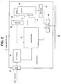
- FIG. 2 is a detailed block diagram of a representative configuration of the image capturing board 3.
- the image capturing board 3 includes the DV terminal 3a, an input interface 20, a board controller 21, data buffers 22, 24, a frame memory 23 and a data bus buffer 25.
- the digital image data (moving images from the VTR 1) is supplied to the input interface 20 via the DV terminal 3a.
- the digital image data is converted to a data transfer rate and data structure for use by the board controller 21 and by the data buffer 22.
- the board controller 21 determines the frame start position and image data identification (isochronous transmission or multicast transmission) with respect to the IEEE 1394 standard based on the image data synchronization and control information provided by an information signal S3 (NTSC/PAL).
- the information signal S3 (indicating whether the NTSC or PAL standard is used in the image data, for example) is also used for controlling writing/reading the image data to/from the frame memory 23.
- the frame memory 23 stores digital image data transmitted from the data buffer 22 in frames.
- the frame memory 23 has two storage areas, a bank A and a bank B, each capable of storing image data in units of frame. Further, the writing of frames to the banks A, B is carried out alternately. The reading of frames is also carried out alternately with respect to the banks A, B so as to become the opposite operation with respect to write cycles. For example, the reading operation of frame data stored in the bank B takes place while new frame data is written to the bank A. Then, during the next cycle, new frame data is written to the bank B at the same time when the data from the bank A is read. This reading/writing process, alternately repeated until instructed otherwise, is controlled by the board controller 21 supplying memory control signals S1 and S2 to the bank A and bank B, respectively.
- the image data format is defined based on at least the NTSC standard and the PAL standard.
- the information signal S3 indicating whether the image data is in the NTSC standard or in the PAL standard is supplied to the input interface 20 and the board controller 21.
- a signal capable of identifying both formats can be obtained by changing a jumper line connection for a preselected circuit part in one embodiment of the present invention.
- the present invention is by no means limited in this respect, and the format can be, for example, determined by carrying out identification based on information included in the image data. Alternatively, user-operated changes may be performed by the image capturing control program.
- the board controller 21 and the input interface 20 carry out the required data processing and reading/writing operations from/to the frame memory 23 in accordance with the respective NTSC and PAL standards based on the inputted information signal S3.
- Frame data retrieved from the frame memory 23 is transmitted to the data bus buffer 25 via the data buffer 24.
- Image data (in frames) is then transmitted to the controller 4 (FIG. 1) via the bus line 26 with which the image capturing board 3 is communicatively coupled.
- still image files are generated based on the transmitted image data.
- the user connects the computer 2 (having the image capturing board 3) and the digital VTR 1 via a cable, etc., between DV terminals 1a and 3a.
- the image capturing program 4a is then activated by operating a particular input key of the input device 10 so that the image capturing operation is initiated.
- the playback operation of the digital VTR 1 is supplied to the computer 2 as a digital signal via the DV terminals 1a and 3a
- FIG. 3 shows the display screen for the image capturing operation displayed on the monitor 9 while the image capturing program 4a is running.
- the image capturing program 4a when the playback operation of the digital VTR 1 is initiated as described above, the image capturing program 4a generates display image information for a candidate frame of the transmitted image data to be captured as a still image.
- the display image information is displayed in an image display window W1 in the upper right-hand corner of the display region as shown in FIG. 3. That is, the image currently being played back by the digital VTR 1 is displayed in the image display window W1 as a moving image.
- the image is designated as such by the user while viewing the image display window W1.
- a cursor (not shown in the figure) may be positioned on an image capturing key display K for image capturing use, and then a mouse button for selecting the desired image is clicked.
- the image capturing program 4a captures the frame image displayed in the image display window W1 for which the above operation had been carried out.
- the still image file is created, and the data for this file data is stored to the recording medium 6.
- a captured image display window W2 is provided so that the user can distinguish between various still image files. Namely, an image file icon I, used in selecting the still image files, is displayed according to the sequential (or random, if preferred) capturing operation of images, for example.
- image data based on the recording formats of the digital VTR 1 is captured as still image data by the computer 2.
- the format of the digital data outputted by the digital VTR 1 and the image capturing board 3 operation corresponding to this format is described with reference to FIGS. 4A-8.
- the image data recorded by the digital VTR 1 may be image/audio data compressed in accordance with Discrete Cosine Transform (DCT) operation.
- the image information data transmitted according to the IEEE 1394 standard via the DV terminal 1a may also be based on the recording format of the digital VTR 1.
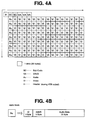
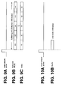
- FIG. 4A shows a typical data configuration of a single track data portion on the magnetic tape corresponding to the compressed image data played back at the digital VTR 1.
- the individual data units shown by the solid lines in FIG. 4A are referred to as blocks, wherein one block is 80 bytes.
- One track portion of the playback data has 149 blocks as indicated by the solid block lines.
- the leading block (header H) is shown by the dashed lines and is appended to the track data.
- a Sub Code (SC) block, a VAUX (VA) block, an Audio (Au) block and a Video (Vi) block are types of data blocks recorded on the tracks. Data such as time codes, etc., is recorded in the Sub Code block, and various management and information data relating to the image signal may be found in the VAUX block.
- FIG. 4B shows the Audio block configuration including an AAUX area (5 bytes) and an Audio Data area (72 bytes) following the leading ID area (3 bytes). Similar to the VAUX data, the AAUX data contains various management information relating to the audio signal.
- At least two types of formats such as the SD525, based on the NTSC standard, and the SD625 format, based on the PAL standard, are defined as the recording formats for the digital VTR 1.
- the SD525 format one frame contains 10 tracks, and in the SD625 format, one frame has 12 tracks recorded on the magnetic tape.
- a header block H based on the IEEE 1934 standard is added to the start of track data, as shown in FIG. 4A.
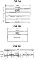
- FIG. 5A shows a representative packet data configuration. Transmission via the DV terminal is carried out in packets.
- the leading four bytes of the packet are as follows: a 1394 header shows whether the transmission is based on the IEEE 1394 standard; the second four-byte data portion is CRC (cyclic redundancy check) pertaining to the 1394 header; the third and fourth four-byte data portions are AV headers 1, 2 corresponding to data blocks.
- the final 125th four-byte portion is a CRC coding region for the data region.
- FIG. 5B shows the data structure for one block.
- one block is 80 bytes: a Digital Interface (DIF) ID0 area, a DIF ID1 area and a DIF ID2 area each includes one byte, while the remaining 77 bytes are video/audio data-storage area.
- DIF Digital Interface
- the type of data stored in the data area changes depending on the block type, as shown in FIG. 4A.
- FIG. 5C shows the configuration of the DIF ID0 area, DIF ID1 area and DIF ID2 area.
- the upper 3 bits denote the Data Type region indicating the block data type.
- the Data Type is defined as shown in FIG. 6A. If the three bits are 000, a header block is indicated. Further, 001 indicates a Sub Code block, 010 indicates a VAUX block, 011 indicates an Audio block and 100 indicates a Video block. Here, 101, 110 and 111 are reserved for future use.
- the five bits from the fifth upper bit to the LSB of the DIF ID0 area denote the Sequence No. region for indicating a sequence number for the transmission data blocks.
- the fourth upper bit is reserved.
- the upper four bite of the DIF ID1 area designate a Sub-Sequence No. region.
- the Sub-Sequence No. corresponds to the track number (Track No.) within one frame, as shown in FIG. 6B.
- the track number ranges between 0 and 9 to indicate which of the 10 tracks (one frame) the data belongs to.
- the track number ranges between 0 and 11 to show which of the 12 tracks (one frame) the data belongs to.
- the lower three bits are reserved, and the fifth upper bit is set to 0 in the DIF ID1 area.
- the eight bits of the DIF ID2 area designate the DIF Block No. region as shown in FIG. 6C.
- the DIF Block No. is 0 because there is only one header block.
- the current block is a Sub Code block
- the first Sub Code block of the two Sub Code blocks within one track is assigned a binary 0, while the following Sub Code block is assigned a binary 1 (as shown in FIG. 6C).
- the current block is a VAUX block, 0 to 2 are sequentially assigned within the single track.
- the current block is an Audio block, the values 0 to 8 (binary) are sequentially assigned within the track.
- the values 0 to 134 are sequentially assigned within the single track. Using this block number assignment, a block position of the same data type within a track can be determined based on the DIF Block No in the DIF ID2 area.
- the identification area A of the DIF ID0 and ID1 regions is extracted from the transmitted data, and the contents of this region are accessed.
- the identification area A is a region for the Data Type and Sub-Sequence No., as previously stated.
- header blocks are added to the beginning of each track, as shown in FIG. 4A.
- the end of the track data can then be identified for the transmitted data, if the header blocks are detected.
- Whether or not a block is a header block can be determined by referring to the contents of the Data Type to ascertain whether the Data Type is 000, as shown in FIG. 6A.
- 0 is assigned to the first track of the 10 (SD525 format) or 12 (SD625 format) tracks comprising one frame as the Sub-Sequence No., as shown in FIG. 6B. Header blocks of Sub-Sequence No. 0 indicate a frame start position.
- the frame start position is found.
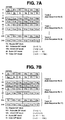
- FIGS. 7A and 7B show the configuration of data blocks that are transmitted in packets from the digital VTR 1, with FIG. 7A showing the SD525 format corresponding to the NTSC transmission standard.
- 6 blocks are included in one packet, but in FIG. 7A, 6 blocks of data are shown as one packet per each line. Namely, during the transmission by the digital VTR 1, this can be regarded as handling data for 6 blocks assembled into one.
- the numbers 0 to 249 assigned to each line in FIG. 7A show packet numbers all pertaining to a single frame.
- the numbers assigned to each data block correspond to the transmission order for each block type and correspond to the data arrangement order of the data structure previously described in connection with FIG. 4.
- 25 packets (packets 0 to 24) contain data corresponding to the first track of the first frame. Namely, 0 is added to the Sub-Sequence No. in the DIF ID1 of each block in these 25 packets, as shown in FIGS. 7A and 7B.
- the second track (Track 1) within the frame is then transmitted via 25 packets numbered 25 through 49.
- the configuration of the 150 blocks within these packets is the same as the arrangement of blocks for Track 0 defined by the packets 0 through 24. In contrast to the previous blocks 0-24, however, 1 is assigned as the Sub-Sequence No. of the DIF ID1 for each block 25-49.
- Transmission of data for one frame can then be completed by carrying out data transmission from packet 0-249 (that is, the final packet of the tenth track (Track 9)).
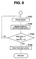
- the transmitted image data is captured, and the image data is extracted in frames by the image capturing board 3. It is, therefore, necessary to determine the frame start position based on the identification area A (Data Type and Sub-Sequence No.) of the DIF ID region, as shown in FIG. 5C.
- step F101 the receiving operation of the image data transmitted in packet units, is carried out.
- step F102 the contents of the fifth four-byte data portion (counted from the beginning of the packet, as shown in FIG. 5A) are ascertained.
- the header block positioned at the beginning of the track starts the data block region (the fifth four-byte data portion from the beginning of the packet) every 25 packets.
- the identification area A is located in the leading two bytes of each block. The header block identification area A is, therefore, always obtained if the fifth four-byte data portion, from the beginning of the packet, is accessed.
- step F103 it is determined in step F103 whether the Data Type and Track No. of the identification area A both have 0. When this is not the case, the operation returns to step F101, and the process is continued. If, however, in step F103, it is determined that the Data Type and Track No. both have 0, frame start position detection information is obtained in step F104. The board controller 21 can then properly control the writing operation to the frame memory 23 based on this detection result.
- FIGS. 9A-10B show the image data formats processed by the image capturing board 3. As shown in FIGS. 9B and 9C, transmission of the image data is carried out in six data units forming one packet. Namely, in the image capturing board 3, packets are partitioned into data units. The Sub Code, VAUX and Video blocks, as shown in FIGS. 9B and 9C, are processed as the buffering unit consisting of 5 blocks.
- the header blocks are only necessary at the time of data transmission from the digital VTR 1, based on the IEEE 1394 standard, and are therefore not needed by the image capturing board 3. That is, the board controller 21 controls the data writing operation in such a way that the 80 bytes of header block are not written to the frame memory 23. To do this, the header block data is separated from other block data groups.
- the Video enable pulse indicates the leading block within each buffering unit: the image data is written to the frame memory 23 (as five blocks (400 bytes) that form a buffering unit) at the falling edge of the Video enable pulse.
- a Sub Code block and VAUX block correspond to the group of blocks of the first row in FIG. 4A.
- the writing operation of the track data then starts from a buffering unit comprising two Sub Code blocks and three VAUX blocks.
- the Video blocks are subsequently transmitted as buffering units.
- Audio block is transmitted in one block units, as shown in FIGS. 10A and 10B.
- Each audio block is preceded by an Audio enable pulse showing the start position of the block that is written to the frame memory 23 on the falling edge of the Audio enable pulse.
- One frame portion of the image data is then obtained by writing ten tracks of data for Track 0 to 9 (or 12 tracks of data for Track 0 to 11).
- the frame data stored in the frame memory 23 is read at predetermined clock cycles by the board controller 21 and is supplied from the image capturing board 3 to the controller 4 via the bus line 26. Then, this frame data is converted to a still image file according to the description with reference to FIGS. 11A-12D.
- the still image file is generated under the control of the controller 4 executing the instructions of the image capturing program 4a.
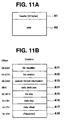
- FIG. 11A shows the data structure for an image file containing one still image (one frame).
- the image file begins with a header area A1 comprising 32 bytes.
- the header area A1 arranged in four-byte portions, stores various file management information (as described below with reference to FIG. 11B) for use in managing the image files recorded on the recording medium.
- a data area A2 is provided for the image data, where data is arranged in two-byte units.
- the data area A2 contains one frame of the image data. If the format is NTSC-compatible (SD525), 1490 data blocks from 10 tracks are arranged sequentially (Track 0 through Track 9). If the format is PAL-compatible (SD625), 1490 data blocks from 12 tracks are arranged sequentially (Track 0 through Track 11).
- the image data outputted by the digital VTR 1 via the DV terminal 1a undergoes compression processing using a predetermined format.
- the image file contains one frame of compression-processed image data. Consequently, the image file is small, and the recording capacity of the recording medium is efficiently utilized during the image file storage.
- FIG. 11B shows the data configuration of the header area A1.
- the definition of each region of the header area A1 is described with reference to FIGS. 12A-12D.
- the 32 byte header area A1 includes, from the top, a file identification area A11, a file version area A12, a detailed format information area A13, a data attribute area A14, a file size area A15, a data size area A16, a data offset area A17 and a Reserved area A18.
- the file identification area A11 is represented by four bytes of ASCII code for file identification, and, for example, in the system of the present embodiment is set to "DVF".
- the file version area A12 defines the file version using four bytes of ASCII code and is, for example, "1.00" in the case of version 1.00.
- the detailed format information area A13 indicates a format particular to various television formats using three bytes of ASCII code. The definition for this detailed format information is shown in FIG. 12A. Two exemplary codes used in this embodiment are "SD5" for the SD525 format, and "SD6" for the SD625 format. In this embodiment, only the SD525 and SD625 formats have been described.
- the data attribute area A14 stores prescribed information showing the attributes relating to the image file, using one data byte. This area is utilized to store 0 or 1 according to the attributes set up for each of the eight bits shown in FIG. 12B for which the required attribute data is defined.
- the file size area A15 defines the data size of the entire image file, using four bytes of the binary code. The file sizes of SD525 and SD625 are shown in FIG.
- the image file size is set to 119232 bytes based on the SD525 format, with the 119232 bytes therefore being shown as "0001D1C0" in hexadecimal notation.
- the data size of the image file has a fixed length of 143072 bytes based on the SD625 format, which is shown as "00022EE0" in the hexadecimal notation.
- the data offset area A17 defines the offset to the data area A2 from the header area A1 (that is, the end position of the header area from the start of the image file) using four bytes (in binary). In this case, 32 bytes of the header area A1 is "00000020" in the hexadecimal notation. If, for example, it becomes necessary to increase the number of items (areas) in the header area A1 requiring more than 32 bytes, the data offset area A17 may be changed accordingly, thereby providing compatibility with future format changes, etc.
- image files based on the captured image data are generated by the controller 4, as described with reference to FIGS. 11A-12D. Namely, with respect to the frame data supplied to the controller 4 from the image capturing board 3, the definitional contents of each area (A11-A18) corresponding to the supplied image type (NTSC standard, PAL standard, etc.) are provided to the header area A1 that is added to the file, and the image file of the structure shown in FIG. 11A is thus generated. An appropriate file name is then given to the image file that is recorded (saved) to the recording medium 6.
- FIG. 13 is a flowchart showing the processing operation in accordance with the image capturing program 4a for generating and saving the image file.
- the program instructions executed by the controller 4 direct the processing operation to wait for an activation of the key (as described above with reference to FIG. 3) in step F201. During this time, display control for displaying the display screen P (as described above with reference to FIG. 3) is carried out based on a processing operation of another program.
- step F201 If, in step F201, the key for the image capturing operation is activated, it is determined, in step F202, whether the frame data for the selected image is appropriate/valid.
- the frame data is discarded in step F203 without capturing the frame data into memory. In this case, it is indicated on the display screen that the image capturing operation was not performed. Alternatively, high correlation between frames may be indicated.
- the appropriateness/inappropriateness of a predetermined number of immediately following frames may be monitored.
- step F204 determines the supplied image data format.
- the two formats SD525 corresponding to the NTSC standard and SD625 corresponding to the PAL standard
- step F204 either the SD525 format or the SD625 format is selected.
- the format determination can be carried out by utilizing the information signal S3 for identifying the NTSC/PAL standard obtained at the image capturing board 3, as previously described.
- step F205 a header (as shown in FIGS. 1 and 12) for the contents corresponding to the SD525 format is generated.
- An appropriate file name is then given to the header, and under the control of the controller 4, the recording/playback device 5 writes the header information and file name to the recording medium 6.
- the file name in this embodiment may be, for example, "*****. DVF". Namely, ".DVF" is added as an extension to an arbitrary file name.
- the frame data is read from the frame memory 23 in track order, where one frame of data contains 10 tracks of data.
- step F206 data contained in 10 tracks is retrieved from the frame memory 23 and is sequentially written to the recording medium 6, following the header written to the recording medium 6 previously in step F205.
- the data writing operation for track 9 is finished, i.e. when the frame is completed, an image file of the configuration shown in FIG. 11A is generated and saved on the recording medium 6.
- step F204 a header for the contents corresponding to the SD625 format is generated in step F207.
- An appropriate file name is then given to the header, and the recording/playback device 5 writes the header information and file name to the recording medium 6.
- step F206 data contained in 12 tracks is retrieved from the frame memory 23 and is sequentially written to the recording medium 6, following the header.
- an image file is generated and saved on the recording medium 6.
- the image capturing program 4a as executed by the controller 4, also performs display functions for displaying the generated image files.
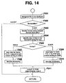
- the processing operation shown in FIG. 14 can therefore be carried out in accordance with the image capturing program 4a.
- the image capturing program 4a operation is initiated when the user activates the input device 10 of the computer 2 and selects a moving image in order to designate an image file for display as a still image on the monitor 9.
- the designated image file is received in step F301, and its header is retrieved from the recording medium 6.
- the file identification area A11 (FIG. 11B) is accessed, and the file type is identified.
- the processing is terminated, and the user is notified, for example, via monitor display, that the designated file data was not processed by the image capturing program.
- step F302 when the controller 4 determines in step F302 that the file identification is DVF, the detailed format information from area A13 (FIG. 11B) is retrieved in step F303 for identifying the video transmission format (SD525, SD625, etc.).
- step F304 the information from the file size area A15 is obtained, and the data size (i.e., the size of the data area A2 with the header area A1 removed from the image file) is determined.
- step F305 the controller 4 determines whether the format identified in step F303 is SD525 or SD625. If the format is SD525, in step F307, data is read out (in the order of Track 0 to Track 9) from the recording medium 6 and written to the RAM 4b based on the SD525 format. That is, the data is accumulated for one still image in the RAM 4b, as obtained from the data area A2 of the image file.
- the data in the image file is frame compressed in accordance with the appropriate recording format of the digital VTR 1.
- step F308 in addition to performing, for example, inverse DCT transformation, etc., on the image data stored in the RAM 4b, the execution of the image capturing program 4a by the controller 4 causes the decoding operation of the image data (expansion processing) to take place. Then, in step F311, the display driver 7 is controlled (based on the data for the still image for which the decoding operation has been performed) to output an RGB signal representing one captured image. Namely, the data in the image file designated by the user is accessed and displayed on the monitor 9.
- step F305 if the format is determined to be SD625, the image data is read from the recording medium 6 based on the SD625 format, and the writing operation to the RAM 4b is carried out in step F309 (i.e. data is read in the order of Track 0 to Track 11 from the recording medium 6). The retrieved data is written sequentially to the RAM 4b until the image data for one still image is accumulated. Then, in step F310, the same decoding operation as in the aforementioned step F308 is performed on the image data stored in the RAM 4b. Similar to the SD525 format file, the designated SD625 format image file is displayed in step F311.
- the present invention is by no means limited to the described embodiment, and variations are possible with regards to several aspects.
- the contents defined in the header of the image file format are by no means limited to the representative header described above with reference to FIGS. 11A-12D. It is understood that the header structure and contents can change to accommodate future developments, etc.
- the configuration of the image capturing system of the present invention is by no means limited to the exemplary system shown in FIG. 1: word processors or equipment for game use, etc. can also be used in addition to personal computers.
- a digital image signal supplied from, for example, a digital VTR is extracted in frame units. Headers containing file management information for the obtained image data (in frames) are provided to enable the capturing operation of still images.
- still image files are generated by capturing the moving images of the digital signal directly.
- the picture quality of the image stored in the image file can be improved when compared with, for example, the case where a digital image signal is temporarily converted into an analog signal for capturing a moving image.
Landscapes
- Engineering & Computer Science (AREA)
- Multimedia (AREA)
- Signal Processing (AREA)
- Human Computer Interaction (AREA)
- Computer Networks & Wireless Communication (AREA)
- Television Signal Processing For Recording (AREA)
- Signal Processing For Digital Recording And Reproducing (AREA)
- Studio Devices (AREA)
- Processing Or Creating Images (AREA)
Applications Claiming Priority (2)
| Application Number | Priority Date | Filing Date | Title |
|---|---|---|---|
| JP8126287A JPH09294238A (ja) | 1996-04-24 | 1996-04-24 | 画像取り込み装置、画像取り込み方法、画像取り込みシステム、画像表示処理装置、及び記録媒体 |
| JP126287/96 | 1996-04-24 |
Publications (2)
| Publication Number | Publication Date |
|---|---|
| EP0804040A2 true EP0804040A2 (fr) | 1997-10-29 |
| EP0804040A3 EP0804040A3 (fr) | 1998-11-25 |
Family
ID=14931483
Family Applications (1)
| Application Number | Title | Priority Date | Filing Date |
|---|---|---|---|
| EP97302779A Withdrawn EP0804040A3 (fr) | 1996-04-24 | 1997-04-23 | Appareil et procédé pour engendrer des fichiers d'images immobiles numériques à partir d'images animées numériques |
Country Status (7)
| Country | Link |
|---|---|
| US (1) | US6295086B1 (fr) |
| EP (1) | EP0804040A3 (fr) |
| JP (1) | JPH09294238A (fr) |
| KR (1) | KR970073088A (fr) |
| CN (1) | CN1107408C (fr) |
| MY (1) | MY132336A (fr) |
| TW (1) | TW358929B (fr) |
Cited By (8)
| Publication number | Priority date | Publication date | Assignee | Title |
|---|---|---|---|---|
| EP1001424A3 (fr) * | 1998-11-16 | 2003-07-23 | Matsushita Electric Industrial Co., Ltd. | Système d'édition pour information numérique |
| EP0991070A3 (fr) * | 1998-09-18 | 2003-07-23 | Matsushita Electric Industrial Co., Ltd. | Système d'édition pour audio et vidéo |
| EP1047259A3 (fr) * | 1999-04-23 | 2004-04-07 | Sony Corporation | Appareil, méthode et support pour le traitement de données |
| EP1271404A3 (fr) * | 2001-06-27 | 2005-06-08 | Seiko Epson Corporation | Génération de fichier d'image |
| EP0864984A3 (fr) * | 1997-03-12 | 2005-07-20 | Sony Corporation | Appareil de traitement de données |
| EP1571825A1 (fr) * | 2004-03-02 | 2005-09-07 | Seiko Epson Corporation | Génération, à partir d'une séquence temporelle d'images source, d'un fichier d'image, incluant des informations supplémentaires en vue d'un traitement ultérieur |
| EP1783998A1 (fr) * | 2005-11-04 | 2007-05-09 | Samsung Electronics Co., Ltd. | Appareil et méthode d'impression pour images en mouvement |
| US9838640B2 (en) | 2002-09-17 | 2017-12-05 | Samsung Electronics Co., Ltd | Apparatus and method for displaying a television video signal and data in a mobile terminal according to a mode thereof |
Families Citing this family (18)
| Publication number | Priority date | Publication date | Assignee | Title |
|---|---|---|---|---|
| JP4054451B2 (ja) * | 1997-08-26 | 2008-02-27 | キヤノン株式会社 | 通信装置 |
| JPH11242850A (ja) * | 1998-02-25 | 1999-09-07 | Hitachi Ltd | リアルタイムデータ記録方式 |
| JP2000011277A (ja) * | 1998-06-18 | 2000-01-14 | Atsumi Electric Co Ltd | 回線インターフェース |
| JP3229856B2 (ja) * | 1998-08-26 | 2001-11-19 | 三洋電機株式会社 | ディジタルカメラ |
| EP1035682A1 (fr) * | 1999-03-06 | 2000-09-13 | Deutsche Thomson-Brandt Gmbh | Procédé et interface de bus utilisant une mémoire dans un circuit intégré pour raccorder un bus à un dispositif d'application |
| JP4244368B2 (ja) * | 1999-05-21 | 2009-03-25 | 富士フイルム株式会社 | プリント指定方法及び装置、並びにプリント方法及び装置 |
| EP1110389A1 (fr) * | 1999-06-17 | 2001-06-27 | Koninklijke Philips Electronics N.V. | Appareil d'enregistrement a mode d'enregistrement prepare pour l'enregistrement de donnes numeriques |
| US6674447B1 (en) * | 1999-12-06 | 2004-01-06 | Oridus, Inc. | Method and apparatus for automatically recording snapshots of a computer screen during a computer session for later playback |
| KR100323771B1 (ko) * | 2000-02-03 | 2002-02-19 | 서평원 | 영상 수신기 및 그의 정지 영상 획득 방법 |
| JP2001333376A (ja) * | 2000-05-23 | 2001-11-30 | Canon Inc | 画像記録装置及び方法 |
| KR20040047996A (ko) * | 2002-12-02 | 2004-06-07 | 디비코 주식회사 | 실시간 데이터 파일을 위한 파일시스템 관리방법과 그기록매체, 및 이에 따른 실시간 데이터 저장장치 |
| JP2004312495A (ja) * | 2003-04-09 | 2004-11-04 | Fuji Photo Film Co Ltd | 画像処理プログラム及び画像処理装置 |
| TWI220246B (en) * | 2003-05-23 | 2004-08-11 | Mediatek Inc | Method for generating an initial screen of an image display system |
| JP4292399B2 (ja) * | 2003-12-12 | 2009-07-08 | ソニー株式会社 | 画像処理装置および画像処理方法 |
| JP4416606B2 (ja) * | 2004-09-07 | 2010-02-17 | キヤノン株式会社 | 表示制御装置及び表示制御方法、プログラム、記憶媒体 |
| JP4380523B2 (ja) * | 2004-12-17 | 2009-12-09 | カシオ計算機株式会社 | 画像処理装置及び画像処理方法、カメラ装置 |
| TW201441935A (zh) * | 2013-04-26 | 2014-11-01 | Hon Hai Prec Ind Co Ltd | 視訊截圖系統及方法 |
| WO2017081870A1 (fr) * | 2015-11-12 | 2017-05-18 | パナソニック インテレクチュアル プロパティ コーポレーション オブ アメリカ | Procédé d'affichage, programme et dispositif d'affichage |
Family Cites Families (14)
| Publication number | Priority date | Publication date | Assignee | Title |
|---|---|---|---|---|
| AU521092B2 (en) * | 1980-04-11 | 1982-03-18 | Toppan Printing Co. Ltd. | Photography apparatus for television picture |
| US4430675A (en) | 1980-05-02 | 1984-02-07 | Sanyo Electric Co., Ltd. | Still picture recording and reproducing system |
| CA1217559A (fr) * | 1982-12-22 | 1987-02-03 | Ronald C. Barker | Methode et appareil de composition video |
| US5461485A (en) * | 1985-12-10 | 1995-10-24 | Canon Kabushiki Kaisha | Video camera with selective compensation for still picture recording in response to shutter operation |
| JP2848396B2 (ja) | 1987-09-26 | 1999-01-20 | 三菱電機株式会社 | 電子スチルカメラ |
| WO1992010908A2 (fr) * | 1990-12-14 | 1992-06-25 | Battelle Memorial Institute | Systeme d'instrumentation video a vitesse rapide |
| US5806072A (en) * | 1991-12-20 | 1998-09-08 | Olympus Optical Co., Ltd. | Electronic imaging apparatus having hierarchical image data storage structure for computer-compatible image data management |
| GB2267194B (en) * | 1992-05-13 | 1995-10-04 | Sony Broadcast & Communication | Apparatus and method for processing image data |
| JPH0612788A (ja) * | 1992-06-29 | 1994-01-21 | Canon Inc | 記録/再生方法 |
| US5475441A (en) * | 1992-12-10 | 1995-12-12 | Eastman Kodak Company | Electronic camera with memory card interface to a computer |
| JPH0779403A (ja) * | 1993-06-25 | 1995-03-20 | Nikon Corp | 電子スチルカメラ |
| JP3411399B2 (ja) * | 1994-08-01 | 2003-05-26 | シャープ株式会社 | 画像通信装置 |
| JP4174083B2 (ja) * | 1995-05-01 | 2008-10-29 | キヤノン株式会社 | 画像処理方法及びその装置 |
| US5633678A (en) * | 1995-12-20 | 1997-05-27 | Eastman Kodak Company | Electronic still camera for capturing and categorizing images |
-
1996
- 1996-04-24 JP JP8126287A patent/JPH09294238A/ja not_active Abandoned
-
1997
- 1997-04-21 US US08/847,579 patent/US6295086B1/en not_active Expired - Fee Related
- 1997-04-22 TW TW086105221A patent/TW358929B/zh active
- 1997-04-23 MY MYPI97001762A patent/MY132336A/en unknown
- 1997-04-23 EP EP97302779A patent/EP0804040A3/fr not_active Withdrawn
- 1997-04-24 CN CN97113418A patent/CN1107408C/zh not_active Expired - Fee Related
- 1997-04-25 KR KR1019970015359A patent/KR970073088A/ko not_active Abandoned
Cited By (11)
| Publication number | Priority date | Publication date | Assignee | Title |
|---|---|---|---|---|
| EP0864984A3 (fr) * | 1997-03-12 | 2005-07-20 | Sony Corporation | Appareil de traitement de données |
| EP0991070A3 (fr) * | 1998-09-18 | 2003-07-23 | Matsushita Electric Industrial Co., Ltd. | Système d'édition pour audio et vidéo |
| EP1001424A3 (fr) * | 1998-11-16 | 2003-07-23 | Matsushita Electric Industrial Co., Ltd. | Système d'édition pour information numérique |
| EP1047259A3 (fr) * | 1999-04-23 | 2004-04-07 | Sony Corporation | Appareil, méthode et support pour le traitement de données |
| US7292771B2 (en) | 1999-04-23 | 2007-11-06 | Sony Corporation | Apparatus, method and medium for information processing |
| US7715690B1 (en) | 1999-04-23 | 2010-05-11 | Sony Corporation | Apparatus, method and medium for information processing |
| EP1271404A3 (fr) * | 2001-06-27 | 2005-06-08 | Seiko Epson Corporation | Génération de fichier d'image |
| US9838640B2 (en) | 2002-09-17 | 2017-12-05 | Samsung Electronics Co., Ltd | Apparatus and method for displaying a television video signal and data in a mobile terminal according to a mode thereof |
| EP1571825A1 (fr) * | 2004-03-02 | 2005-09-07 | Seiko Epson Corporation | Génération, à partir d'une séquence temporelle d'images source, d'un fichier d'image, incluant des informations supplémentaires en vue d'un traitement ultérieur |
| CN100358368C (zh) * | 2004-03-02 | 2007-12-26 | 精工爱普生株式会社 | 静止图像数据文件的生成方法及装置 |
| EP1783998A1 (fr) * | 2005-11-04 | 2007-05-09 | Samsung Electronics Co., Ltd. | Appareil et méthode d'impression pour images en mouvement |
Also Published As
| Publication number | Publication date |
|---|---|
| TW358929B (en) | 1999-05-21 |
| EP0804040A3 (fr) | 1998-11-25 |
| CN1168528A (zh) | 1997-12-24 |
| CN1107408C (zh) | 2003-04-30 |
| MY132336A (en) | 2007-10-31 |
| KR970073088A (ko) | 1997-11-07 |
| US6295086B1 (en) | 2001-09-25 |
| JPH09294238A (ja) | 1997-11-11 |
Similar Documents
| Publication | Publication Date | Title |
|---|---|---|
| EP0804040A2 (fr) | Appareil et procédé pour engendrer des fichiers d'images immobiles numériques à partir d'images animées numériques | |
| US8437623B2 (en) | Recording apparatus and method | |
| US5835663A (en) | Apparatus for recording image data representative of cuts in a video signal | |
| JPH09307861A (ja) | 信号処理方法及び信号処理装置 | |
| US4835626A (en) | Preserving a record of timecodes used in editing a recorded digital video signal | |
| US7099567B2 (en) | Video processing method and video processing apparatus | |
| US5206931A (en) | Picture file system | |
| US6684026B2 (en) | Information recording method and apparatus and information recording medium | |
| JP2001189915A (ja) | 録画装置 | |
| US6490407B2 (en) | Recording and reproduction of mixed moving and still images | |
| US6396999B1 (en) | Recording device for recording a digital information signal on a record carrier | |
| US6940872B1 (en) | Block forming method and apparatus of digital bit stream | |
| EP1274239B1 (fr) | Appareil video d'enregistrement/lecture et procede video d'enregistrement/lecture | |
| JP2004040518A (ja) | 撮像記録装置と再生装置 | |
| JP2001189912A (ja) | デジタルtv放送記録再生装置 | |
| JP3341429B2 (ja) | 映像信号処理装置 | |
| JP3258975B2 (ja) | 映像記録再生装置における読み取りデータのエラー検出方法 | |
| JPH10188532A (ja) | 電子アルバム | |
| JPH0283579A (ja) | 画像データ表示装置と画像データ表示方法 | |
| JPH0530453A (ja) | 画像記録媒体のインデツクス作成装置 | |
| JP2001325786A (ja) | 記録装置および再生装置 | |
| JP2003009079A (ja) | 監視画像記録/再生方法および装置 | |
| JPH0536240A (ja) | 画像記録再生システム | |
| JP2005516555A (ja) | ビデオデータ信号のシーケンスを記録する装置、記録担体、および方法 | |
| JPH05109247A (ja) | テープ記録再生装置 |
Legal Events
| Date | Code | Title | Description |
|---|---|---|---|
| PUAI | Public reference made under article 153(3) epc to a published international application that has entered the european phase |
Free format text: ORIGINAL CODE: 0009012 |
|
| AK | Designated contracting states |
Kind code of ref document: A2 Designated state(s): DE FR GB IT |
|
| PUAL | Search report despatched |
Free format text: ORIGINAL CODE: 0009013 |
|
| AK | Designated contracting states |
Kind code of ref document: A3 Designated state(s): DE FR GB IT |
|
| 17P | Request for examination filed |
Effective date: 19990430 |
|
| 17Q | First examination report despatched |
Effective date: 20030716 |
|
| STAA | Information on the status of an ep patent application or granted ep patent |
Free format text: STATUS: THE APPLICATION IS DEEMED TO BE WITHDRAWN |
|
| 18D | Application deemed to be withdrawn |
Effective date: 20040127 |