EP0803706A2 - Navigationsvorrichtung mit Formveränderungsanzeigefunktion - Google Patents
Navigationsvorrichtung mit Formveränderungsanzeigefunktion Download PDFInfo
- Publication number
- EP0803706A2 EP0803706A2 EP97106642A EP97106642A EP0803706A2 EP 0803706 A2 EP0803706 A2 EP 0803706A2 EP 97106642 A EP97106642 A EP 97106642A EP 97106642 A EP97106642 A EP 97106642A EP 0803706 A2 EP0803706 A2 EP 0803706A2
- Authority
- EP
- European Patent Office
- Prior art keywords
- shape data
- map
- data
- unit
- navigation apparatus
- Prior art date
- Legal status (The legal status is an assumption and is not a legal conclusion. Google has not performed a legal analysis and makes no representation as to the accuracy of the status listed.)
- Granted
Links
- 238000000034 method Methods 0.000 description 50
- 238000010586 diagram Methods 0.000 description 18
- 238000010276 construction Methods 0.000 description 7
- 238000006243 chemical reaction Methods 0.000 description 6
- 230000000694 effects Effects 0.000 description 5
- 230000002250 progressing effect Effects 0.000 description 2
- 230000000007 visual effect Effects 0.000 description 2
- 235000004522 Pentaglottis sempervirens Nutrition 0.000 description 1
- 238000012986 modification Methods 0.000 description 1
- 230000004048 modification Effects 0.000 description 1
Images


Classifications
-
- G—PHYSICS
- G01—MEASURING; TESTING
- G01C—MEASURING DISTANCES, LEVELS OR BEARINGS; SURVEYING; NAVIGATION; GYROSCOPIC INSTRUMENTS; PHOTOGRAMMETRY OR VIDEOGRAMMETRY
- G01C21/00—Navigation; Navigational instruments not provided for in groups G01C1/00 - G01C19/00
- G01C21/26—Navigation; Navigational instruments not provided for in groups G01C1/00 - G01C19/00 specially adapted for navigation in a road network
- G01C21/34—Route searching; Route guidance
- G01C21/36—Input/output arrangements for on-board computers
- G01C21/3626—Details of the output of route guidance instructions
- G01C21/3635—Guidance using 3D or perspective road maps
- G01C21/3638—Guidance using 3D or perspective road maps including 3D objects and buildings
-
- G—PHYSICS
- G08—SIGNALLING
- G08G—TRAFFIC CONTROL SYSTEMS
- G08G1/00—Traffic control systems for road vehicles
- G08G1/09—Arrangements for giving variable traffic instructions
- G08G1/0962—Arrangements for giving variable traffic instructions having an indicator mounted inside the vehicle, e.g. giving voice messages
- G08G1/0968—Systems involving transmission of navigation instructions to the vehicle
- G08G1/0969—Systems involving transmission of navigation instructions to the vehicle having a display in the form of a map
Definitions
- the invention relates to a navigation apparatus having a function to give a visual effect as if a plane-like map is looked down from an upper oblique direction and also a function to stereoscopically display buildings, mountains, and the like being displayed on a map.
- intersecting points are hidden as being obstructed by the building, so that information such as the shape of the intersecting point or the like, which has a high priority and is necessary for the user to utilize the navigation apparatus, drops out.
- the present invention was made in view of the above problems and it is an object of the invention to provide a novel navigation apparatus which can preferentially recognize important information on a map which is hidden by a building, a mountain, or the like that is stereoscopically displayed and can easily recognize a set route and a present position of a vehicle.
- a navigation apparatus comprises: a recording medium in which at least map data having roads and shape data which is included in the map data and forms main landmark objects to recognize a feature of the map have been recorded; an image forming unit for forming image information representing a map by the map data viewed from a desired sight point position on the basis of the map data and the shape data; a display unit for displaying on the basis of the image information formed by the image forming unit; and a control unit for controlling the recording medium, image forming unit, and display unit, wherein the navigation apparatus has a shape data changing unit and the control unit controls the shape data changing unit to change at least a part of the shape data on the basis of at least the map data and also controls the image forming unit to form image information based on the map data, shape data, and shape data changed by the shape data changing unit.
- the control unit controls the shape data changing unit to change the shape data of the overlapped landmark object.
- the control unit controls the shape data changing unit to change at least one of the shape data of the overlapped landmark objects which are closer to a sight point position.
- the control unit controls the shape data changing unit to change the shape data of the landmark objects in a range which has been set in accordance with the present position of a vehicle.
- the control unit controls the shape data changing unit to change the shape data of the landmark objects in or out of a range for a set route which has been preset through operating means.
- control unit controls the shape data changing unit to change the shape data of the landmark objects in or out of a range in the image information to be displayed by the display unit which has been designated through operating means.
- the navigation apparatus which comprises: a recording medium in which at least map data having roads and shape data which is included in the map data and serves as main landmark objects to recognize a feature of a map have been recorded; an image forming unit for forming image information of a map by the map data viewed from a desired sight point position on the basis of the map data and the shape data; a display unit for displaying on the basis of the image information formed by the image forming unit; and a control unit for controlling the recording medium, image forming unit, and display unit, the control unit controls a shape data changing unit to change at least a part of the shape data on the basis of at least the map data and also controls the image forming unit to form image information based on the map data, shape data, and shape data changed by the shape data changing unit. Therefore, important information on the map hidden by the buildings, mountains, and the like which were stereoscopically displayed can be preferentially recognized and the set route or the present position of the vehicle can be easily recognized.
- the control unit controls the shape data changing unit to change the shape data of the overlapped landmark object, so that road information hidden by the buildings which were stereoscopically displayed can be preferentially recognized.
- the control unit controls the shape data changing unit to change at least one of the shape data of the overlapped landmark objects which are closer to a sight point position, so that even if a building standing as a landmark object at a position near an intersecting point is hidden by another building which was stereoscopically displayed, the building standing as a landmark object can be preferentially recognized.
- control unit controls the shape data changing unit to change the shape data of the landmark objects in a range set in accordance with the present position of a vehicle, so that the present position of the vehicle on a map on which buildings, mountains, and the like are stereoscopically displayed can be easily recognized.
- control unit controls the shape data changing unit to change the shape data of the landmark objects in or out of a predetermined range for a set route which has been preset through operating means, so that the set route on a map on which buildings, mountains, and the like are stereoscopically displayed can be easily recognized.
- control unit controls the shape data changing unit to change the shape data of the landmark objects in or out of a predetermined range in the image information to be displayed by the display unit designated through operating means, so that information of a map such as a road state of a range which the operator wants to know on a map on which buildings, mountains, and the like are stereoscopically displayed can be clarified.
- the navigation apparatus shown in Fig. 1 comprises a control unit 1, an operation unit 2, an image forming unit 3, a recording medium 4, an image display unit 5, a vehicle position measuring unit 6, a program ROM 7, and an RAM 8.
- control unit 1 controls the whole navigation apparatus by properly using the RAM 8 in accordance with a program stored in the program ROM 7.
- the vehicle position measuring unit 6 measures the present position of a vehicle by a GPS (Global Positioning System) receiver (not shown), a gyro sensor, and the like.
- GPS Global Positioning System
- the operation unit 2 enables a manual input setting of a sight point position, a sight line direction, a display position on a map, or the like.
- the input set information is outputted to the control unit 1.
- map data such as map data, shape data of buildings, mountains, and the like is stored in the recording medium 4.
- the map data including the present position of the vehicle or the position designated by the operating unit 2 is read out by data access means (not shown) and is stored into the RAM 8.
- the image forming unit 3 executes a "projection converting process" for obtaining image information of the map data and the shape data of the buildings, mountains, etc., as being projected to a projection surface (display surface) on the basis of the map data stored in the RAM 8, the shape data of the buildings, mountains, etc. which was linked to the map data and held in the RAM 8, the sight point position, and the sight line direction and a hidden surface process for the image information obtained and sends the resultant processed image information to the image display unit 5.
- a projection converting process for obtaining image information of the map data and the shape data of the buildings, mountains, etc., as being projected to a projection surface (display surface) on the basis of the map data stored in the RAM 8, the shape data of the buildings, mountains, etc. which was linked to the map data and held in the RAM 8, the sight point position, and the sight line direction and a hidden surface process for the image information obtained and sends the resultant processed image information to the image display unit 5.
- the image display unit 5 performs a display according to the image information received.
- the above construction is an outline of the navigation apparatus.
- Figs. 2A to 2D show an example of structures of the map data and shape data in the recording medium 4 in Fig. 1.
- Fig. 2A shows an outline of the data structure.
- the various data held in the recording medium 4 is divided into the map data and shape data of the buildings, mountains, etc. as shown in Fig. 2A.
- the map data is constituted by: map information to treat a map itself; and link information indicative of the positions of the buildings, mountains, etc., existing in the map displayed and an address in which the shape data of the buildings, mountains, etc. has been written.
- the shape data is constituted by a code, a header 1, peculiar information, and shape information as shown in Fig. 2B.
- the shape information indicates a shape of each of the buildings, mountains, etc. on the map.
- the code has a role of an identifier indicative of a building or a mountain.
- the header 1 indicates a data length for each of the mountains and buildings.
- the peculiar information has information, such as the name of a mountain or building or the like, peculiar to it.
- the shape information for buildings and that for mountains are different.
- Figs. 2C and 2D show data structures of the shape information for mountains and that for buildings.
- Fig. 2C showing the shape data of the mountain, it is constituted by a header 2, contour data, height information, and color information.
- Each contour data is constituted by contour point coordinates constructing each contour line.
- the header 2 is constituted by the number of contour lines and the number of coordinates of every contour line.
- Fig. 2D showing the shape information of the building, it is constituted by a header 3, coordinates information, height information, and color information.
- the header 3 is constituted by the number of coordinates in one building.
- Fig. 3 shows an operation flowchart of the control unit 1 for the navigation apparatus in Fig. 1 to display a map, buildings, and the like.
- step S1201 the map data including the present position of the vehicle which is derived from the vehicle position measuring unit 6 and the display position designated by the operation unit 2 is read out from the recording medium 4 into the RAM 8.
- step S1202 the shape data of the mountains, buildings, etc. on the map is read out on the basis of the link information in the map data read out to the RAM 8.
- step S1203 the sight point position and sight line direction indicating from which sight point position on the map to the sight line direction the operator observed are set.
- a driver's seat is set to the sight point position and the sight line direction is set in the progressing direction.
- the sight point position and the sight line direction can be also set by the operation unit 2.
- step S1204 the image information of the map data being projected onto the projection surface, is formed on the basis of the map data read out to the RAM 8, the sight point position, and the sight line direction, thereby performing a projection conversion of the map data.
- step S1204 can be realized by obtaining image information which is obtained by projecting, onto a projection surface S, a map by the map data M read into the RAM 8 by looking it down from a sight point position V.
- image information which is obtained by projecting, onto a projection surface S, a map by the map data M read into the RAM 8 by looking it down from a sight point position V.
- the details of a projection converting method of the map data is omitted here as shown in, for example, Fig. 11.
- step S1205 a check is made to see if the projection converting process of all of the shape data has been completed. If NO, the processing routine advances to step S1206.
- step S1206 whether the shape data relates to the mountain data or building data is discriminated by the code in Figs. 2A to 2D.
- steps S1207 and S1208 the image information of a view obtained by projecting the mountain or building onto the projection surface is formed on the basis of the sight point position, the sight line direction, and the shape data of the mountain or building, thereby performing the projection conversion of the mountain or building.
- step S1205 when the projection converting process of all of the shape data is completed, the hidden surface process is executed in step S1209 to the image information formed.
- the details of the hidden surface process will be described later.
- step S1210 the image information which was subjected to the hidden surface process is transferred to the image display unit 5 and a display according to the image information is performed.
- the projection conversion of the map data and shape data, the hidden surface process, and the like are executed in the image forming unit 3 in Fig. 1.
- the control unit 1 properly transfers necessary data and the like.
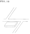
- step S1301 first in step S1301, as shown in Fig. 5, display coordinates P1 to P4 are obtained on the basis of the building shape data, sight point position, and sight line direction mentioned above and the respective coordinates are connected by straight lines.
- step S1302 line segments are connected in the height direction on the basis of height information, thereby forming a projection diagram of the building.
- step S1402 in step S1402, as shown in Fig. 7, display coordinates of each contour line are obtained on the basis of the mountain shape data, sight point position, and sight line direction mentioned above. The respective coordinates are connected by straight lines.
- step S1403 line segments are connected in the height direction on the basis of the height information.
- step S1401 The above processes are executed only a number of times corresponding to the number of contour lines and the resultant data is piled, thereby forming an image of a mountain (step S1401).
- Fig. 8A shows a state in which a projection diagram is formed onto the projection surface (screen S) of buildings A and B in the case that the buildings A and B are seen from the sight point position V.
- a surface FA of the building A and a surface FB of the building B are located in parallel with the screen S and a distance from the sight point position V to the surface FA is set to (a) and a distance from the sight point position V to the surface FB is set to (b).
- Fig. 9 is a flowchart showing a procedure for projection converting the buildings A and B onto the projection surface and, further, executing the hidden surface process.
- step S1601 the building A is "projection converted” (converted for projection) onto the screen S.
- a result of the projection conversion is shown in Fig. 8B.
- Fig. 8B shows a state in which the image information of the case that the building A is "projection converted" onto the screen S is obtained on the basis of the shape data of the building A and the preset sight point position and sight line direction.
- the image information is constituted by information which each pixel constructing the image has.
- the information which each pixel has in Fig. 8B is constituted by, for example, the color information that is obtained from the data structure of Fig. 2D and the distance value from the sight point position to an object to be displayed. However, only the distance value from the sight point position to the displaying object is shown in Figs. 8B and 8C for simplicity of explanation.
- the image of the building A on the screen S is constituted by pixels having the information (a) (distance value from the sight point position V) as shown in Fig. 8B and the information of the other pixels are set to, for example, ⁇ (infinite).
- step S1602 the image information of the case that the building B is projection converted onto the screen S is obtained. A result is shown in Fig. 8C.
- the distance value (a) of the pixel of the building A and the distance value (b) of the pixel of the building B are compared.
- a > b namely, when it is decided that the building A exists at a position farther than the building B when they are seen from the sight point position V
- the color information of the pixel of an overlapped portion G is specified by the color information of the building B and a corresponding image is drawn.
- the color information of the pixel of the overlapped portion G is specified by the color information of the building A and a corresponding image is drawn (steps S1605, S1606).
- the example of Fig. 8C relates to the case of b > a as shown in Fig. 8A.
- the intersecting point is hidden by a building B1 and information such as a shape of an intersecting point or the like having a high priority which is necessary when the user uses the navigation apparatus drops out.
- Fig. 12 is a block diagram showing a schematic construction of a navigation apparatus having a stereoscopic display function of buildings, mountains, etc. in the embodiment.
- the navigation apparatus of Fig. 12 is formed by adding a coordinates changing unit 9 to the construction of Fig. 1 and intends to change height information in the shape data of buildings, mountains, etc. by the coordinates changing unit 9 by a method, which will be explained later.
- the present position of the vehicle, the map data including the position designated by the operation unit 2, and the shape data of buildings, mountains, etc. are read out from the recording medium 4 and the projection converting process and the hidden surface process are executed in a manner similar to steps S1201 to S1209 in Fig. 3.
- the height information of the shape data of buildings, mountains, etc. is further changed as necessary.
- step S201 a check is made to see if link information indicative of the presence of the building exists in the map data to be displayed. If YES, the processing routine advances to step S202.
- step S202 a check is made to see if the overlapped portion with the image information of the road exists in the image constructing the building on the projection diagram formed in steps S1201 to S1209.
- a meshed portion C corresponds to the overlapped portion.
- step S202 the processing routine advances to step S203 and the individual image information of the overlapped portion is compared, namely, the distance value from the sight point position is compared.
- the processing routine advances to step S203 and the individual image information of the overlapped portion is compared, namely, the distance value from the sight point position is compared.
- step S204 a length from the top of the building to the lower edge of the overlapped portion is calculated.
- h corresponds to its length.
- step S205 only the length h calculated in step S204 is subtracted from the height information in the shape data of the building by the coordinates changing unit 9. That is, if the building is displayed lower than the original height by the length h, the road hidden by the building can be seen.
- step S206 image information of the case that the image is projected onto the projection surface is obtained on the basis of the changed shape data and map data.
- step S207 the changed image information is transferred to the image display unit 5 and a corresponding image is displayed.
- a display to clarify a road state near the intersecting point as shown in Fig. 14C can be performed.
- the embodiment can be also applied to a case where a road other than the road near the intersecting point is obscure by the building as shown in Fig. 10A. In this case, it will be obviously understood that the road state other than the road near the intersecting point can be clearly displayed as shown in Fig. 5.
- the embodiment can be also applied to a case of solving a problem such that, as shown in Fig. 10B, a building B2 existing at a position near the intersecting point is hidden by another building B3 and information regarding the building B2 as a landmark object for recognizing the intersecting point is obscure.
- the map data including the present position of the vehicle or the position designated by the operation unit and the shape data of buildings, mountains, etc. are read out from the recording medium 4.
- the projection converting process and the hidden surface process are executed in a manner similar to steps S1201 to S1209 in Fig. 12.
- step S401 a check is made to see if information of an intersecting point exists in the map data to be displayed.
- the above discriminating process can be realized by, for instance, previously adding information indicative of the presence of the intersecting point into the map data and by discriminating whether the information of the intersecting point exists in a range of the map data to be displayed.
- step S402 When it is decided that the information exists, a check is made in step S402 to see if link information of the buildings exists in a range of a predetermined distance from the coordinates constructing the intersecting point.
- link information of the building B2 exists in a predetermined distance D from coordinates 1 constructing the intersecting point.
- step S403 follows and a check is made to see if an overlapped portion with image information of another building exists in the image information of the corresponding building.
- a meshed portion corresponds to the overlapped portion.
- step S404 follows and each image information in the overlapped portion, namely, a distance value from the sight point position is compared.
- step S404 when the image information in the building existing at a position near the intersecting point, namely, an overlap of another building having a distance value smaller than the distance value of the building is detected, a height of overlapped portion is calculated in step S405.
- the height h corresponding to a distance from the top of the building B3 to the lower edge of the overlapped portion is calculated.
- step S406 only the height (h in Fig. 17B) corresponding to the overlapped portion is subtracted from the height information in the shape data of the building in which an overlapped distance value is small.
- step S407 image information of the case that the image is projected onto the projection surface is formed on the basis of the map data and the changed shaped data (Fig. 17C).
- step S408 the image information formed is transferred to the image display unit 5 and a display according to the image information is displayed.
- the buildings displayed as shown in Fig. 17B are displayed as shown in Fig. 17C and the buildings existing at a position near the intersecting point can be clearly displayed.
- steps S204, S205, S405, and S406 the length from the top of the building to the lower edge of the overlapped portion is subtracted from the original height information.
- the invention is not limited to this method but it will be obviously understood that a similar effect is derived by changing the height information of the building to a height such that the portion hidden by the buildings can be known or by setting the height information of the buildings into 0 irrespective of sizes of overlapped portion.
- the second embodiment to solve the subjects of the invention is now be shown below.
- the second embodiment relates to a navigation apparatus which can easily recognize the set route or the present position of the vehicle.
- the navigation apparatus is constructed as shown in Fig. 12 and is embodied by the processes of the control unit.
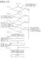
- FIG. 18 A flow for processes of the control unit 1 is shown in Fig. 18 and will be explained with reference to Figs. 19A to 19D as an example.
- the map data including the present position of the vehicle or the position designated by the operation unit 2 and the shape data of buildings, mountains, etc. are read out from the recording medium 4 and the projection converting process and the hidden surface process are executed in a manner similar to steps S1201 to S1209 in Fig. 3.
- step S701 a check is made to see if information of the set route (R in Fig. 19A) exists in the map data to be displayed.
- the route information which has been preset by the navigation apparatus can be also discriminated on a 2-dimensional map, it is also possible to discriminate whether the set route exists in the map information before the projection conversion is performed instead of after completion of the projection conversion.
- step S702 follows.
- step S702 a check is made to see if link information indicative of the presence of the building out of a range of a predetermined distance from the set route (hatched portion in a range of the predetermined distance D in Fig. 19A) exists.
- step S703 follows.
- step S703 the height information in the shape data of the relevant building is changed to a low height.
- step S704 image information when it is projected onto the projection surface is formed on the basis of the changed shape data and map data.
- steps S701 to S704 are executed with respect to all of the buildings existing out of the range of the predetermined distance from the set route.
- the image information formed is transferred to the image display unit 5 and a display according to the image information is performed in step S705.
- steps S701 to S705 By performing the processes in steps S701 to S705, for example, when the heights of buildings existing out of the range of the predetermined distance from the set route are set to low heights, they are displayed as shown in Fig. 19B, so that the buildings on the set route can be recognized easier than those in Fig. 10D.
- step S703 the height information with respect to the buildings out of the range of the predetermined distance from the set route has been changed.
- an effect such that the set route can be easily recognized is derived.
- step S701 and S702 By replacing the processes in steps S701 and S702 to a process for discriminating whether the buildings exist behind (or before) the present position of the vehicle when they are seen from the progressing direction of the vehicle, for example, the height information of the buildings existing in the hatched portion in Fig. 19C is changed and the buildings are displayed as shown in Fig. 19D.
- the present position P of the vehicle consequently, can be easily recognized and a situation of a map of the roads, buildings, etc. behind (or before) the present position P can be easily recognized.
- a desired range for instance, hatched portion in Fig. 20A
- height information of the buildings existing in the designated range can be changed.
- the buildings are displayed as shown in Fig. 20B and it will be obviously understood that a situation of a map of the roads, buildings, etc. in a range which the operator wants to know can be clarified.
- the important information on the map hidden by the buildings, mountains, etc. which were stereoscopically displayed can be preferentially recognized or the set route or the present position of the vehicle can be easily recognized.
- the road information hidden by the buildings which were stereoscopically displayed can be preferentially recognized
- the building standing as a landmark object at a position near the intersecting point is hidden by another building which was stereoscopically displayed, the building standing as a landmark object can be preferentially recognized.
- the present position of the vehicle can be easily recognized on the map on which buildings, mountains, etc. are stereoscopically displayed, and a situation of the map of the roads, buildings, or the like on the front side (or rear side) can be clarified.
- the information regarding the set route on the map on which buildings, mountains, etc. are stereoscopically displayed can be easily recognized.
- a situation of the map of the roads, buildings, etc. in a desired range on the map on which buildings, mountains, etc. are stereoscopically displayed can be clarified.
Landscapes
- Engineering & Computer Science (AREA)
- Radar, Positioning & Navigation (AREA)
- Remote Sensing (AREA)
- Automation & Control Theory (AREA)
- Physics & Mathematics (AREA)
- General Physics & Mathematics (AREA)
- Navigation (AREA)
- Instructional Devices (AREA)
- Traffic Control Systems (AREA)
Applications Claiming Priority (3)
| Application Number | Priority Date | Filing Date | Title |
|---|---|---|---|
| JP13078996A JP3798469B2 (ja) | 1996-04-26 | 1996-04-26 | ナビゲーション装置 |
| JP13078996 | 1996-04-26 | ||
| JP130789/96 | 1996-04-26 |
Publications (3)
| Publication Number | Publication Date |
|---|---|
| EP0803706A2 true EP0803706A2 (de) | 1997-10-29 |
| EP0803706A3 EP0803706A3 (de) | 1998-12-23 |
| EP0803706B1 EP0803706B1 (de) | 2004-06-30 |
Family
ID=15042732
Family Applications (1)
| Application Number | Title | Priority Date | Filing Date |
|---|---|---|---|
| EP97106642A Expired - Lifetime EP0803706B1 (de) | 1996-04-26 | 1997-04-22 | Navigationsvorrichtung mit Formveränderungsanzeigefunktion |
Country Status (4)
| Country | Link |
|---|---|
| US (1) | US5999879A (de) |
| EP (1) | EP0803706B1 (de) |
| JP (1) | JP3798469B2 (de) |
| DE (1) | DE69729684T2 (de) |
Cited By (14)
| Publication number | Priority date | Publication date | Assignee | Title |
|---|---|---|---|---|
| EP1024467A3 (de) * | 1999-01-29 | 2001-11-14 | Hitachi, Ltd. | Verfahren zur stereoskopischen Kartenanzeige und Navigationssystem zur Verwendung bei dem Verfahren |
| WO2002016874A1 (de) * | 2000-08-24 | 2002-02-28 | Siemens Aktiengesellschaft | Verfahren zum gewinnen einer kartendarstellung und navigationsgerät |
| EP1085299A3 (de) * | 1999-09-14 | 2003-12-10 | Alpine Electronics, Inc. | Navigationsvorrichtung |
| US6871143B2 (en) * | 2002-05-30 | 2005-03-22 | Alpine Electronics, Inc. | Navigation apparatus |
| EP1126245A3 (de) * | 2000-02-14 | 2005-05-11 | Matsushita Electric Industrial Co., Ltd. | Vorrichtung und Verfahren zum Ändern von Karteninformationen |
| WO2007031361A1 (de) * | 2005-09-12 | 2007-03-22 | Robert Bosch Gmbh | Verfahren zur dreidimensionalen darstellung einer vektorkarte eines bildschirm-navigationssystems |
| EP1298414A4 (de) * | 2000-07-04 | 2007-08-08 | Mitsubishi Electric Corp | Verfahren zum Anzeigen einer Landmarke für eine Navigationsvorrichtung |
| DE102007022512A1 (de) * | 2007-05-14 | 2008-11-20 | Continental Automotive Gmbh | Verfahren und Vorrichtung zum Ermitteln dreidimensionaler Straßenkartendaten |
| WO2009132679A1 (en) * | 2008-05-02 | 2009-11-05 | Tomtom International B.V. | Navigation device & method |
| EP2075543A3 (de) * | 2007-12-26 | 2010-04-14 | Aisin AW Co., Ltd. | Dreidimensionale Kartenanzeige-Navigationsvorrichtung, dreidimensionales Kartenanzeigesystem und dreidimensionales Kartenanzeigeprogramm |
| CN102538802A (zh) * | 2010-12-30 | 2012-07-04 | 上海博泰悦臻电子设备制造有限公司 | 三维导航显示方法以及相关装置 |
| CN104075719A (zh) * | 2013-03-26 | 2014-10-01 | 高德信息技术有限公司 | 一种三维导航方法和装置 |
| EP2972095A4 (de) * | 2013-03-14 | 2017-04-05 | Robert Bosch GmbH | System und verfahren zur kontextabhängigen detailniveaueinstellung von navigationskarten und -systemen |
| CN108885845A (zh) * | 2016-03-24 | 2018-11-23 | 三菱电机株式会社 | 辅助图像显示装置、辅助图像显示方法和辅助图像显示程序 |
Families Citing this family (46)
| Publication number | Priority date | Publication date | Assignee | Title |
|---|---|---|---|---|
| JP2000148010A (ja) * | 1998-11-06 | 2000-05-26 | Matsushita Electric Ind Co Ltd | 道路地図表示装置及び道路地図表示方法 |
| US6710774B1 (en) | 1999-05-12 | 2004-03-23 | Denso Corporation | Map display device |
| JP3967866B2 (ja) * | 2000-04-28 | 2007-08-29 | パイオニア株式会社 | ナビゲーション装置及びナビゲーションプログラムがコンピュータで読取可能に記録された情報記録媒体 |
| JP4587601B2 (ja) * | 2000-05-30 | 2010-11-24 | パナソニック株式会社 | 地図表示装置、地図表示方法、地図表示装置において用いられるコンピュータプログラム、及びプログラム記録媒体 |
| CA2317336A1 (en) * | 2000-09-06 | 2002-03-06 | David Cowperthwaite | Occlusion resolution operators for three-dimensional detail-in-context |
| JP2001174274A (ja) * | 2000-10-13 | 2001-06-29 | Fujitsu Ten Ltd | 地図表示方法および装置 |
| CA2328795A1 (en) | 2000-12-19 | 2002-06-19 | Advanced Numerical Methods Ltd. | Applications and performance enhancements for detail-in-context viewing technology |
| US6477460B2 (en) * | 2001-02-27 | 2002-11-05 | Metro One Telecommunications, Inc. | Process and system for the annotation of machine-generated directions with easily recognized landmarks and other relevant information |
| US8416266B2 (en) | 2001-05-03 | 2013-04-09 | Noregin Assetts N.V., L.L.C. | Interacting with detail-in-context presentations |
| CA2345803A1 (en) | 2001-05-03 | 2002-11-03 | Idelix Software Inc. | User interface elements for pliable display technology implementations |
| US9760235B2 (en) | 2001-06-12 | 2017-09-12 | Callahan Cellular L.L.C. | Lens-defined adjustment of displays |
| US7084886B2 (en) | 2002-07-16 | 2006-08-01 | Idelix Software Inc. | Using detail-in-context lenses for accurate digital image cropping and measurement |
| WO2002101534A1 (en) | 2001-06-12 | 2002-12-19 | Idelix Software Inc. | Graphical user interface with zoom for detail-in-context presentations |
| JP2003106862A (ja) * | 2001-09-28 | 2003-04-09 | Pioneer Electronic Corp | 地図描画装置 |
| CA2361341A1 (en) | 2001-11-07 | 2003-05-07 | Idelix Software Inc. | Use of detail-in-context presentation on stereoscopically paired images |
| JP3933929B2 (ja) * | 2001-12-28 | 2007-06-20 | アルパイン株式会社 | ナビゲーション装置 |
| US7251622B2 (en) * | 2002-01-16 | 2007-07-31 | Hong Fu Jin Precision Ind. (Shenzhen) Co., Ltd. | System and method for searching for information on inventory with virtual warehouses |
| CA2370752A1 (en) | 2002-02-05 | 2003-08-05 | Idelix Software Inc. | Fast rendering of pyramid lens distorted raster images |
| US8120624B2 (en) | 2002-07-16 | 2012-02-21 | Noregin Assets N.V. L.L.C. | Detail-in-context lenses for digital image cropping, measurement and online maps |
| CA2393887A1 (en) | 2002-07-17 | 2004-01-17 | Idelix Software Inc. | Enhancements to user interface for detail-in-context data presentation |
| CA2406131A1 (en) | 2002-09-30 | 2004-03-30 | Idelix Software Inc. | A graphical user interface using detail-in-context folding |
| CA2449888A1 (en) | 2003-11-17 | 2005-05-17 | Idelix Software Inc. | Navigating large images using detail-in-context fisheye rendering techniques |
| CA2411898A1 (en) | 2002-11-15 | 2004-05-15 | Idelix Software Inc. | A method and system for controlling access to detail-in-context presentations |
| US7486302B2 (en) | 2004-04-14 | 2009-02-03 | Noregin Assets N.V., L.L.C. | Fisheye lens graphical user interfaces |
| US8106927B2 (en) | 2004-05-28 | 2012-01-31 | Noregin Assets N.V., L.L.C. | Graphical user interfaces and occlusion prevention for fisheye lenses with line segment foci |
| US9317945B2 (en) | 2004-06-23 | 2016-04-19 | Callahan Cellular L.L.C. | Detail-in-context lenses for navigation |
| US7714859B2 (en) | 2004-09-03 | 2010-05-11 | Shoemaker Garth B D | Occlusion reduction and magnification for multidimensional data presentations |
| US7995078B2 (en) | 2004-09-29 | 2011-08-09 | Noregin Assets, N.V., L.L.C. | Compound lenses for multi-source data presentation |
| US7580036B2 (en) | 2005-04-13 | 2009-08-25 | Catherine Montagnese | Detail-in-context terrain displacement algorithm with optimizations |
| US8031206B2 (en) | 2005-10-12 | 2011-10-04 | Noregin Assets N.V., L.L.C. | Method and system for generating pyramid fisheye lens detail-in-context presentations |
| US7983473B2 (en) | 2006-04-11 | 2011-07-19 | Noregin Assets, N.V., L.L.C. | Transparency adjustment of a presentation |
| US8566028B2 (en) * | 2006-11-27 | 2013-10-22 | International Business Machines Corporation | Apparatus, system, and method for autonomously determining a set of destinations |
| US8253736B2 (en) * | 2007-01-29 | 2012-08-28 | Microsoft Corporation | Reducing occlusions in oblique views |
| JP5070421B2 (ja) * | 2007-05-21 | 2012-11-14 | 株式会社ジオ技術研究所 | 地図表示装置 |
| US9026938B2 (en) | 2007-07-26 | 2015-05-05 | Noregin Assets N.V., L.L.C. | Dynamic detail-in-context user interface for application access and content access on electronic displays |
| KR100889469B1 (ko) * | 2008-04-23 | 2009-03-19 | 팅크웨어(주) | 도로 정보에 기초하여 3차원 지도를 표시하는 시스템 및방법 |
| WO2009132676A1 (en) * | 2008-05-02 | 2009-11-05 | Tom Tom International B.V. | A navigation device and method for emphasising a map route |
| CN101983315A (zh) * | 2008-05-29 | 2011-03-02 | 通腾科技股份有限公司 | 在数字地图图像上显示路径信息 |
| US8411092B2 (en) * | 2010-06-14 | 2013-04-02 | Nintendo Co., Ltd. | 2D imposters for simplifying processing of plural animation objects in computer graphics generation |
| EP2711890B1 (de) * | 2011-05-31 | 2018-07-11 | Rakuten, Inc. | Informationsbereitstellungsvorrichtung, informationsbereitstellungsverfahren, verarbeitungsprogramm zur informationsbereitstellung, aufzeichnungsmedium zur aufzeichnung eines verarbeitungsprogramms zur informationsbereitstellung und informationsbereitstellungssystem |
| US20150029214A1 (en) * | 2012-01-19 | 2015-01-29 | Pioneer Corporation | Display device, control method, program and storage medium |
| DE102013000879A1 (de) | 2013-01-10 | 2014-07-24 | Volkswagen Aktiengesellschaft | Navigationsvorrichtung für ein bewegliches Objekt und Verfahren zur Erzeugung eines Anzeigesignals für eine Navigationsvorrichtung für ein bewegliches Objekt |
| JP6533075B2 (ja) * | 2015-03-18 | 2019-06-19 | アイシン・エィ・ダブリュ株式会社 | 地図画像表示装置、ナビゲーション装置、地図画像表示プログラム、及び地図画像表示方法 |
| US11189089B2 (en) | 2020-01-08 | 2021-11-30 | Mapbox, Inc. | Dynamic building extrusion in electronic maps |
| CN114549775A (zh) * | 2022-01-13 | 2022-05-27 | 阿里巴巴新加坡控股有限公司 | 电子地图的渲染方法、装置和计算机程序产品 |
| CN114708394B (zh) * | 2022-03-31 | 2026-02-03 | 阿里巴巴(中国)有限公司 | 地图渲染方法、电子设备及计算机存储介质 |
Family Cites Families (11)
| Publication number | Priority date | Publication date | Assignee | Title |
|---|---|---|---|---|
| JPS57186111A (en) * | 1981-05-13 | 1982-11-16 | Nissan Motor Co Ltd | Map display device for vehicle |
| JPH0690596B2 (ja) * | 1985-04-30 | 1994-11-14 | 日本電装株式会社 | 電子地図表示装置 |
| GB2176644A (en) * | 1985-05-28 | 1986-12-31 | John Russell Henderson | Maps |
| DE3736386A1 (de) * | 1986-10-27 | 1988-07-14 | Pioneer Electronic Corp | Fahrzeugpeilverfahren |
| JP3108122B2 (ja) * | 1991-04-25 | 2000-11-13 | パイオニア株式会社 | 車載ナビゲーション装置 |
| DE69434693T2 (de) * | 1993-12-27 | 2006-08-24 | Nissan Motor Co., Ltd., Yokohama | Fahrzeugzielführungsvorrichtung und -verfahren unter Verwendung einer Anzeigeeinheit |
| EP0678731B1 (de) * | 1994-04-15 | 1999-06-30 | Nissan Motor Co., Ltd. | Fahrzeug-Navigationssystem |
| JPH07306637A (ja) * | 1994-05-12 | 1995-11-21 | Sony Corp | 複合電子装置 |
| JP3371605B2 (ja) * | 1995-04-19 | 2003-01-27 | 日産自動車株式会社 | 大気効果表示機能付き鳥瞰図表示ナビゲーションシステム |
| KR100235239B1 (ko) * | 1995-09-29 | 1999-12-15 | 모리 하루오 | 가형정보의 출력장치, 가형정보의 출력방법, 지도표시장치, 지도표시방법, 네비게이션장치 및 네비게이션방법 |
| KR100235240B1 (ko) * | 1995-10-31 | 1999-12-15 | 모리 하루오 | 네비게이션(navigation) 장치 |
-
1996
- 1996-04-26 JP JP13078996A patent/JP3798469B2/ja not_active Expired - Lifetime
-
1997
- 1997-04-18 US US08/839,823 patent/US5999879A/en not_active Expired - Lifetime
- 1997-04-22 DE DE69729684T patent/DE69729684T2/de not_active Expired - Lifetime
- 1997-04-22 EP EP97106642A patent/EP0803706B1/de not_active Expired - Lifetime
Cited By (18)
| Publication number | Priority date | Publication date | Assignee | Title |
|---|---|---|---|---|
| US6587784B1 (en) | 1999-01-29 | 2003-07-01 | Hitachi, Ltd. | Stereoscopic map-display method and navigation system using the method |
| EP1024467A3 (de) * | 1999-01-29 | 2001-11-14 | Hitachi, Ltd. | Verfahren zur stereoskopischen Kartenanzeige und Navigationssystem zur Verwendung bei dem Verfahren |
| KR100745116B1 (ko) * | 1999-01-29 | 2007-08-01 | 가부시끼가이샤 히다치 세이사꾸쇼 | 입체지도표시방법 및 이 방법을 사용한 네비게이션장치 |
| EP1085299A3 (de) * | 1999-09-14 | 2003-12-10 | Alpine Electronics, Inc. | Navigationsvorrichtung |
| EP1126245A3 (de) * | 2000-02-14 | 2005-05-11 | Matsushita Electric Industrial Co., Ltd. | Vorrichtung und Verfahren zum Ändern von Karteninformationen |
| EP1298414A4 (de) * | 2000-07-04 | 2007-08-08 | Mitsubishi Electric Corp | Verfahren zum Anzeigen einer Landmarke für eine Navigationsvorrichtung |
| US6678610B2 (en) | 2000-08-24 | 2004-01-13 | Siemens Aktiengesellschaft | Method for obtaining a map representation, and a navigation device |
| WO2002016874A1 (de) * | 2000-08-24 | 2002-02-28 | Siemens Aktiengesellschaft | Verfahren zum gewinnen einer kartendarstellung und navigationsgerät |
| US6871143B2 (en) * | 2002-05-30 | 2005-03-22 | Alpine Electronics, Inc. | Navigation apparatus |
| WO2007031361A1 (de) * | 2005-09-12 | 2007-03-22 | Robert Bosch Gmbh | Verfahren zur dreidimensionalen darstellung einer vektorkarte eines bildschirm-navigationssystems |
| DE102007022512A1 (de) * | 2007-05-14 | 2008-11-20 | Continental Automotive Gmbh | Verfahren und Vorrichtung zum Ermitteln dreidimensionaler Straßenkartendaten |
| EP2075543A3 (de) * | 2007-12-26 | 2010-04-14 | Aisin AW Co., Ltd. | Dreidimensionale Kartenanzeige-Navigationsvorrichtung, dreidimensionales Kartenanzeigesystem und dreidimensionales Kartenanzeigeprogramm |
| WO2009132679A1 (en) * | 2008-05-02 | 2009-11-05 | Tomtom International B.V. | Navigation device & method |
| CN102538802A (zh) * | 2010-12-30 | 2012-07-04 | 上海博泰悦臻电子设备制造有限公司 | 三维导航显示方法以及相关装置 |
| CN102538802B (zh) * | 2010-12-30 | 2016-06-22 | 上海博泰悦臻电子设备制造有限公司 | 三维导航显示方法以及相关装置 |
| EP2972095A4 (de) * | 2013-03-14 | 2017-04-05 | Robert Bosch GmbH | System und verfahren zur kontextabhängigen detailniveaueinstellung von navigationskarten und -systemen |
| CN104075719A (zh) * | 2013-03-26 | 2014-10-01 | 高德信息技术有限公司 | 一种三维导航方法和装置 |
| CN108885845A (zh) * | 2016-03-24 | 2018-11-23 | 三菱电机株式会社 | 辅助图像显示装置、辅助图像显示方法和辅助图像显示程序 |
Also Published As
| Publication number | Publication date |
|---|---|
| JPH09292833A (ja) | 1997-11-11 |
| EP0803706A3 (de) | 1998-12-23 |
| DE69729684T2 (de) | 2005-07-21 |
| US5999879A (en) | 1999-12-07 |
| JP3798469B2 (ja) | 2006-07-19 |
| EP0803706B1 (de) | 2004-06-30 |
| DE69729684D1 (de) | 2004-08-05 |
Similar Documents
| Publication | Publication Date | Title |
|---|---|---|
| EP0803706B1 (de) | Navigationsvorrichtung mit Formveränderungsanzeigefunktion | |
| KR102022388B1 (ko) | 실세계 물체 정보를 이용한 카메라 공차 보정 시스템 및 방법 | |
| EP0867690B1 (de) | Vorrichtung und System zum Etikettieren digitaler Bilder | |
| JP4832596B2 (ja) | 俯瞰画像生成装置、俯瞰画像生成方法および俯瞰画像生成プログラム | |
| JP4959812B2 (ja) | ナビゲーション装置 | |
| US20180224286A1 (en) | Methods and systems to convey autonomous/semi-autonomous feature available roadways | |
| US20100250116A1 (en) | Navigation device | |
| JP2019508677A (ja) | 地図を使用した車両構成部品の制御 | |
| WO2011023244A1 (en) | Method and system of processing data gathered using a range sensor | |
| JP2008139295A (ja) | カメラを用いた車両用ナビゲーションの交差点案内装置及びその方法 | |
| JP3620918B2 (ja) | ナビゲーション装置の地図表示方法およびナビゲーション装置 | |
| JP2011170599A (ja) | 屋外構造物計測装置及び屋外構造物計測方法 | |
| WO2009084129A1 (ja) | ナビゲーション装置 | |
| JP6723744B2 (ja) | ナビ情報提供システム及びナビ情報提供装置 | |
| JP2014074627A (ja) | 車両用ナビゲーションシステム | |
| JP2021071885A (ja) | 領域切り出し方法および領域切り出しプログラム | |
| JPH09304106A (ja) | ナビゲーションシステム | |
| JP2008128827A (ja) | ナビゲーション装置およびナビゲーション方法ならびにそのプログラム | |
| US20250157223A1 (en) | Traffic flow measurement system and traffic flow measurement method | |
| US20250182617A1 (en) | Traffic flow measurement system and traffic flow measurement method | |
| JP7046555B2 (ja) | 車載装置、サーバ、表示方法、送信方法 | |
| JPH08255245A (ja) | ランドマーク認識装置およびランドマーク認識方法 | |
| JP2014232196A (ja) | ナビゲーション装置、道路地図作成方法および道路地図作成プログラム | |
| JP5231595B2 (ja) | ナビゲーション装置 | |
| KR100359342B1 (ko) | 씨씨티브 카메라의 패닝, 틸팅, 주밍 변환에 따른검지영역 자동설정 시스템 |
Legal Events
| Date | Code | Title | Description |
|---|---|---|---|
| PUAI | Public reference made under article 153(3) epc to a published international application that has entered the european phase |
Free format text: ORIGINAL CODE: 0009012 |
|
| AK | Designated contracting states |
Kind code of ref document: A2 Designated state(s): DE FR GB |
|
| PUAL | Search report despatched |
Free format text: ORIGINAL CODE: 0009013 |
|
| AK | Designated contracting states |
Kind code of ref document: A3 Designated state(s): DE FR GB |
|
| 17P | Request for examination filed |
Effective date: 19990521 |
|
| GRAP | Despatch of communication of intention to grant a patent |
Free format text: ORIGINAL CODE: EPIDOSNIGR1 |
|
| GRAS | Grant fee paid |
Free format text: ORIGINAL CODE: EPIDOSNIGR3 |
|
| GRAA | (expected) grant |
Free format text: ORIGINAL CODE: 0009210 |
|
| AK | Designated contracting states |
Kind code of ref document: B1 Designated state(s): DE FR GB |
|
| REG | Reference to a national code |
Ref country code: GB Ref legal event code: FG4D |
|
| REF | Corresponds to: |
Ref document number: 69729684 Country of ref document: DE Date of ref document: 20040805 Kind code of ref document: P |
|
| ET | Fr: translation filed | ||
| PLBE | No opposition filed within time limit |
Free format text: ORIGINAL CODE: 0009261 |
|
| STAA | Information on the status of an ep patent application or granted ep patent |
Free format text: STATUS: NO OPPOSITION FILED WITHIN TIME LIMIT |
|
| REG | Reference to a national code |
Ref country code: GB Ref legal event code: 746 Effective date: 20050504 |
|
| 26N | No opposition filed |
Effective date: 20050331 |
|
| REG | Reference to a national code |
Ref country code: FR Ref legal event code: D6 |
|
| REG | Reference to a national code |
Ref country code: FR Ref legal event code: PLFP Year of fee payment: 20 |
|
| PGFP | Annual fee paid to national office [announced via postgrant information from national office to epo] |
Ref country code: FR Payment date: 20160309 Year of fee payment: 20 |
|
| PGFP | Annual fee paid to national office [announced via postgrant information from national office to epo] |
Ref country code: DE Payment date: 20160419 Year of fee payment: 20 Ref country code: GB Payment date: 20160420 Year of fee payment: 20 |
|
| REG | Reference to a national code |
Ref country code: DE Ref legal event code: R071 Ref document number: 69729684 Country of ref document: DE |
|
| REG | Reference to a national code |
Ref country code: GB Ref legal event code: PE20 Expiry date: 20170421 |
|
| PG25 | Lapsed in a contracting state [announced via postgrant information from national office to epo] |
Ref country code: GB Free format text: LAPSE BECAUSE OF EXPIRATION OF PROTECTION Effective date: 20170421 |