EP0803644B1 - Viertaktbrennkraftmaschine in V Bauart für Motorrad - Google Patents
Viertaktbrennkraftmaschine in V Bauart für Motorrad Download PDFInfo
- Publication number
- EP0803644B1 EP0803644B1 EP97105569A EP97105569A EP0803644B1 EP 0803644 B1 EP0803644 B1 EP 0803644B1 EP 97105569 A EP97105569 A EP 97105569A EP 97105569 A EP97105569 A EP 97105569A EP 0803644 B1 EP0803644 B1 EP 0803644B1
- Authority
- EP
- European Patent Office
- Prior art keywords
- cylinder
- head
- motorcycle
- mating surface
- stroke
- Prior art date
- Legal status (The legal status is an assumption and is not a legal conclusion. Google has not performed a legal analysis and makes no representation as to the accuracy of the status listed.)
- Expired - Lifetime
Links
- 230000013011 mating Effects 0.000 claims description 21
- 230000000712 assembly Effects 0.000 claims description 14
- 238000000429 assembly Methods 0.000 claims description 14
- 230000007246 mechanism Effects 0.000 description 8
- 239000000725 suspension Substances 0.000 description 4
- 230000005484 gravity Effects 0.000 description 3
- 239000002828 fuel tank Substances 0.000 description 2
- 230000002146 bilateral effect Effects 0.000 description 1
- 230000007547 defect Effects 0.000 description 1
- 239000000446 fuel Substances 0.000 description 1
- 239000000203 mixture Substances 0.000 description 1
Images

Classifications
-
- F—MECHANICAL ENGINEERING; LIGHTING; HEATING; WEAPONS; BLASTING
- F02—COMBUSTION ENGINES; HOT-GAS OR COMBUSTION-PRODUCT ENGINE PLANTS
- F02B—INTERNAL-COMBUSTION PISTON ENGINES; COMBUSTION ENGINES IN GENERAL
- F02B61/00—Adaptations of engines for driving vehicles or for driving propellers; Combinations of engines with gearing
- F02B61/02—Adaptations of engines for driving vehicles or for driving propellers; Combinations of engines with gearing for driving cycles
-
- F—MECHANICAL ENGINEERING; LIGHTING; HEATING; WEAPONS; BLASTING
- F02—COMBUSTION ENGINES; HOT-GAS OR COMBUSTION-PRODUCT ENGINE PLANTS
- F02B—INTERNAL-COMBUSTION PISTON ENGINES; COMBUSTION ENGINES IN GENERAL
- F02B75/00—Other engines
- F02B75/16—Engines characterised by number of cylinders, e.g. single-cylinder engines
- F02B75/18—Multi-cylinder engines
- F02B75/22—Multi-cylinder engines with cylinders in V, fan, or star arrangement
-
- F—MECHANICAL ENGINEERING; LIGHTING; HEATING; WEAPONS; BLASTING
- F02—COMBUSTION ENGINES; HOT-GAS OR COMBUSTION-PRODUCT ENGINE PLANTS
- F02F—CYLINDERS, PISTONS OR CASINGS, FOR COMBUSTION ENGINES; ARRANGEMENTS OF SEALINGS IN COMBUSTION ENGINES
- F02F7/00—Casings, e.g. crankcases
- F02F7/006—Camshaft or pushrod housings
-
- F—MECHANICAL ENGINEERING; LIGHTING; HEATING; WEAPONS; BLASTING
- F02—COMBUSTION ENGINES; HOT-GAS OR COMBUSTION-PRODUCT ENGINE PLANTS
- F02B—INTERNAL-COMBUSTION PISTON ENGINES; COMBUSTION ENGINES IN GENERAL
- F02B75/00—Other engines
- F02B75/02—Engines characterised by their cycles, e.g. six-stroke
- F02B2075/022—Engines characterised by their cycles, e.g. six-stroke having less than six strokes per cycle
- F02B2075/027—Engines characterised by their cycles, e.g. six-stroke having less than six strokes per cycle four
-
- F—MECHANICAL ENGINEERING; LIGHTING; HEATING; WEAPONS; BLASTING
- F02—COMBUSTION ENGINES; HOT-GAS OR COMBUSTION-PRODUCT ENGINE PLANTS
- F02B—INTERNAL-COMBUSTION PISTON ENGINES; COMBUSTION ENGINES IN GENERAL
- F02B75/00—Other engines
- F02B75/16—Engines characterised by number of cylinders, e.g. single-cylinder engines
- F02B75/18—Multi-cylinder engines
- F02B2075/1804—Number of cylinders
- F02B2075/1808—Number of cylinders two
-
- F—MECHANICAL ENGINEERING; LIGHTING; HEATING; WEAPONS; BLASTING
- F02—COMBUSTION ENGINES; HOT-GAS OR COMBUSTION-PRODUCT ENGINE PLANTS
- F02B—INTERNAL-COMBUSTION PISTON ENGINES; COMBUSTION ENGINES IN GENERAL
- F02B2275/00—Other engines, components or details, not provided for in other groups of this subclass
- F02B2275/18—DOHC [Double overhead camshaft]
-
- F—MECHANICAL ENGINEERING; LIGHTING; HEATING; WEAPONS; BLASTING
- F02—COMBUSTION ENGINES; HOT-GAS OR COMBUSTION-PRODUCT ENGINE PLANTS
- F02F—CYLINDERS, PISTONS OR CASINGS, FOR COMBUSTION ENGINES; ARRANGEMENTS OF SEALINGS IN COMBUSTION ENGINES
- F02F1/00—Cylinders; Cylinder heads
- F02F1/24—Cylinder heads
- F02F2001/244—Arrangement of valve stems in cylinder heads
- F02F2001/245—Arrangement of valve stems in cylinder heads the valve stems being orientated at an angle with the cylinder axis
Definitions
- the present invention relates to a four-stroke-cycle V-type engine of a motorcycle and more particularly to a cylinder head of such engine in which cylinder blocks are arranged so as to provide a V-shape along the longitudinal direction, i.e. running direction, of a motorcycle body.
- valves are arranged for intaking an air/fuel mixture gas and exhausting an exhaust gas
- an arrangement of an engine in which a plurality of cylinder blocks are arranged so as to provide V-shape along the longitudinal or lateral direction of a motorcycle body.
- the above-mentioned valves are arranged to head portions of the cylinder blocks and covered by head covers.
- An object of the present invention is to substantially eliminate defects or drawbacks encountered in the prior art and to provide a four-stroke-cycle V-type engine of a motorcycle arranged between front and rear wheels thereof, comprising a crank case in which a crank shaft is arranged and a plurality of cylinder assemblies operatively connected to the crank shaft and including front-side cylinder assembly and a rear-side cylinder assembly along a longitudinal direction of a motorcycle body each of the cylinder assemblies being composed of a cylinder block, a cylinder head mounted to a head portion of the cylinder block and a head cover covering the cylinder head, the cylinder assemblies being arranged so as to provide V-shapes along the longitudinal direction of the motorcycle body, wherein a mating surface formed between the head cover and the cylinder head of at least the front-side cylinder assembly of the plural cylinder assemblies has an inclination obliquely downward towards the front wheel side with respect to a mating surface formed between the cylinder head and the cylinder block of the front-side cylinder assembly.
- the front-side cylinder assembly is disposed at a portion near the front wheel.
- a mating surface may be designed to be disposed between the head cover and the cylinder head of the rear-side cylinder assembly of the plural cylinder assemblies so as to have an inclination obliquely downward towards the front wheel side with respect to a mating surface formed between the cylinder head and the cylinder block of the rear-side cylinder assembly.
- the cover-side mating surface on the front-side cylinder assembly is designed so as to provide an inclination obliquely downward towards the front wheel side with respect to the block-side mating surface, a space can be sufficiently ensured between the front-side head cover and the front wheel even in a state that a suspension mechanism for the front wheel is maximally compressed, and therefore, it is not necessary to extend the wheel base more than needed, thus improving the maneuverability of the motorcycle.
- the engine can be arranged properly so that the center of the gravity thereof can be shifted to a proper position to achieve the load balance to the front wheel, thus also improving the maneuverability of the motorcycle.
- the cylinder heads can be made compact and light without damaging the function of a valve moving mechanism.
- a motorcycle 1 has a body frame 2 and an engine 3 mounted to a front lower portion of the body frame 2.
- a fuel tank 4 is disposed above the engine 3 and a rider's seat 5 is positioned at a portion rear-side the fuel tank 4.
- the front portion of the motorcycle 1 is covered by a cowling 6 to reduce an air resistance to the motorcycle and to protect the rider from wind pressure during the running thereof.
- a head pipe 7 is mounted to the front portion of the body frame 2, and a steering assembly 10 including a pair of front forks 9 and front fenders 19, which are equipped with suspension mechanisms rotatably supporting the front wheel 8, is also mounted.
- the steering assembly 10 also includes a handle bar, not shown.
- the body frame 2 has, for example, twin-tube type structure having a lateral pair of main frame elements 2a which are widened in the bilateral direction, i.e. width direction, of the motorcycle body at a portion immediately rear side of the head pipe 7 and seat rails 2b extending rearward from substantially central portions of the main frame elements 2a, and pivot portions 2c are formed to the rear lower portions of the main frame elements 2a.
- a pivot pin 11 is disposed laterally between the pivot portions 2c and a swing arm 12 is pivoted to the pivot pin 11 to be swingable and a rear wheel 13 is supported to the swing arm to be rotatable.
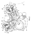
- the engine 3 comprises a crank case 14 and cylinder assemblies 18 composed of cylinder blocks 15, cylinder heads 16 and head covers 17, and in the present embodiment, two front and rear cylinder assemblies 18F and 18R are arranged so as to provide a V-shape structure in the longitudinal direction of the motorcycle body, i.e. running direction thereof.
- the cylinder blocks 15 include two front and rear cylinder blocks 15F and 15R
- the cylinder heads 16 includes two front and rear cylinder heads 16F and 16R
- the head covers 17 includes two front and rear cylinder covers 17F and 17R, respectively.
- the engine 3 is a four-stroke-cycle engine in which two camshafts 23 and 24 for intake and exhaust valves 20 and 21, respectively, are arranged to upper portions of the cylinder heads 16 and above these valves 20 and 21, and DOHC-type (double-overhead-camshaft) valve moving mechanisms 25 for opening or closing these valves 20 and 21 are also disposed.
- DOHC-type double-overhead-camshaft
- Intake passages 26 are formed to a rear side of the front-side cylinder head 16F and a front side of the rear-side cylinder head 16R, and an intake system, not shown, is connected to the intake passages 26.
- Exhaust passages 27 are also formed to a front side of the front-side cylinder head 16F and a rear side of the rear-side cylinder head 16R, and exhaust pipes 22a are connected to the exhaust passages 27, respectively, and then connected to a muffler 22b, the exhaust pipes 22a and the muffler 22b constituting an engine exhaust system.
- crank shaft 28 extending in a direction normal to the running direction of the motorcycle 1.
- connection rods 29 has a large diameter end portion 29a coupled to the crank shaft 28 and has a small diameter end portion 29b coupled to a piston 31 through a piston pin 30.
- the piston 31 is disposed so as to reciprocate in a cylinder 32 formed to each of the cylinder blocks 16, and the reciprocal stroke of the piston 31 is transmitted to the crank shaft 28 through the connection rod 29 to thereby rotate the crank shaft 28.
- An idler shaft 33 is arranged above the crank shaft 28 to be parallel thereto.
- a cam drive sprocket 34 is mounted to the crank shaft 28 and a cam driven sprocket 35 is also mounted to the idler shaft 33, the cam drive sprocket 34 and the cam driven sprocket 35 being operatively coupled to each other.
- An idler drive gear 36 is also mounted to the idler shaft 33.
- the intake valves 20 and the intake camshafts 23 for opening or closing the intake valves 23 are disposed above the intake passages 26 of the front- and rear-side cylinder heads 16F and 16R, respectively, and the exhaust valves 21 and the exhaust camshafts 24 for opening or closing the exhaust valves 21 are also disposed above the exhaust passages 27 of the front- and rear-side cylinder heads 16F and 16R, respectively.
- Cam sprockets 37 are mounted to respective one ends of these camshafts 23 and 24, and the cam sprockets 37 are operatively coupled together through the idler driven gears 38 which are operatively connected to the idler drive gears 36 mounted to the idler shaft 33 by means of cam chains 39. According to such arrangement, when the crank shaft 28 is rotated, the rotating motion is transmitted to the camshafts 23 and 24 through the idler shaft 33, the valve moving mechanisms 25 being thereby driven.
- the upper portions of the respective valve moving mechanisms 25 are covered by the front-side and rear-side head covers 17F and 17R, and a mating surface 40 (cover-side mating surface) of the head cover 17F and the cylinder head 16F of the front-side cylinder assembly 18F has an inclination obliquely downward towards the front wheel side with respect to a mating surface 41 (block-side mating surface) of the cylinder head 16F and the cylinder block 15F.
- a distance L1 between the cover-side mating surface 40 and the block-side mating surface 41 on the exhaust camshaft 24 side is designed to a value smaller than a distance L2 between the cover-side mating surface 40 and the block-side mating surface 41 on the intake camshaft 23 side.
- the cover-side mating surface 40 of the rear-side cylinder assembly 18R has an inclination substantially the same as that of the front-side cylinder assembly 18F as mentioned above in a design matter and outer appearance.
- a space S can be sufficiently ensured between the front-side head cover 17F and the front wheel 18 even in a state that the suspension mechanism for the front wheel 8 is maximally compressed, and therefore, it is not necessary to extend the wheel base more than needed, thus improving the maneuverability of the motorcycle.
- the engine 3 can be arranged properly so that the center of the gravity thereof can be shifted to a proper position to achieve the load balance to the front wheel 8, thus also improving the maneuverability of the motorcycle.
- the cylinder heads 16 can be made compact and light without damaging the function of the valve moving mechanisms 25.
Landscapes
- Engineering & Computer Science (AREA)
- Chemical & Material Sciences (AREA)
- Combustion & Propulsion (AREA)
- Mechanical Engineering (AREA)
- General Engineering & Computer Science (AREA)
- Cylinder Crankcases Of Internal Combustion Engines (AREA)
- Arrangement Or Mounting Of Propulsion Units For Vehicles (AREA)
Claims (3)
- Viertakt-V-Maschine für ein Motorrad, angeordnet zwischen dessen Vorder- und Hinterrad, umfassend:ein Kurbelgehäuse, in welchem eine Kurbelwelle angeordnet ist; undmehrere betrieblich mit der Kurbelwelle verbundene Zylinderanordnungen, umfassend eine vorderseitige Zylinderanordnung und eine rückseitige Zylinderanordnung bei Betrachtung der Motorradkarosserie in Längsrichtung, wobei jede der Zylinderanordnungen sich zusammensetzt aus einem Zylinderblock, einem auf einem Kopfteil des Zylinderblocks angebrachten Zylinderkopf und eine den Zylinderkopf abdeckenden Kopfabdeckung, wobei die Zylinderanordnungen derart angeordnet sind, daß sie in Längsrichtung der Motorradkarosserie V-Gestalt annehmen,wobei eine zwischen der Kopfabdeckung und dem Zylinderkopf zumindest der vorderseitigen Zylinderanordnung der mehreren Zylinderanordnungen gebildete Paßfläche eine Neigung schräg nach unten in Richtung der Vorderradseite in Bezug auf eine zwischen dem Zylinderkopf und dem Zylinderblock der vorderseitigen Zylinderanordnung gebildete Paßfläche aufweist.
- Viertakt-V-Maschine nach Anspruch 1, bei der die vorderseitige Zylinderanordnung sich an einer Stelle in der Nähe des Vorderrads befindet.
- Viertakt-V-Maschine nach Anspruch 1, bei der eine zwischen der Kopfabdeckung und dem Zylinderkopf der hinteren Zylinderanordnung der mehreren Zylinderanordnungen gebildete Paßfläche eine schräg nach unten in Richtung der Vorderradseite weisende Neigung gegenüber einer Paßfläche zwischen dem Zylinderkopf und dem Zylinderblock der hinteren Zylinderanordnung aufweist.
Applications Claiming Priority (3)
| Application Number | Priority Date | Filing Date | Title |
|---|---|---|---|
| JP102885/96 | 1996-04-24 | ||
| JP10288596 | 1996-04-24 | ||
| JP8102885A JPH09287464A (ja) | 1996-04-24 | 1996-04-24 | 自動二輪車用4サイクルv型エンジンのシリンダヘッド |
Publications (2)
| Publication Number | Publication Date |
|---|---|
| EP0803644A1 EP0803644A1 (de) | 1997-10-29 |
| EP0803644B1 true EP0803644B1 (de) | 2000-07-05 |
Family
ID=14339330
Family Applications (1)
| Application Number | Title | Priority Date | Filing Date |
|---|---|---|---|
| EP97105569A Expired - Lifetime EP0803644B1 (de) | 1996-04-24 | 1997-04-03 | Viertaktbrennkraftmaschine in V Bauart für Motorrad |
Country Status (4)
| Country | Link |
|---|---|
| US (1) | US5743219A (de) |
| EP (1) | EP0803644B1 (de) |
| JP (1) | JPH09287464A (de) |
| DE (1) | DE69702421T2 (de) |
Families Citing this family (10)
| Publication number | Priority date | Publication date | Assignee | Title |
|---|---|---|---|---|
| JP4233647B2 (ja) * | 1998-10-01 | 2009-03-04 | 本田技研工業株式会社 | 自動二輪車用多気筒エンジン |
| US6237552B1 (en) | 1999-08-31 | 2001-05-29 | Allen James Hoag, Jr. | Motorcycle rocker arm |
| JP2004100651A (ja) | 2002-09-12 | 2004-04-02 | Honda Motor Co Ltd | 4サイクル式エンジン |
| US7032561B2 (en) * | 2003-05-27 | 2006-04-25 | Suzuki Kabushiki Kaisha | Engine for snowmobile |
| US7134407B1 (en) | 2005-05-23 | 2006-11-14 | Nelson Gregory J | V-quad engine and method of constructing same |
| JP4358222B2 (ja) * | 2006-11-30 | 2009-11-04 | 本田技研工業株式会社 | クラッチアクチュエータを備えるエンジン |
| USD873502S1 (en) | 2016-04-04 | 2020-01-21 | Macneil Ip Llc | Double bowl low-profile pet feeding station |
| USD873503S1 (en) | 2016-04-04 | 2020-01-21 | Macneil Ip Llc | Pet feeding system |
| USD873504S1 (en) | 2016-04-04 | 2020-01-21 | Macneil Ip Llc | Compact mat for pet feeding system |
| DE102019118206A1 (de) * | 2018-07-06 | 2020-01-09 | Honda Motor Co., Ltd. | Motor |
Family Cites Families (18)
| Publication number | Priority date | Publication date | Assignee | Title |
|---|---|---|---|---|
| JPS5450718A (en) * | 1977-09-29 | 1979-04-20 | Yamaha Motor Co Ltd | V-type or horizontally opposed type four cycle engine for motorcycle |
| JPS6029637Y2 (ja) * | 1977-10-22 | 1985-09-06 | 本田技研工業株式会社 | 自動2輪車 |
| DE3021180A1 (de) * | 1979-06-06 | 1980-12-18 | Honda Motor Co Ltd | Kraftrad mit mehrzylinder-brennkraftmaschine |
| FR2492327A1 (fr) * | 1980-10-18 | 1982-04-23 | Kloeckner Humboldt Deutz Ag | Installation de chauffage notamment pour une cabine de service, une cabine de vehicule ou analogue |
| US4392464A (en) * | 1981-05-26 | 1983-07-12 | Woodward Kenneth E | Cylinder head oil distribution system for certain Harley-Davidson motorcycle engines |
| DE3128052C1 (de) * | 1981-07-16 | 1983-01-27 | M.A.N. Maschinenfabrik Augsburg-Nürnberg AG, 8900 Augsburg | Ventilschutzhaube für ventilgesteuerte Brennkraftmaschinen |
| JPS5893910A (ja) * | 1981-11-28 | 1983-06-03 | Honda Motor Co Ltd | 自動二輪車の内燃機関 |
| JPS5960022A (ja) * | 1982-09-29 | 1984-04-05 | Honda Motor Co Ltd | 自動二輪車用エンジンにおける冷却装置 |
| US4534322A (en) * | 1982-09-29 | 1985-08-13 | Honda Giken Kogyo Kabushiki Kaisha | Arrangement for insertion of spark plugs in cylinder head |
| JPS5965643A (ja) * | 1982-10-06 | 1984-04-13 | Honda Motor Co Ltd | 自動2輪車用エンジンのバランサ |
| JPS59166759A (ja) * | 1983-03-11 | 1984-09-20 | Honda Motor Co Ltd | エンジンにおけるカム軸駆動装置 |
| JPS6040715A (ja) * | 1983-08-10 | 1985-03-04 | Kawasaki Heavy Ind Ltd | 自動2輪車用エンジンのオ−トデコンプ装置 |
| US4637654A (en) * | 1984-01-05 | 1987-01-20 | Boardman Paul A | Armchair with tilting seat |
| AU562848B2 (en) * | 1984-03-15 | 1987-06-18 | Honda Giken Kogyo Kabushiki Kaisha | Multi-cylinder engine |
| JPS61132725A (ja) * | 1984-11-30 | 1986-06-20 | Honda Motor Co Ltd | 自動二輪車用v型2気筒エンジンの吸気装置 |
| US4960081A (en) * | 1988-12-16 | 1990-10-02 | Yamaha Hatsudoki Kabushiki Kaisha | Belt driven camshaft mechanism for internal combustion engine |
| US5199395A (en) * | 1990-10-18 | 1993-04-06 | Honda Giken Kogyo Kabushiki Kaisha | Four-cycle engine |
| JPH0976973A (ja) * | 1995-09-11 | 1997-03-25 | Yamaha Motor Co Ltd | 自動二輪車の吸気装置 |
-
1996
- 1996-04-24 JP JP8102885A patent/JPH09287464A/ja active Pending
-
1997
- 1997-03-31 US US08/828,591 patent/US5743219A/en not_active Expired - Lifetime
- 1997-04-03 DE DE69702421T patent/DE69702421T2/de not_active Expired - Lifetime
- 1997-04-03 EP EP97105569A patent/EP0803644B1/de not_active Expired - Lifetime
Also Published As
| Publication number | Publication date |
|---|---|
| DE69702421D1 (de) | 2000-08-10 |
| JPH09287464A (ja) | 1997-11-04 |
| EP0803644A1 (de) | 1997-10-29 |
| DE69702421T2 (de) | 2000-11-09 |
| US5743219A (en) | 1998-04-28 |
Similar Documents
| Publication | Publication Date | Title |
|---|---|---|
| US4395980A (en) | Overhead cam shaft type V-engine for vehicles | |
| JPS6133970B2 (de) | ||
| EP1186771B1 (de) | Motorrad | |
| EP0803644B1 (de) | Viertaktbrennkraftmaschine in V Bauart für Motorrad | |
| US6513613B2 (en) | Scooter-type motorcycle | |
| US4821833A (en) | Motorcycle with swing-arm front suspension | |
| JP2010100224A (ja) | 自動二輪車の排気装置 | |
| JP3840867B2 (ja) | 4サイクルエンジンの潤滑装置 | |
| JP3376984B2 (ja) | 自動二輪車 | |
| JP3580012B2 (ja) | V型エンジンのクランクシャフト軸受装置 | |
| US5383530A (en) | Motorcycle | |
| JPH0214550Y2 (de) | ||
| JPS6346250B2 (de) | ||
| JP3446454B2 (ja) | 自動二輪車のエアクリーナ装置 | |
| JP2005106036A (ja) | 自動二輪車用エンジンのクランクケースカバー構造 | |
| JP5205117B2 (ja) | エンジン及びそのエンジンを備える乗り物 | |
| JP3587020B2 (ja) | 自動二輪車のフレーム装置 | |
| JP2003222054A (ja) | スクータ型自動二輪車用エンジン | |
| JP3284893B2 (ja) | V型エンジンの二次エア供給装置 | |
| JP5830880B2 (ja) | 内燃機関のシリンダヘッドカバー構造 | |
| JPH09242510A (ja) | V型4サイクルエンジン | |
| JP3726833B2 (ja) | 自動二輪車用4サイクルエンジンの潤滑装置 | |
| JP3456332B2 (ja) | 液体冷却装置のホース配置 | |
| JP2004249939A (ja) | リヤサスペンション | |
| JP2001355439A (ja) | 自動二輪車の二次エア供給装置 |
Legal Events
| Date | Code | Title | Description |
|---|---|---|---|
| PUAI | Public reference made under article 153(3) epc to a published international application that has entered the european phase |
Free format text: ORIGINAL CODE: 0009012 |
|
| 17P | Request for examination filed |
Effective date: 19970403 |
|
| AK | Designated contracting states |
Kind code of ref document: A1 Designated state(s): DE FR IT |
|
| GRAG | Despatch of communication of intention to grant |
Free format text: ORIGINAL CODE: EPIDOS AGRA |
|
| GRAG | Despatch of communication of intention to grant |
Free format text: ORIGINAL CODE: EPIDOS AGRA |
|
| GRAH | Despatch of communication of intention to grant a patent |
Free format text: ORIGINAL CODE: EPIDOS IGRA |
|
| 17Q | First examination report despatched |
Effective date: 19990811 |
|
| GRAH | Despatch of communication of intention to grant a patent |
Free format text: ORIGINAL CODE: EPIDOS IGRA |
|
| GRAA | (expected) grant |
Free format text: ORIGINAL CODE: 0009210 |
|
| AK | Designated contracting states |
Kind code of ref document: B1 Designated state(s): DE FR IT |
|
| REF | Corresponds to: |
Ref document number: 69702421 Country of ref document: DE Date of ref document: 20000810 |
|
| ITF | It: translation for a ep patent filed | ||
| ET | Fr: translation filed | ||
| PLBE | No opposition filed within time limit |
Free format text: ORIGINAL CODE: 0009261 |
|
| STAA | Information on the status of an ep patent application or granted ep patent |
Free format text: STATUS: NO OPPOSITION FILED WITHIN TIME LIMIT |
|
| 26N | No opposition filed | ||
| REG | Reference to a national code |
Ref country code: FR Ref legal event code: D6 |
|
| PG25 | Lapsed in a contracting state [announced via postgrant information from national office to epo] |
Ref country code: IT Free format text: LAPSE BECAUSE OF NON-PAYMENT OF DUE FEES Effective date: 20150403 |
|
| REG | Reference to a national code |
Ref country code: FR Ref legal event code: PLFP Year of fee payment: 20 |
|
| PGFP | Annual fee paid to national office [announced via postgrant information from national office to epo] |
Ref country code: FR Payment date: 20160309 Year of fee payment: 20 |
|
| PGFP | Annual fee paid to national office [announced via postgrant information from national office to epo] |
Ref country code: DE Payment date: 20160330 Year of fee payment: 20 |
|
| REG | Reference to a national code |
Ref country code: DE Ref legal event code: R071 Ref document number: 69702421 Country of ref document: DE |
|
| PG25 | Lapsed in a contracting state [announced via postgrant information from national office to epo] |
Ref country code: IT Free format text: LAPSE BECAUSE OF NON-PAYMENT OF DUE FEES Effective date: 20150403 |
|
| PGFP | Annual fee paid to national office [announced via postgrant information from national office to epo] |
Ref country code: IT Payment date: 20160418 Year of fee payment: 20 |
|
| PGRI | Patent reinstated in contracting state [announced from national office to epo] |
Ref country code: IT Effective date: 20180104 |