EP0803314A2 - Dispositif pour assembler deux tubes - Google Patents
Dispositif pour assembler deux tubes Download PDFInfo
- Publication number
- EP0803314A2 EP0803314A2 EP97106017A EP97106017A EP0803314A2 EP 0803314 A2 EP0803314 A2 EP 0803314A2 EP 97106017 A EP97106017 A EP 97106017A EP 97106017 A EP97106017 A EP 97106017A EP 0803314 A2 EP0803314 A2 EP 0803314A2
- Authority
- EP
- European Patent Office
- Prior art keywords
- guide ring
- friction
- pipes
- friction welding
- joining
- Prior art date
- Legal status (The legal status is an assumption and is not a legal conclusion. Google has not performed a legal analysis and makes no representation as to the accuracy of the status listed.)
- Granted
Links
Images

Classifications
-
- B—PERFORMING OPERATIONS; TRANSPORTING
- B23—MACHINE TOOLS; METAL-WORKING NOT OTHERWISE PROVIDED FOR
- B23K—SOLDERING OR UNSOLDERING; WELDING; CLADDING OR PLATING BY SOLDERING OR WELDING; CUTTING BY APPLYING HEAT LOCALLY, e.g. FLAME CUTTING; WORKING BY LASER BEAM
- B23K20/00—Non-electric welding by applying impact or other pressure, with or without the application of heat, e.g. cladding or plating
- B23K20/12—Non-electric welding by applying impact or other pressure, with or without the application of heat, e.g. cladding or plating the heat being generated by friction; Friction welding
- B23K20/122—Non-electric welding by applying impact or other pressure, with or without the application of heat, e.g. cladding or plating the heat being generated by friction; Friction welding using a non-consumable tool, e.g. friction stir welding
- B23K20/1245—Non-electric welding by applying impact or other pressure, with or without the application of heat, e.g. cladding or plating the heat being generated by friction; Friction welding using a non-consumable tool, e.g. friction stir welding characterised by the apparatus
- B23K20/1255—Tools therefor, e.g. characterised by the shape of the probe
-
- B—PERFORMING OPERATIONS; TRANSPORTING
- B23—MACHINE TOOLS; METAL-WORKING NOT OTHERWISE PROVIDED FOR
- B23K—SOLDERING OR UNSOLDERING; WELDING; CLADDING OR PLATING BY SOLDERING OR WELDING; CUTTING BY APPLYING HEAT LOCALLY, e.g. FLAME CUTTING; WORKING BY LASER BEAM
- B23K20/00—Non-electric welding by applying impact or other pressure, with or without the application of heat, e.g. cladding or plating
- B23K20/12—Non-electric welding by applying impact or other pressure, with or without the application of heat, e.g. cladding or plating the heat being generated by friction; Friction welding
- B23K20/122—Non-electric welding by applying impact or other pressure, with or without the application of heat, e.g. cladding or plating the heat being generated by friction; Friction welding using a non-consumable tool, e.g. friction stir welding
- B23K20/1245—Non-electric welding by applying impact or other pressure, with or without the application of heat, e.g. cladding or plating the heat being generated by friction; Friction welding using a non-consumable tool, e.g. friction stir welding characterised by the apparatus
- B23K20/126—Workpiece support, i.e. backing or clamping
-
- B—PERFORMING OPERATIONS; TRANSPORTING
- B23—MACHINE TOOLS; METAL-WORKING NOT OTHERWISE PROVIDED FOR
- B23K—SOLDERING OR UNSOLDERING; WELDING; CLADDING OR PLATING BY SOLDERING OR WELDING; CUTTING BY APPLYING HEAT LOCALLY, e.g. FLAME CUTTING; WORKING BY LASER BEAM
- B23K2101/00—Articles made by soldering, welding or cutting
- B23K2101/04—Tubular or hollow articles
- B23K2101/06—Tubes
Definitions
- the invention relates to a device for joining two pipes by friction welding.
- a friction welding head which contains a rapidly moving, for example rotating, mandrel.
- This mandrel consists of a material that is harder and has a higher melting point than the material of the workpieces to be joined.
- the invention is based on the object of strengthening a device of the type mentioned in such a way that it is also suitable for joining two pipes.
- the device for joining two pipes by friction welding comprises a hinged guide ring for a friction welding head rotating in it, on which a radially adjustable friction mandrel is arranged.
- the guide ring is preferably formed from two interconnected annular shells which are axially adjustable with respect to one another while maintaining a tensile force.
- radially adjustable pressure rams are provided on the inner circumference of the guide ring for fixing the guide ring on both tubes.
- FIGS. 3 to 8 advantageous embodiments of a friction mandrel of the friction welding head are illustrated.
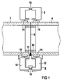
- two tubes 2 and 4 are pressed against one another on their opposite end faces while maintaining a pressing force.
- the tubes 2 and 4 are enclosed in the area of the annular joint 6 formed in this way by a guide ring 8, which is composed of two annular shells 10 and 12.
- These shells 10 and 12 form an annular housing in which a friction welding head 14 is guided, which rotates in the guide ring 8 in the circumferential direction of the tubes 2 and 4.
- the friction welding head 14 comprises a radially adjustable, rapidly rotating or rapidly radially moving friction mandrel 15, which is in the area the joint 6 penetrates into the tube wall while plasticizing the material of the tubes 2 and 4 and causes the tubes 2 and 4 to be welded in the circumferential direction of the tubes 2 and 4 when the friction welding head 14 is moved.
- the shells 10 and 12 of the guide ring 8 contain, distributed on their inner circumference, a large number of pressure stamps 16, which are issued radially inwards and position and fix the pipes 2 and 4 at the joint 6 to one another. These plungers 16 cause stiffening in order to absorb the high forces that occur during friction welding and to prevent the pipes 4 and 6 from being deformed. With the help of these pressure stamps, tubes 2 and 4 can also be pressed round if necessary.
- the shells 10 and 12 of the guide ring 8 are also, for example with hydraulic cylinders 18, axially adjustable to each other while maintaining a tensile force, so that the tubes 2 and 4 are pressed tightly together during friction welding.
- an insert ring 20 is additionally arranged on the inner circumference of the joint 6, with which the root formation is improved and the rigidity is increased in the case of thin pipes.
- the friction welding process begins with a radial feed movement of the friction mandrel 15, which plasticizes the pipe material at the joint 6 and penetrates into the wall of the two pipes 2 and 4.
- a movement of the friction welding head 14 in the circumferential direction can already be superimposed on this radial feed movement.
- the radial feed movement of the friction mandrel 15 preferably takes place until the tube wall is penetrated. After penetration of the tube wall and a subsequent complete rotation of the friction welding head 14 around the joint 6, the friction mandrel 15 is maintained the circumferential movement slowly pulled out of the tube wall, so that there is a wedge-shaped outlet. This ensures that the tubes 2 and 4 are securely and completely welded in the area of the weld root. The hole that is unavoidable during radial lifting is largely prevented in this way.
- welding filler of the same type during the run-out process. This takes place, for example, in the form of a wire which is brought to the weld from the outside or through the friction mandrel 15. In principle, it is also possible to close the end crater with a different melting and welding process.
- the guide ring 8 consists of two hinged half rings 82 and 84 in order to enable assembly on pipes 2, 4 which are already abutting.
- the conical or pin-shaped friction mandrels 15 shown in FIGS. 3 to 5 are particularly suitable for friction welding heads in which the frictional heat is generated by a rapid rotation of the friction mandrel 15.
- 6 to 8 show friction mandrels 15 in which the frictional heat is preferably caused by a rapid movement perpendicular to the surface of the workpiece, i.e. is generated radially to the pipe wall.
Landscapes
- Engineering & Computer Science (AREA)
- Mechanical Engineering (AREA)
- Pressure Welding/Diffusion-Bonding (AREA)
Applications Claiming Priority (2)
| Application Number | Priority Date | Filing Date | Title |
|---|---|---|---|
| DE19616285 | 1996-04-24 | ||
| DE19616285A DE19616285C1 (de) | 1996-04-24 | 1996-04-24 | Vorrichtung zum Fügen zweier Rohre |
Publications (3)
| Publication Number | Publication Date |
|---|---|
| EP0803314A2 true EP0803314A2 (fr) | 1997-10-29 |
| EP0803314A3 EP0803314A3 (fr) | 1998-02-11 |
| EP0803314B1 EP0803314B1 (fr) | 2001-11-14 |
Family
ID=7792255
Family Applications (1)
| Application Number | Title | Priority Date | Filing Date |
|---|---|---|---|
| EP97106017A Expired - Lifetime EP0803314B1 (fr) | 1996-04-24 | 1997-04-11 | Dispositif et procédé pour assembler deux tubes |
Country Status (2)
| Country | Link |
|---|---|
| EP (1) | EP0803314B1 (fr) |
| DE (2) | DE19616285C1 (fr) |
Cited By (4)
| Publication number | Priority date | Publication date | Assignee | Title |
|---|---|---|---|---|
| US7093745B2 (en) | 2003-01-14 | 2006-08-22 | Honda Motor Co., Ltd. | Method of and apparatus for friction stir welding |
| US7137545B2 (en) | 2003-01-14 | 2006-11-21 | Honda Motor Co., Ltd. | Method of friction stir welding |
| CN104907687A (zh) * | 2015-06-23 | 2015-09-16 | 中南大学 | 一种大口径薄壁圆筒对接焊接装配夹紧装置 |
| WO2016124168A1 (fr) * | 2015-02-06 | 2016-08-11 | Grenzebau Maschinenbau Gmbh | Dispositif et procédé pour le soudage par friction-malaxage mobile de deux structures tubulaires |
Families Citing this family (7)
| Publication number | Priority date | Publication date | Assignee | Title |
|---|---|---|---|---|
| US5697511A (en) * | 1996-09-27 | 1997-12-16 | Boeing North American, Inc. | Tank and method of fabrication |
| JP3333728B2 (ja) * | 1997-12-25 | 2002-10-15 | 東海ゴム工業株式会社 | ブッシュ装着用部材及びその製造方法 |
| JP2000117430A (ja) * | 1998-10-16 | 2000-04-25 | Tokai Rubber Ind Ltd | 突合せ継手構造 |
| DE10031416A1 (de) * | 2000-06-28 | 2002-01-10 | Hilti Ag | Reibschweissrohrverbindung und reibgeschweisstes Gesteinsbohrwerkzeug mit Bohrflüssigkeitskanal |
| US20080302539A1 (en) * | 2007-06-11 | 2008-12-11 | Frank's International, Inc. | Method and apparatus for lengthening a pipe string and installing a pipe string in a borehole |
| JP5700995B2 (ja) * | 2010-10-01 | 2015-04-15 | 川崎重工業株式会社 | 摩擦撹拌接合用治具、および摩擦撹拌接合の裏当て部材 |
| CN109702426B (zh) * | 2019-03-07 | 2020-12-15 | 江苏省特种设备安全监督检验研究院 | 一种采用辅助定位装置进行管道焊接的设备及工艺 |
Family Cites Families (5)
| Publication number | Priority date | Publication date | Assignee | Title |
|---|---|---|---|---|
| GB1505832A (en) * | 1974-12-02 | 1978-03-30 | Welding Inst | Friction welding methods and apparatus |
| DE3112770A1 (de) * | 1981-02-06 | 1983-05-11 | Hans Karl Dr. 7891 Küssaberg Leistritz | Rotationsverbund blechartiger formteile |
| SU1393566A1 (ru) * | 1985-10-08 | 1988-05-07 | Производственное Объединение "Вильнюсский Завод Топливной Аппаратуры Им.50-Летия Ссср" | Способ шовной сварки трением |
| GB9125978D0 (en) * | 1991-12-06 | 1992-02-05 | Welding Inst | Hot shear butt welding |
| NO942790D0 (no) * | 1994-03-28 | 1994-07-27 | Norsk Hydro As | Fremgangsmåte ved friksjonssveising og anordning for samme |
-
1996
- 1996-04-24 DE DE19616285A patent/DE19616285C1/de not_active Expired - Fee Related
-
1997
- 1997-04-11 EP EP97106017A patent/EP0803314B1/fr not_active Expired - Lifetime
- 1997-04-11 DE DE59705328T patent/DE59705328D1/de not_active Expired - Lifetime
Cited By (10)
| Publication number | Priority date | Publication date | Assignee | Title |
|---|---|---|---|---|
| US7093745B2 (en) | 2003-01-14 | 2006-08-22 | Honda Motor Co., Ltd. | Method of and apparatus for friction stir welding |
| US7137545B2 (en) | 2003-01-14 | 2006-11-21 | Honda Motor Co., Ltd. | Method of friction stir welding |
| US7441686B2 (en) | 2003-01-14 | 2008-10-28 | Honda Motor Co., Ltd. | Friction stir welding apparatus |
| WO2016124168A1 (fr) * | 2015-02-06 | 2016-08-11 | Grenzebau Maschinenbau Gmbh | Dispositif et procédé pour le soudage par friction-malaxage mobile de deux structures tubulaires |
| US20180021881A1 (en) * | 2015-02-06 | 2018-01-25 | Grenzebach Maschinenbau Gmbh | Apparatus and method for mobile friction stir welding of two tubular structures |
| AU2016214838B2 (en) * | 2015-02-06 | 2018-03-29 | Grenzebach Maschinenbau Gmbh | Apparatus and method for mobile friction stir welding of two tubular structures |
| EA034900B1 (ru) * | 2015-02-06 | 2020-04-03 | Гренцебах Машиненбау Гмбх | Устройство и способ для мобильной перемешивающей сварки трением двух трубчатых структур |
| US10730137B2 (en) | 2015-02-06 | 2020-08-04 | Grenzebach Maschinenbau Gmbh | Apparatus and method for mobile friction stir welding of two tubular structures |
| CN104907687A (zh) * | 2015-06-23 | 2015-09-16 | 中南大学 | 一种大口径薄壁圆筒对接焊接装配夹紧装置 |
| CN104907687B (zh) * | 2015-06-23 | 2017-10-17 | 中南大学 | 一种大口径薄壁圆筒对接焊接装配夹紧装置 |
Also Published As
| Publication number | Publication date |
|---|---|
| EP0803314A3 (fr) | 1998-02-11 |
| EP0803314B1 (fr) | 2001-11-14 |
| DE19616285C1 (de) | 1997-07-31 |
| DE59705328D1 (de) | 2001-12-20 |
Similar Documents
| Publication | Publication Date | Title |
|---|---|---|
| DE2553572C2 (fr) | ||
| EP1169156B1 (fr) | Procede et dispositif de soudage de deux pieces | |
| DE2929832C2 (de) | Verfahren und Vorrichtung zum Verbinden von Rohren durch Reibschweißen | |
| EP3253528B1 (fr) | Dispositif et procédé pour le soudage par friction-malaxage mobile de deux structures tubulaires | |
| DE2559532C3 (de) | Vorrichtung zum Ausrichten und Festlegen des Endes einer Rohrleitung und eines damit zu verschweißenden Rohrstückes | |
| EP0803314B1 (fr) | Dispositif et procédé pour assembler deux tubes | |
| DE2455934A1 (de) | Stuetz- und ausrichtanordnung, insbesondere fuer rohrverschweissungen | |
| EP3296055A1 (fr) | Dispositif et procédé de soudure par friction malaxage totalement pénétrante d'un joint circulaire sur des corps creux à symétrie de révolution | |
| WO1998004381A1 (fr) | Procede de liaison d'une piece plastifiable avec une autre piece | |
| DE2328080C3 (de) | Vorrichtung zum Zentrieren und Halten eines an ein Rohr anzuschweißenden glatten Flansches | |
| DE2633433C3 (de) | Vorrichtung zum zentrischen Spannen von ringförmigen Werkstücken | |
| DE2159591C3 (de) | Vorrichtung zum Stumpfschweißen von Rohren | |
| DE102008022713B4 (de) | Verfahren und Vorrichtung zum Aneinanderschweißen von unterschiedlich langen Rohrsegmenten | |
| EP0186904A1 (fr) | Procédé de fabrication de douilles de cartouches | |
| EP0689928A2 (fr) | Procédé et appareil pour le travail de tubes en matière plastique | |
| DE1627453C3 (de) | Reibstumpfschweißverfahren zum Verbinden von rohrförmigen Werkstückteilen | |
| DE19647707C2 (de) | Verfahren und Vorrichtung zum Verbinden von Bauteilen | |
| DE1958392B2 (de) | Verfahren und vorrichtung zur herstellung von stabelementen fuer raumfachwerke | |
| DE102020113012B4 (de) | Bearbeitungseinheit zum Laserauftragschweißen mit einer Zuführvorrichtung zum Zuführen eines Schweißzusatzelements | |
| DE2212013A1 (de) | Einrichtung zur automatischen Entfernung des Außenstauchgrates stumpfgeschweißter Metall- und Plastverbindungen | |
| DE102006013652B4 (de) | Bearbeitungswerkzeug sowie Verfahren zum Bearbeiten eines Werkstücks | |
| DE4138608A1 (de) | Heizelement-schweissverfahren fuer kunststoffelemente und vorrichtung zur durchfuehrung des verfahrens | |
| DE2264379A1 (de) | Flanschrohr | |
| EP0930479B1 (fr) | Méthode pour le raccordement de tuyaux et dispositif pour sa mise an oeuvre | |
| DE257136C (fr) |
Legal Events
| Date | Code | Title | Description |
|---|---|---|---|
| PUAI | Public reference made under article 153(3) epc to a published international application that has entered the european phase |
Free format text: ORIGINAL CODE: 0009012 |
|
| AK | Designated contracting states |
Kind code of ref document: A2 Designated state(s): DE FR GB SE |
|
| PUAL | Search report despatched |
Free format text: ORIGINAL CODE: 0009013 |
|
| AK | Designated contracting states |
Kind code of ref document: A3 Designated state(s): DE FR GB SE |
|
| 17P | Request for examination filed |
Effective date: 19980320 |
|
| RIC1 | Information provided on ipc code assigned before grant |
Free format text: 7B 23K 20/12 A |
|
| RTI1 | Title (correction) |
Free format text: DEVICE AND METHOD FOR JOINING TWO PIPES |
|
| GRAG | Despatch of communication of intention to grant |
Free format text: ORIGINAL CODE: EPIDOS AGRA |
|
| 17Q | First examination report despatched |
Effective date: 20000906 |
|
| GRAG | Despatch of communication of intention to grant |
Free format text: ORIGINAL CODE: EPIDOS AGRA |
|
| GRAG | Despatch of communication of intention to grant |
Free format text: ORIGINAL CODE: EPIDOS AGRA |
|
| GRAH | Despatch of communication of intention to grant a patent |
Free format text: ORIGINAL CODE: EPIDOS IGRA |
|
| GRAH | Despatch of communication of intention to grant a patent |
Free format text: ORIGINAL CODE: EPIDOS IGRA |
|
| RAP1 | Party data changed (applicant data changed or rights of an application transferred) |
Owner name: FRAMATOME ANP GMBH |
|
| GRAA | (expected) grant |
Free format text: ORIGINAL CODE: 0009210 |
|
| AK | Designated contracting states |
Kind code of ref document: B1 Designated state(s): DE FR GB SE |
|
| REF | Corresponds to: |
Ref document number: 59705328 Country of ref document: DE Date of ref document: 20011220 |
|
| REG | Reference to a national code |
Ref country code: GB Ref legal event code: IF02 |
|
| GBT | Gb: translation of ep patent filed (gb section 77(6)(a)/1977) |
Effective date: 20020130 |
|
| PLBE | No opposition filed within time limit |
Free format text: ORIGINAL CODE: 0009261 |
|
| STAA | Information on the status of an ep patent application or granted ep patent |
Free format text: STATUS: NO OPPOSITION FILED WITHIN TIME LIMIT |
|
| 26N | No opposition filed | ||
| REG | Reference to a national code |
Ref country code: FR Ref legal event code: CD |
|
| REG | Reference to a national code |
Ref country code: FR Ref legal event code: CA |
|
| PGFP | Annual fee paid to national office [announced via postgrant information from national office to epo] |
Ref country code: GB Payment date: 20130422 Year of fee payment: 17 Ref country code: DE Payment date: 20130423 Year of fee payment: 17 Ref country code: SE Payment date: 20130423 Year of fee payment: 17 |
|
| PGFP | Annual fee paid to national office [announced via postgrant information from national office to epo] |
Ref country code: FR Payment date: 20130523 Year of fee payment: 17 |
|
| REG | Reference to a national code |
Ref country code: DE Ref legal event code: R082 Ref document number: 59705328 Country of ref document: DE Representative=s name: MOERTEL, ALFRED, DIPL.-PHYS. DR.RER.NAT., DE |
|
| REG | Reference to a national code |
Ref country code: DE Ref legal event code: R082 Ref document number: 59705328 Country of ref document: DE Representative=s name: MEISSNER BOLTE & PARTNER GBR, DE Effective date: 20131112 Ref country code: DE Ref legal event code: R082 Ref document number: 59705328 Country of ref document: DE Representative=s name: MOERTEL, ALFRED, DIPL.-PHYS. DR.RER.NAT., DE Effective date: 20131112 Ref country code: DE Ref legal event code: R081 Ref document number: 59705328 Country of ref document: DE Owner name: AREVA GMBH, DE Free format text: FORMER OWNER: AREVA NP GMBH, 91052 ERLANGEN, DE Effective date: 20131112 |
|
| REG | Reference to a national code |
Ref country code: DE Ref legal event code: R082 Ref document number: 59705328 Country of ref document: DE Representative=s name: MEISSNER BOLTE & PARTNER GBR, DE |
|
| REG | Reference to a national code |
Ref country code: DE Ref legal event code: R119 Ref document number: 59705328 Country of ref document: DE |
|
| REG | Reference to a national code |
Ref country code: SE Ref legal event code: EUG |
|
| GBPC | Gb: european patent ceased through non-payment of renewal fee |
Effective date: 20140411 |
|
| REG | Reference to a national code |
Ref country code: FR Ref legal event code: ST Effective date: 20141231 |
|
| REG | Reference to a national code |
Ref country code: DE Ref legal event code: R119 Ref document number: 59705328 Country of ref document: DE Effective date: 20141101 |
|
| PG25 | Lapsed in a contracting state [announced via postgrant information from national office to epo] |
Ref country code: GB Free format text: LAPSE BECAUSE OF NON-PAYMENT OF DUE FEES Effective date: 20140411 Ref country code: SE Free format text: LAPSE BECAUSE OF NON-PAYMENT OF DUE FEES Effective date: 20140412 Ref country code: DE Free format text: LAPSE BECAUSE OF NON-PAYMENT OF DUE FEES Effective date: 20141101 |
|
| PG25 | Lapsed in a contracting state [announced via postgrant information from national office to epo] |
Ref country code: FR Free format text: LAPSE BECAUSE OF NON-PAYMENT OF DUE FEES Effective date: 20140430 |