EP0803314A2 - Device for joining two pipes - Google Patents
Device for joining two pipes Download PDFInfo
- Publication number
- EP0803314A2 EP0803314A2 EP97106017A EP97106017A EP0803314A2 EP 0803314 A2 EP0803314 A2 EP 0803314A2 EP 97106017 A EP97106017 A EP 97106017A EP 97106017 A EP97106017 A EP 97106017A EP 0803314 A2 EP0803314 A2 EP 0803314A2
- Authority
- EP
- European Patent Office
- Prior art keywords
- guide ring
- friction
- pipes
- friction welding
- joining
- Prior art date
- Legal status (The legal status is an assumption and is not a legal conclusion. Google has not performed a legal analysis and makes no representation as to the accuracy of the status listed.)
- Granted
Links
Images

Classifications
-
- B—PERFORMING OPERATIONS; TRANSPORTING
- B23—MACHINE TOOLS; METAL-WORKING NOT OTHERWISE PROVIDED FOR
- B23K—SOLDERING OR UNSOLDERING; WELDING; CLADDING OR PLATING BY SOLDERING OR WELDING; CUTTING BY APPLYING HEAT LOCALLY, e.g. FLAME CUTTING; WORKING BY LASER BEAM
- B23K20/00—Non-electric welding by applying impact or other pressure, with or without the application of heat, e.g. cladding or plating
- B23K20/12—Non-electric welding by applying impact or other pressure, with or without the application of heat, e.g. cladding or plating the heat being generated by friction; Friction welding
- B23K20/122—Non-electric welding by applying impact or other pressure, with or without the application of heat, e.g. cladding or plating the heat being generated by friction; Friction welding using a non-consumable tool, e.g. friction stir welding
- B23K20/1245—Non-electric welding by applying impact or other pressure, with or without the application of heat, e.g. cladding or plating the heat being generated by friction; Friction welding using a non-consumable tool, e.g. friction stir welding characterised by the apparatus
- B23K20/1255—Tools therefor, e.g. characterised by the shape of the probe
-
- B—PERFORMING OPERATIONS; TRANSPORTING
- B23—MACHINE TOOLS; METAL-WORKING NOT OTHERWISE PROVIDED FOR
- B23K—SOLDERING OR UNSOLDERING; WELDING; CLADDING OR PLATING BY SOLDERING OR WELDING; CUTTING BY APPLYING HEAT LOCALLY, e.g. FLAME CUTTING; WORKING BY LASER BEAM
- B23K20/00—Non-electric welding by applying impact or other pressure, with or without the application of heat, e.g. cladding or plating
- B23K20/12—Non-electric welding by applying impact or other pressure, with or without the application of heat, e.g. cladding or plating the heat being generated by friction; Friction welding
- B23K20/122—Non-electric welding by applying impact or other pressure, with or without the application of heat, e.g. cladding or plating the heat being generated by friction; Friction welding using a non-consumable tool, e.g. friction stir welding
- B23K20/1245—Non-electric welding by applying impact or other pressure, with or without the application of heat, e.g. cladding or plating the heat being generated by friction; Friction welding using a non-consumable tool, e.g. friction stir welding characterised by the apparatus
- B23K20/126—Workpiece support, i.e. backing or clamping
-
- B—PERFORMING OPERATIONS; TRANSPORTING
- B23—MACHINE TOOLS; METAL-WORKING NOT OTHERWISE PROVIDED FOR
- B23K—SOLDERING OR UNSOLDERING; WELDING; CLADDING OR PLATING BY SOLDERING OR WELDING; CUTTING BY APPLYING HEAT LOCALLY, e.g. FLAME CUTTING; WORKING BY LASER BEAM
- B23K2101/00—Articles made by soldering, welding or cutting
- B23K2101/04—Tubular or hollow articles
- B23K2101/06—Tubes
Definitions
- the invention relates to a device for joining two pipes by friction welding.
- a friction welding head which contains a rapidly moving, for example rotating, mandrel.
- This mandrel consists of a material that is harder and has a higher melting point than the material of the workpieces to be joined.
- the invention is based on the object of strengthening a device of the type mentioned in such a way that it is also suitable for joining two pipes.
- the device for joining two pipes by friction welding comprises a hinged guide ring for a friction welding head rotating in it, on which a radially adjustable friction mandrel is arranged.
- the guide ring is preferably formed from two interconnected annular shells which are axially adjustable with respect to one another while maintaining a tensile force.
- radially adjustable pressure rams are provided on the inner circumference of the guide ring for fixing the guide ring on both tubes.
- FIGS. 3 to 8 advantageous embodiments of a friction mandrel of the friction welding head are illustrated.
- two tubes 2 and 4 are pressed against one another on their opposite end faces while maintaining a pressing force.
- the tubes 2 and 4 are enclosed in the area of the annular joint 6 formed in this way by a guide ring 8, which is composed of two annular shells 10 and 12.
- These shells 10 and 12 form an annular housing in which a friction welding head 14 is guided, which rotates in the guide ring 8 in the circumferential direction of the tubes 2 and 4.
- the friction welding head 14 comprises a radially adjustable, rapidly rotating or rapidly radially moving friction mandrel 15, which is in the area the joint 6 penetrates into the tube wall while plasticizing the material of the tubes 2 and 4 and causes the tubes 2 and 4 to be welded in the circumferential direction of the tubes 2 and 4 when the friction welding head 14 is moved.
- the shells 10 and 12 of the guide ring 8 contain, distributed on their inner circumference, a large number of pressure stamps 16, which are issued radially inwards and position and fix the pipes 2 and 4 at the joint 6 to one another. These plungers 16 cause stiffening in order to absorb the high forces that occur during friction welding and to prevent the pipes 4 and 6 from being deformed. With the help of these pressure stamps, tubes 2 and 4 can also be pressed round if necessary.
- the shells 10 and 12 of the guide ring 8 are also, for example with hydraulic cylinders 18, axially adjustable to each other while maintaining a tensile force, so that the tubes 2 and 4 are pressed tightly together during friction welding.
- an insert ring 20 is additionally arranged on the inner circumference of the joint 6, with which the root formation is improved and the rigidity is increased in the case of thin pipes.
- the friction welding process begins with a radial feed movement of the friction mandrel 15, which plasticizes the pipe material at the joint 6 and penetrates into the wall of the two pipes 2 and 4.
- a movement of the friction welding head 14 in the circumferential direction can already be superimposed on this radial feed movement.
- the radial feed movement of the friction mandrel 15 preferably takes place until the tube wall is penetrated. After penetration of the tube wall and a subsequent complete rotation of the friction welding head 14 around the joint 6, the friction mandrel 15 is maintained the circumferential movement slowly pulled out of the tube wall, so that there is a wedge-shaped outlet. This ensures that the tubes 2 and 4 are securely and completely welded in the area of the weld root. The hole that is unavoidable during radial lifting is largely prevented in this way.
- welding filler of the same type during the run-out process. This takes place, for example, in the form of a wire which is brought to the weld from the outside or through the friction mandrel 15. In principle, it is also possible to close the end crater with a different melting and welding process.
- the guide ring 8 consists of two hinged half rings 82 and 84 in order to enable assembly on pipes 2, 4 which are already abutting.
- the conical or pin-shaped friction mandrels 15 shown in FIGS. 3 to 5 are particularly suitable for friction welding heads in which the frictional heat is generated by a rapid rotation of the friction mandrel 15.
- 6 to 8 show friction mandrels 15 in which the frictional heat is preferably caused by a rapid movement perpendicular to the surface of the workpiece, i.e. is generated radially to the pipe wall.
Landscapes
- Engineering & Computer Science (AREA)
- Mechanical Engineering (AREA)
- Pressure Welding/Diffusion-Bonding (AREA)
Abstract
Eine Vorrichtung zum Fügen zweier Rohre (2,4) durch Reibschweißen umfaßt einen aufklappbaren Führungsring (8) für einen in ihm umlaufenden Reibschweißkopf (14), der einen radial zustellbaren Reibdorn (15) enthält.
Description
Die Erfindung bezieht sich auf eine Vorrichtung zum Fügen zweier Rohre durch Reibschweißen.The invention relates to a device for joining two pipes by friction welding.
Zum Fügen zweier Werkstücke, beispielsweise Werkstücke aus Aluminium oder aus einer Aluminiumlegierung, ist es beispielsweise aus der WO 93/10935 bekannt, das zum Verschweißen an der Stoß- oder Fügestelle der Werkstücke notwendige Plastifizieren oder Aufschmelzen des Grundwerkstoffes durch einen mit Reibung erzeugten Wärmeeintrag herbeizuführen. Hierzu ist ein Reibschweißkopf vorgesehen, der einen sich schnell bewegenden, beispielsweise rotierenden, Reibdorn enthält. Dieser Reibdorn besteht aus einem Werkstoff, der härter und höher schmelzend ist als der Werkstoff der zu fügenden Werkstücke. Beim Fügen zweier plattenförmiger Werkstücke wird dieser Reibdorn seitlich im Bereich der Stoßstelle der Werkstücke an die Werkstücke angesetzt. Er dringt dann aufgrund des durch die schnelle Drehbewegung verursachte Plastifizieren des Werkstoffes bei gleichzeitiger Vorwärtsbewegung entlang der Füge- oder Stoßstelle in die Werkstücke ein und bewirkt so beim Abkühlen des plastifizierten Bereiches ein Verschweißen der beiden Werkstücke.For joining two workpieces, for example workpieces made of aluminum or an aluminum alloy, it is known, for example from WO 93/10935, to bring about the plasticizing or melting of the base material necessary for welding at the joint or joint of the workpieces by means of a heat input generated with friction. For this purpose, a friction welding head is provided, which contains a rapidly moving, for example rotating, mandrel. This mandrel consists of a material that is harder and has a higher melting point than the material of the workpieces to be joined. When joining two plate-shaped workpieces, this friction mandrel is attached to the workpieces laterally in the area of the joint of the workpieces. It then penetrates into the workpieces due to the plasticization of the material caused by the rapid rotary movement with simultaneous forward movement along the joint or joint, and thus causes the two workpieces to weld when the plasticized area cools.
Der Erfindung liegt nun die Aufgabe zugrunde, eine Vorrichtung der eingangs genannten Art derart zu ertüchtigen, daß sie auch zum Fügen zweier Rohre geeignet ist.The invention is based on the object of strengthening a device of the type mentioned in such a way that it is also suitable for joining two pipes.
Die genannte Aufgabe wird gelöst mit den Merkmalen des Patentanspruches 1.The stated object is achieved with the features of patent claim 1.
Die Vorrichtung zum Fügen zweier Rohre durch Reibschweißen umfaßt gemäß der Erfindung einen aufklappbaren Führungsring für einen in ihm umlaufenden Reibschweißkopf, an dem ein radial zustellbarer Reibdorn angeordnet ist.The device for joining two pipes by friction welding according to the invention comprises a hinged guide ring for a friction welding head rotating in it, on which a radially adjustable friction mandrel is arranged.
Vorzugsweise ist der Führungsring aus zwei miteinander verbundenen ringförmigen Schalen gebildet, die unter Aufrechterhaltung einer Zugkraft zueinander axial verstellbar sind.The guide ring is preferably formed from two interconnected annular shells which are axially adjustable with respect to one another while maintaining a tensile force.
In einer weiteren vorteilhaften Ausgestaltung sind am Innenumfang des Führungsringes radial verstellbare Druckstempel zum Fixieren des Führungsringes an beiden Rohren vorgesehen.In a further advantageous embodiment, radially adjustable pressure rams are provided on the inner circumference of the guide ring for fixing the guide ring on both tubes.
Zur weiteren Erläuterung der Erfindung wird auf die Ausführungsbeispiele der Zeichnung verwiesen, in deren
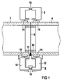
- FIG 1 eine Vorrichtung gemäß der Erfindung schematisch in einem Längsschnitt in einer Arbeitsposition veranschaulicht ist.
- FIG 2 zeigt die Vorrichtung während des Positionierens an den Rohren in einer axialen Draufsicht.
- 1 shows a device according to the invention is schematically illustrated in a longitudinal section in a working position.
- 2 shows the device during the positioning on the tubes in an axial top view.
In den Figuren 3 bis 8 sind vorteilhafte Ausführungsformen eines Reibdorns des Reibschweißkopfes veranschaulicht.In FIGS. 3 to 8, advantageous embodiments of a friction mandrel of the friction welding head are illustrated.
Gemäß FIG 1 sind zwei, beispielsweise aus Aluminium oder einer Aluminiumlegierung bestehende Rohre 2 und 4 an ihren einander gegenüberliegenden Stirnflächen unter Aufrechterhaltung einer Preßkraft aneinandergepreßt. Die Rohre 2 und 4 werden im Bereich der auf diese Weise gebildeten ringförmigen Stoßstelle 6 von einem Führungsring 8 umschlossen, der aus zwei ringförmigen Schalen 10 und 12 zusammengesetzt ist. Diese Schalen 10 und 12 bilden ein ringförmiges Gehäuse, in dem ein Reibschweißkopf 14 geführt ist, der im Führungsring 8 in Umfangsrichtung der Rohre 2 und 4 umläuft. Der Reibschweißkopf 14 umfaßt einen radial zustellbaren, schnell rotierenden oder sich schnell radial bewegenden Reibdorn 15, der im Bereich der Stoßstelle 6 unter Plastifizieren des Werkstoffes der Rohre 2 und 4 in die Rohrwand eindringt und beim Verfahren des Reibschweißkopfes 14 in Umfangsrichtung der Rohre 2 und 4 ein Verschweißen der Rohre 2 und 4 bewirkt.According to FIG. 1, two
Die Schalen 10 und 12 des Führungsringes 8 enthalten an ihrem Innenumfang verteilt eine Vielzahl von Druckstempeln 16, die radial nach innen ausgestellt werden und die Rohre 2 und 4 an der Stoßstelle 6 zueinander positionieren und fixieren. Diese Druckstempel 16 bewirken eine Versteifung, um die beim Reibschweißen auftretenden hohen Kräfte aufzunehmen und eine Deformation der Rohre 4 und 6 zu verhindern. Mit Hilfe dieser Druckstempel können die Rohre 2 und 4 erforderlichenfalls auch rundgedrückt werden.The
Die Schalen 10 und 12 des Führungsringes 8 sind außerdem, beispielsweise mit Hydraulikzylindern 18, axial zueinander unter Aufrechterhaltung einer Zugkraft verstellbar, so daß die Rohre 2 und 4 die während des Reibschweißens fest aneinandergepreßt werden.The
Im Ausführungsbeispiel der Figur ist am Innenumfang der Stoßstelle 6 zusätzlich ein Einlegering 20 angeordnet, mit dem die Wurzelausbildung verbessert und die Steifigkeit bei dünnen Rohren erhöht wird.In the exemplary embodiment of the figure, an
Der Reibschweißvorgang beginnt durch eine radiale Zustellbewegung des Reibdorns 15, der den Rohrwerkstoff an der Stoßstelle 6 plastifiziert und in die Wand der beiden Rohre 2 und 4 eindringt. Dieser radialen Zustellbewegung kann bereits eine Bewegung des Reibschweißkopfes 14 in Umfangsrichtung überlagert sein. Die radiale Zustellbewegung des Reibdorns 15 erfolgt vorzugsweise solange, bis die Rohrwand durchdrungen ist. Nach dem Durchdringen der Rohrwand und einem daran anschließenden kompletten Umlauf des Reibschweißkopfes 14 um die Stoßstelle 6 wird der Reibdorn 15 unter Aufrechterhaltung der Umlaufbewegung in Umfangsrichtung langsam aus der Rohrwand herausgezogen, so daß sich ein keilförmiger Auslauf ergibt. Dadurch ist sichergestellt, daß die Rohre 2 und 4 im Bereich der Schweißwurzel sicher und vollständig verschweißt sind. Das beim radialen Abheben unvermeidbar entstehende Loch wird auf diese Weise weitgehend verhindert.The friction welding process begins with a radial feed movement of the
Um beim Abheben eine Loch- oder Kraterbildung vollständig zu vermeiden, ist in einer bevorzugten Ausgestaltung vorgesehen, beim Auslaufvorgang zusätzlich artgleichen Schweißzusatz hinzuzufügen. Dies geschieht beispielsweise in Form eines Drahtes, der von außen oder durch den Reibdorn 15 hindurch an die Schweißstelle herangeführt wird. Prinzipiell ist es auch möglich, den Endkrater mit einem anderen Schmelz- und Schweißverfahren zu schließen.In order to completely avoid the formation of holes or craters when lifting off, in a preferred embodiment it is provided to additionally add welding filler of the same type during the run-out process. This takes place, for example, in the form of a wire which is brought to the weld from the outside or through the
In FIG 2 ist zu erkennen, daß der Führungsring 8 aus zwei aufklappbaren Halbringen 82 und 84 besteht, um eine Montage an bereits aneinander anstoßenden Rohren 2, 4 zu ermöglichen.In FIG 2 it can be seen that the
Die in FIG 3 bis 5 dargestellten kegeligen bzw. stiftförmigen Reibdorne 15 sind insbesondere für Reibschweißköpfe geeignet, bei denen die Reibungswärme durch eine schnelle Rotation des Reibdornes 15 entsteht.The conical or pin-
FIG 6 bis 8 zeigen Reibdorne 15, bei denen die Reibungswärme vorzugsweise durch eine schnelle Bewegung senkrecht zur Oberfläche des Werkstücks, d.h. radial zur Rohrwand erzeugt wird.6 to 8
Claims (3)
Applications Claiming Priority (2)
| Application Number | Priority Date | Filing Date | Title |
|---|---|---|---|
| DE19616285 | 1996-04-24 | ||
| DE19616285A DE19616285C1 (en) | 1996-04-24 | 1996-04-24 | Pipe jointing system using friction welding |
Publications (3)
| Publication Number | Publication Date |
|---|---|
| EP0803314A2 true EP0803314A2 (en) | 1997-10-29 |
| EP0803314A3 EP0803314A3 (en) | 1998-02-11 |
| EP0803314B1 EP0803314B1 (en) | 2001-11-14 |
Family
ID=7792255
Family Applications (1)
| Application Number | Title | Priority Date | Filing Date |
|---|---|---|---|
| EP97106017A Expired - Lifetime EP0803314B1 (en) | 1996-04-24 | 1997-04-11 | Device and method for joining two pipes |
Country Status (2)
| Country | Link |
|---|---|
| EP (1) | EP0803314B1 (en) |
| DE (2) | DE19616285C1 (en) |
Cited By (4)
| Publication number | Priority date | Publication date | Assignee | Title |
|---|---|---|---|---|
| US7093745B2 (en) | 2003-01-14 | 2006-08-22 | Honda Motor Co., Ltd. | Method of and apparatus for friction stir welding |
| US7137545B2 (en) | 2003-01-14 | 2006-11-21 | Honda Motor Co., Ltd. | Method of friction stir welding |
| CN104907687A (en) * | 2015-06-23 | 2015-09-16 | 中南大学 | Large-diameter thin walled cylinder butt welding assembly clamping device |
| WO2016124168A1 (en) * | 2015-02-06 | 2016-08-11 | Grenzebau Maschinenbau Gmbh | Apparatus and method for mobile friction stir welding of two tubular structures |
Families Citing this family (7)
| Publication number | Priority date | Publication date | Assignee | Title |
|---|---|---|---|---|
| US5697511A (en) * | 1996-09-27 | 1997-12-16 | Boeing North American, Inc. | Tank and method of fabrication |
| JP3333728B2 (en) * | 1997-12-25 | 2002-10-15 | 東海ゴム工業株式会社 | Bush mounting member and method of manufacturing the same |
| JP2000117430A (en) * | 1998-10-16 | 2000-04-25 | Tokai Rubber Ind Ltd | Butt joint structure |
| DE10031416A1 (en) * | 2000-06-28 | 2002-01-10 | Hilti Ag | Friction welding pipe connection and friction-welded rock drilling tool with drilling fluid channel |
| US20080302539A1 (en) * | 2007-06-11 | 2008-12-11 | Frank's International, Inc. | Method and apparatus for lengthening a pipe string and installing a pipe string in a borehole |
| JP5700995B2 (en) * | 2010-10-01 | 2015-04-15 | 川崎重工業株式会社 | Friction stir welding jig and backing member for friction stir welding |
| CN109702426B (en) * | 2019-03-07 | 2020-12-15 | 江苏省特种设备安全监督检验研究院 | A kind of equipment and process for pipeline welding using auxiliary positioning device |
Family Cites Families (5)
| Publication number | Priority date | Publication date | Assignee | Title |
|---|---|---|---|---|
| GB1505832A (en) * | 1974-12-02 | 1978-03-30 | Welding Inst | Friction welding methods and apparatus |
| DE3112770A1 (en) * | 1981-02-06 | 1983-05-11 | Hans Karl Dr. 7891 Küssaberg Leistritz | Rotary bond of sheet-like formed parts |
| SU1393566A1 (en) * | 1985-10-08 | 1988-05-07 | Производственное Объединение "Вильнюсский Завод Топливной Аппаратуры Им.50-Летия Ссср" | Method of seam friction welding |
| GB9125978D0 (en) * | 1991-12-06 | 1992-02-05 | Welding Inst | Hot shear butt welding |
| NO942790D0 (en) * | 1994-03-28 | 1994-07-27 | Norsk Hydro As | Method of friction welding and device for the same |
-
1996
- 1996-04-24 DE DE19616285A patent/DE19616285C1/en not_active Expired - Fee Related
-
1997
- 1997-04-11 EP EP97106017A patent/EP0803314B1/en not_active Expired - Lifetime
- 1997-04-11 DE DE59705328T patent/DE59705328D1/en not_active Expired - Lifetime
Cited By (10)
| Publication number | Priority date | Publication date | Assignee | Title |
|---|---|---|---|---|
| US7093745B2 (en) | 2003-01-14 | 2006-08-22 | Honda Motor Co., Ltd. | Method of and apparatus for friction stir welding |
| US7137545B2 (en) | 2003-01-14 | 2006-11-21 | Honda Motor Co., Ltd. | Method of friction stir welding |
| US7441686B2 (en) | 2003-01-14 | 2008-10-28 | Honda Motor Co., Ltd. | Friction stir welding apparatus |
| WO2016124168A1 (en) * | 2015-02-06 | 2016-08-11 | Grenzebau Maschinenbau Gmbh | Apparatus and method for mobile friction stir welding of two tubular structures |
| US20180021881A1 (en) * | 2015-02-06 | 2018-01-25 | Grenzebach Maschinenbau Gmbh | Apparatus and method for mobile friction stir welding of two tubular structures |
| AU2016214838B2 (en) * | 2015-02-06 | 2018-03-29 | Grenzebach Maschinenbau Gmbh | Apparatus and method for mobile friction stir welding of two tubular structures |
| EA034900B1 (en) * | 2015-02-06 | 2020-04-03 | Гренцебах Машиненбау Гмбх | Apparatus and method for mobile friction stir welding of two tubular structures |
| US10730137B2 (en) | 2015-02-06 | 2020-08-04 | Grenzebach Maschinenbau Gmbh | Apparatus and method for mobile friction stir welding of two tubular structures |
| CN104907687A (en) * | 2015-06-23 | 2015-09-16 | 中南大学 | Large-diameter thin walled cylinder butt welding assembly clamping device |
| CN104907687B (en) * | 2015-06-23 | 2017-10-17 | 中南大学 | A kind of large-caliber thin-walled cylinder butt welding assembling clamping device |
Also Published As
| Publication number | Publication date |
|---|---|
| EP0803314A3 (en) | 1998-02-11 |
| EP0803314B1 (en) | 2001-11-14 |
| DE19616285C1 (en) | 1997-07-31 |
| DE59705328D1 (en) | 2001-12-20 |
Similar Documents
| Publication | Publication Date | Title |
|---|---|---|
| DE2553572C2 (en) | ||
| EP1169156B1 (en) | Method and device for welding two work pieces | |
| DE2929832C2 (en) | Method and device for connecting pipes by friction welding | |
| EP3253528B1 (en) | Apparatus and method for mobile friction stir welding of two tubular structures | |
| DE2559532C3 (en) | Device for aligning and fixing the end of a pipeline and a pipe section to be welded to it | |
| EP0803314B1 (en) | Device and method for joining two pipes | |
| DE2455934A1 (en) | SUPPORT AND ALIGNMENT ARRANGEMENT, IN PARTICULAR FOR PIPE WELDING | |
| EP3296055A1 (en) | Device and method for through friction stir welding of a circular seam on rotation-symmetrical hollow bodies | |
| WO1998004381A1 (en) | Process for joining a workpiece which can be plasticised to another workpiece | |
| DE2328080C3 (en) | Device for centering and holding a smooth flange to be welded to a pipe | |
| DE2633433C3 (en) | Device for the central clamping of ring-shaped workpieces | |
| DE2159591C3 (en) | Device for butt welding pipes | |
| DE102008022713B4 (en) | Method and apparatus for welding together pipe segments of different length | |
| EP0186904A1 (en) | Method for making cartridge ammunition cases | |
| EP0689928A2 (en) | Process and apparatus for working plastic tubes | |
| DE1627453C3 (en) | Friction butt welding process for joining tubular workpiece parts | |
| DE19647707C2 (en) | Method and device for connecting components | |
| DE1958392B2 (en) | METHOD AND DEVICE FOR MANUFACTURING BAR ELEMENTS FOR FRAMEWORKS | |
| DE102020113012B4 (en) | Processing unit for laser deposition welding with a feed device for feeding an additional welding element | |
| DE2212013A1 (en) | Device for the automatic removal of the external upsetting ridge of butt-welded metal and plastic connections | |
| DE102006013652B4 (en) | Machining tool and method for machining a workpiece | |
| DE4138608A1 (en) | Plastics tube and component welding - involves using heated bush round tube at component joint with inner tube support | |
| DE2264379A1 (en) | FLANGE PIPE | |
| EP0930479B1 (en) | Method for the connection of pipes and device for carrying out the same | |
| DE257136C (en) |
Legal Events
| Date | Code | Title | Description |
|---|---|---|---|
| PUAI | Public reference made under article 153(3) epc to a published international application that has entered the european phase |
Free format text: ORIGINAL CODE: 0009012 |
|
| AK | Designated contracting states |
Kind code of ref document: A2 Designated state(s): DE FR GB SE |
|
| PUAL | Search report despatched |
Free format text: ORIGINAL CODE: 0009013 |
|
| AK | Designated contracting states |
Kind code of ref document: A3 Designated state(s): DE FR GB SE |
|
| 17P | Request for examination filed |
Effective date: 19980320 |
|
| RIC1 | Information provided on ipc code assigned before grant |
Free format text: 7B 23K 20/12 A |
|
| RTI1 | Title (correction) |
Free format text: DEVICE AND METHOD FOR JOINING TWO PIPES |
|
| GRAG | Despatch of communication of intention to grant |
Free format text: ORIGINAL CODE: EPIDOS AGRA |
|
| 17Q | First examination report despatched |
Effective date: 20000906 |
|
| GRAG | Despatch of communication of intention to grant |
Free format text: ORIGINAL CODE: EPIDOS AGRA |
|
| GRAG | Despatch of communication of intention to grant |
Free format text: ORIGINAL CODE: EPIDOS AGRA |
|
| GRAH | Despatch of communication of intention to grant a patent |
Free format text: ORIGINAL CODE: EPIDOS IGRA |
|
| GRAH | Despatch of communication of intention to grant a patent |
Free format text: ORIGINAL CODE: EPIDOS IGRA |
|
| RAP1 | Party data changed (applicant data changed or rights of an application transferred) |
Owner name: FRAMATOME ANP GMBH |
|
| GRAA | (expected) grant |
Free format text: ORIGINAL CODE: 0009210 |
|
| AK | Designated contracting states |
Kind code of ref document: B1 Designated state(s): DE FR GB SE |
|
| REF | Corresponds to: |
Ref document number: 59705328 Country of ref document: DE Date of ref document: 20011220 |
|
| REG | Reference to a national code |
Ref country code: GB Ref legal event code: IF02 |
|
| GBT | Gb: translation of ep patent filed (gb section 77(6)(a)/1977) |
Effective date: 20020130 |
|
| PLBE | No opposition filed within time limit |
Free format text: ORIGINAL CODE: 0009261 |
|
| STAA | Information on the status of an ep patent application or granted ep patent |
Free format text: STATUS: NO OPPOSITION FILED WITHIN TIME LIMIT |
|
| 26N | No opposition filed | ||
| REG | Reference to a national code |
Ref country code: FR Ref legal event code: CD |
|
| REG | Reference to a national code |
Ref country code: FR Ref legal event code: CA |
|
| PGFP | Annual fee paid to national office [announced via postgrant information from national office to epo] |
Ref country code: GB Payment date: 20130422 Year of fee payment: 17 Ref country code: DE Payment date: 20130423 Year of fee payment: 17 Ref country code: SE Payment date: 20130423 Year of fee payment: 17 |
|
| PGFP | Annual fee paid to national office [announced via postgrant information from national office to epo] |
Ref country code: FR Payment date: 20130523 Year of fee payment: 17 |
|
| REG | Reference to a national code |
Ref country code: DE Ref legal event code: R082 Ref document number: 59705328 Country of ref document: DE Representative=s name: MOERTEL, ALFRED, DIPL.-PHYS. DR.RER.NAT., DE |
|
| REG | Reference to a national code |
Ref country code: DE Ref legal event code: R082 Ref document number: 59705328 Country of ref document: DE Representative=s name: MEISSNER BOLTE & PARTNER GBR, DE Effective date: 20131112 Ref country code: DE Ref legal event code: R082 Ref document number: 59705328 Country of ref document: DE Representative=s name: MOERTEL, ALFRED, DIPL.-PHYS. DR.RER.NAT., DE Effective date: 20131112 Ref country code: DE Ref legal event code: R081 Ref document number: 59705328 Country of ref document: DE Owner name: AREVA GMBH, DE Free format text: FORMER OWNER: AREVA NP GMBH, 91052 ERLANGEN, DE Effective date: 20131112 |
|
| REG | Reference to a national code |
Ref country code: DE Ref legal event code: R082 Ref document number: 59705328 Country of ref document: DE Representative=s name: MEISSNER BOLTE & PARTNER GBR, DE |
|
| REG | Reference to a national code |
Ref country code: DE Ref legal event code: R119 Ref document number: 59705328 Country of ref document: DE |
|
| REG | Reference to a national code |
Ref country code: SE Ref legal event code: EUG |
|
| GBPC | Gb: european patent ceased through non-payment of renewal fee |
Effective date: 20140411 |
|
| REG | Reference to a national code |
Ref country code: FR Ref legal event code: ST Effective date: 20141231 |
|
| REG | Reference to a national code |
Ref country code: DE Ref legal event code: R119 Ref document number: 59705328 Country of ref document: DE Effective date: 20141101 |
|
| PG25 | Lapsed in a contracting state [announced via postgrant information from national office to epo] |
Ref country code: GB Free format text: LAPSE BECAUSE OF NON-PAYMENT OF DUE FEES Effective date: 20140411 Ref country code: SE Free format text: LAPSE BECAUSE OF NON-PAYMENT OF DUE FEES Effective date: 20140412 Ref country code: DE Free format text: LAPSE BECAUSE OF NON-PAYMENT OF DUE FEES Effective date: 20141101 |
|
| PG25 | Lapsed in a contracting state [announced via postgrant information from national office to epo] |
Ref country code: FR Free format text: LAPSE BECAUSE OF NON-PAYMENT OF DUE FEES Effective date: 20140430 |