EP0803312A2 - Procédé et appareil pour le soudage à la molette - Google Patents
Procédé et appareil pour le soudage à la molette Download PDFInfo
- Publication number
- EP0803312A2 EP0803312A2 EP97104990A EP97104990A EP0803312A2 EP 0803312 A2 EP0803312 A2 EP 0803312A2 EP 97104990 A EP97104990 A EP 97104990A EP 97104990 A EP97104990 A EP 97104990A EP 0803312 A2 EP0803312 A2 EP 0803312A2
- Authority
- EP
- European Patent Office
- Prior art keywords
- molded part
- welding
- sheet
- seam
- welded
- Prior art date
- Legal status (The legal status is an assumption and is not a legal conclusion. Google has not performed a legal analysis and makes no representation as to the accuracy of the status listed.)
- Granted
Links
- 238000003466 welding Methods 0.000 title claims abstract description 51
- 238000000034 method Methods 0.000 title claims description 16
- NJPPVKZQTLUDBO-UHFFFAOYSA-N novaluron Chemical compound C1=C(Cl)C(OC(F)(F)C(OC(F)(F)F)F)=CC=C1NC(=O)NC(=O)C1=C(F)C=CC=C1F NJPPVKZQTLUDBO-UHFFFAOYSA-N 0.000 claims abstract description 4
- 238000000465 moulding Methods 0.000 claims 1
- 239000002184 metal Substances 0.000 abstract description 11
- 238000003780 insertion Methods 0.000 description 3
- 230000037431 insertion Effects 0.000 description 3
- 239000000463 material Substances 0.000 description 3
- 230000006978 adaptation Effects 0.000 description 1
- 210000000245 forearm Anatomy 0.000 description 1
- 230000001788 irregular Effects 0.000 description 1
- 238000009423 ventilation Methods 0.000 description 1
Images

Classifications
-
- B—PERFORMING OPERATIONS; TRANSPORTING
- B23—MACHINE TOOLS; METAL-WORKING NOT OTHERWISE PROVIDED FOR
- B23K—SOLDERING OR UNSOLDERING; WELDING; CLADDING OR PLATING BY SOLDERING OR WELDING; CUTTING BY APPLYING HEAT LOCALLY, e.g. FLAME CUTTING; WORKING BY LASER BEAM
- B23K11/00—Resistance welding; Severing by resistance heating
- B23K11/06—Resistance welding; Severing by resistance heating using roller electrodes
- B23K11/061—Resistance welding; Severing by resistance heating using roller electrodes for welding rectilinear seams
- B23K11/062—Resistance welding; Severing by resistance heating using roller electrodes for welding rectilinear seams for welding longitudinal seams of tubes
- B23K11/063—Lap welding
Definitions
- the invention relates to a welding process in which a body which is essentially open on both ends is formed from a flat sheet metal and welded along its edges. For example, in the case of roller seam welding, the body is shaped so as to overlap and welding rolls are fed with its overlap area.
- the invention further relates to an apparatus for performing the method.
- roller seam welding is then carried out by advancing the sheet through the guide tools with welding rollers acting on the overlap and generally using wire electrodes.
- sheets which have recesses or consist of materials of different thicknesses or are cut so that the end face of the rounded body is not perpendicular to the longitudinal axis or the direction of the weld seam, problems arise with these known roller guide tools, since clear guidance and centering of the Workpiece no longer guaranteed is. Such welds are therefore still not carried out by conventional welding machines.
- the invention is therefore based on the object of providing a method for welding sheet metal, in particular sheet metal jacket, by means of which any sheet metal blank shape and also sheet metal with recesses or differences in material thickness or hardness can be welded.
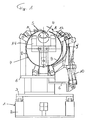
- FIG. 1 shows a view of a welding machine seen in the longitudinal direction, ie in the direction of the seam to be welded.
- the welding machine 1 has a machine frame 2 on which a movable carriage 3 is arranged.
- the forearm 4 of the welding machine and the Z-rail 5 can also be seen.
- the welding rollers are arranged in a known manner at the front above the plane of the drawing, so that a frame located in the Z-rail with its overlap from the inner one and the outer welding roll can be welded.
- a corresponding structure of the roller seam welding machine is known and is not shown in detail here.
- the carriage 3 mentioned is movably arranged on the machine frame 2 and carries the molded part 7 on a pedestal 6.
- the molded part 7 consists of two halves 8 and 9.
- the internal shape of the molded part is approximately adapted to the body to be produced.
- the molded part 7 has a fixed part 8 and a portion 9 which can be pivoted away to open the molded part and which is designated 9 in the closed position and 9 'in the open position.
- the opening and closing of the molded part 7, or the opening and closing of the section 9, can be effected with a hydraulic cylinder 10, which is attached at one end to the platform 6 and at the other end to the part 9.
- the procedure for welding a body is as follows: a sheet is introduced directly from the round apparatus into the opened molded part and is located above the molded part 7.
- the sheet rolled by the forming rollers of the round apparatus is, as indicated by the arrow A, introduced obliquely from above into the opened molded part.
- the sheet bears against the inner wall of the molded part 7.
- the rounded plate assumes the desired position, which corresponds to the inner shape of the molded part 7, and the longitudinal edges of the plate reach the grooves of the Z-rail 5 in a known manner.
- the plate directly from the Round apparatus from obliquely above into the molded part 7 can also be a manual insertion of a previously rounded sheet into the molded part.
- the insertion takes place from the front, ie in the direction of view on the drawing.
- the body is arranged with its longitudinal edges in the Z-rail and is held by the molded part over its circumference.
- Stops 11 and 12 are now preferably provided in the front region of the molded part and can be moved into the molded part after the sheet has been introduced. During the insertion of the sheet, the stops are pulled out of the molded part in order not to interfere with the introduction of the sheet, especially if the sheet is irregularly shaped.
- the position of the stops 11 and 12 can be adjusted in the longitudinal direction in order to adapt the stops to the respective cut shape of the sheet.
- the stops are moved into the molded part and a further movable stop 14 moves from behind against the inserted sheet metal and pushes it against the front stops 11 and 12.
- the shaped sheet metal is centered in the longitudinal direction of the molded part 7 and held regardless of whether it has irregular outer dimensions and whether inner areas are cut out.
- the workpiece to be welded is now arranged in the molded part 8 and fixed there. Now the entire molded part 7 is moved forward by means of the slide 3, so that the overlapping longitudinal edges of the workpiece to be welded get between the welding rollers.
- the further movement of the workpiece with the molded part 7 can be carried out by the welding rollers, ie the slide 3 would then be freely movable and is only moved forward by the driving force exerted by the welding rollers.
- the molded part is preferably driven with the slide at the set welding speed during the welding process. This drive of the slide and thus of the molded part or the workpiece relieves the welding rollers and improves the seam quality of the welding seam, since slippage between the welding rollers and the workpiece is excluded.
- the Stops 11 and 12 are moved out of the molded part again and the stop 14 is moved backwards and the molded part is opened so that the welded workpiece can be removed.
- the molded part then moves back to its rear end position and is ready to be loaded with a new rounded plate.
- a sufficiently long sled can also be loaded with several molded parts at the same time.
- FIG. 2 shows a side view of the device from FIG. 1, the same reference numbers denoting the same parts.
- the rear stop is shown in two positions 14 and 14 '.
- the molded part enables the clamping, centering and welding of cylindrical or differently shaped frames, whereby with differently shaped frames the molded part with its inner shape must be adapted to the desired workpiece shape in such a way that the edges to be welded reach the definitive welding position and remain fixed there. In any case, in contrast to conventional calibration rolls, the molded part enables rounding and welding of any shape.
- the abovementioned stops which are preferably arranged in the molded part and which can be actuated pneumatically prevent the workpiece from being offset in the molded part and permit precise longitudinal centering.
- the rear stop 14 which preferably has a very long stroke, results in a simple adaptation of the molded part to different frame heights.
- the molded part also has the advantage that the restrictive cutting tolerances required in the conventional guide tools can be significantly increased, since the molded part is not sensitive to such tolerances, in contrast to the known roller guide tools.
Landscapes
- Engineering & Computer Science (AREA)
- Mechanical Engineering (AREA)
- Butt Welding And Welding Of Specific Article (AREA)
- Bending Of Plates, Rods, And Pipes (AREA)
- Lining Or Joining Of Plastics Or The Like (AREA)
Applications Claiming Priority (3)
| Application Number | Priority Date | Filing Date | Title |
|---|---|---|---|
| CH101396 | 1996-04-22 | ||
| CH01013/96A CH692910A5 (de) | 1996-04-22 | 1996-04-22 | Verfahren und Vorrichtung zum Schweissen, insbesondere zum Rollnathschweissen. |
| CH1013/96 | 1996-04-22 |
Publications (3)
| Publication Number | Publication Date |
|---|---|
| EP0803312A2 true EP0803312A2 (fr) | 1997-10-29 |
| EP0803312A3 EP0803312A3 (fr) | 1998-02-04 |
| EP0803312B1 EP0803312B1 (fr) | 2002-07-31 |
Family
ID=4200421
Family Applications (1)
| Application Number | Title | Priority Date | Filing Date |
|---|---|---|---|
| EP97104990A Expired - Lifetime EP0803312B1 (fr) | 1996-04-22 | 1997-03-25 | Procédé et appareil pour le soudage à la molette |
Country Status (6)
| Country | Link |
|---|---|
| US (2) | US6098869A (fr) |
| EP (1) | EP0803312B1 (fr) |
| JP (1) | JPH1052759A (fr) |
| CH (1) | CH692910A5 (fr) |
| DE (1) | DE59707832D1 (fr) |
| DK (1) | DK0803312T3 (fr) |
Cited By (2)
| Publication number | Priority date | Publication date | Assignee | Title |
|---|---|---|---|---|
| CN102441749A (zh) * | 2010-09-30 | 2012-05-09 | 江苏江桥机械制造有限公司 | 一种放丝式自动变径滚焊机的同步机构 |
| CN116532905A (zh) * | 2023-07-07 | 2023-08-04 | 西安航宇动力控制科技有限公司 | 一种圆柱薄壁耐高压壳体焊接装置 |
Families Citing this family (10)
| Publication number | Priority date | Publication date | Assignee | Title |
|---|---|---|---|---|
| DE10049283A1 (de) * | 2000-10-05 | 2002-04-11 | Hueck Folien Gmbh & Co Kg | Verfahren und Vorrichtung zur Herstellung einer zylindrischen Prägeform |
| DE102004046687B3 (de) * | 2004-09-24 | 2006-06-01 | Thyssenkrupp Steel Ag | Verfahren und Vorrichtung zur Herstellung eines längsnahtgeschweißten Hohlprofils |
| DE102005006578B3 (de) * | 2005-02-11 | 2006-03-16 | Benteler Automobiltechnik Gmbh | Verfahren zur Herstellung von Rohren |
| WO2007134459A1 (fr) * | 2006-05-23 | 2007-11-29 | Innovequity Inc. | Poutrelles formant une machine de construction et procédé associé |
| US10052718B2 (en) * | 2011-02-10 | 2018-08-21 | Honda Motor Co., Ltd. | Cylindrical workpiece cutting apparatus |
| JP7027122B2 (ja) * | 2017-10-27 | 2022-03-01 | シロキ工業株式会社 | 車両用ドアサッシュのシーム溶接方法 |
| CN108672566B (zh) * | 2018-06-28 | 2024-04-02 | 浙江正鼎汽车零部件有限公司 | 用于卷圆的模具 |
| CN110039164B (zh) * | 2019-04-23 | 2021-06-08 | 江西华士科技股份有限公司 | 一种油桶自动缝焊机 |
| CN111922138B (zh) * | 2020-07-29 | 2022-08-12 | 佛山市金常旺不锈钢有限公司 | 一种卷板成型工艺 |
| CN116000628B (zh) * | 2022-11-29 | 2023-07-21 | 滁州恒昌机械装备制造有限公司 | 一种钣金件的焊接设备 |
Family Cites Families (18)
| Publication number | Priority date | Publication date | Assignee | Title |
|---|---|---|---|---|
| US1628928A (en) * | 1923-05-02 | 1927-05-17 | American Can Co | Method and apparatus for making can bodies |
| US3627964A (en) * | 1963-07-26 | 1971-12-14 | Amf Inc | Lapped welding of metal edge portions |
| GB1201202A (en) * | 1967-05-16 | 1970-08-05 | Walter Somers Materials Handli | Improvements in or relating to welding of tubular blanks |
| US3615968A (en) * | 1967-11-24 | 1971-10-26 | Grace W R & Co | Metal-metal bonding |
| US3585337A (en) * | 1969-05-26 | 1971-06-15 | Amf Inc | Forge welding by hi-frequency heating and metal deposition |
| US3834010A (en) * | 1972-09-19 | 1974-09-10 | R Wolfe | Method for forming welded seam can bodies |
| US4070887A (en) * | 1976-11-01 | 1978-01-31 | Tube Machinery Corporation | Roll former for tube mill |
| EP0023753B1 (fr) * | 1979-08-06 | 1985-08-14 | Toyo Seikan Kaisha Limited | Procédé et appareil pour la construction de boîtes métalliques soudées |
| JPS5756173A (en) * | 1980-09-19 | 1982-04-03 | Daiwa Can Co Ltd | Electric resistance seaming and welding method of lateral joint of hollow cylindrical body |
| JPS57106480A (en) * | 1980-12-24 | 1982-07-02 | Fuji Kogyosho:Kk | Method and device for fully automatic resistance seam welding of thin walled can body |
| CH674327A5 (fr) * | 1984-12-19 | 1990-05-31 | Elpatronic Ag | |
| US5011064A (en) * | 1985-10-19 | 1991-04-30 | Heinrich Fuss | Method of manufacturing a double-walled tube |
| JPS6316887A (ja) * | 1986-07-07 | 1988-01-23 | Toyo Seikan Kaisha Ltd | 溶接缶胴体 |
| US4805795A (en) * | 1986-12-27 | 1989-02-21 | Toyo Seikan Kaisha Ltd. | Butt-welded cans and process for manufacturing the same |
| CH671893A5 (fr) * | 1987-05-05 | 1989-10-13 | Elpatronic Ag | |
| US4842186A (en) * | 1987-10-30 | 1989-06-27 | The Babock & Wilcox Company | Method and apparatus for building a workpiece by deposit welding |
| US5344062A (en) * | 1993-06-24 | 1994-09-06 | The Idod Trust | Method of forming seamed metal tube |
| EP0761365B1 (fr) * | 1995-09-04 | 2000-10-18 | Elpatronic Ag | Procédé et appareil pour le soudage à la molette de récipients |
-
1996
- 1996-04-22 CH CH01013/96A patent/CH692910A5/de not_active IP Right Cessation
-
1997
- 1997-03-25 DK DK97104990T patent/DK0803312T3/da active
- 1997-03-25 EP EP97104990A patent/EP0803312B1/fr not_active Expired - Lifetime
- 1997-03-25 DE DE59707832T patent/DE59707832D1/de not_active Expired - Fee Related
- 1997-04-09 US US08/838,670 patent/US6098869A/en not_active Expired - Fee Related
- 1997-04-22 JP JP9104355A patent/JPH1052759A/ja active Pending
-
1999
- 1999-09-27 US US09/406,670 patent/US6288355B1/en not_active Expired - Fee Related
Cited By (4)
| Publication number | Priority date | Publication date | Assignee | Title |
|---|---|---|---|---|
| CN102441749A (zh) * | 2010-09-30 | 2012-05-09 | 江苏江桥机械制造有限公司 | 一种放丝式自动变径滚焊机的同步机构 |
| CN102441749B (zh) * | 2010-09-30 | 2015-05-20 | 江苏江桥机械制造有限公司 | 一种放丝式自动变径滚焊机的同步机构 |
| CN116532905A (zh) * | 2023-07-07 | 2023-08-04 | 西安航宇动力控制科技有限公司 | 一种圆柱薄壁耐高压壳体焊接装置 |
| CN116532905B (zh) * | 2023-07-07 | 2023-09-01 | 西安航宇动力控制科技有限公司 | 一种圆柱薄壁耐高压壳体焊接装置 |
Also Published As
| Publication number | Publication date |
|---|---|
| EP0803312A3 (fr) | 1998-02-04 |
| US6288355B1 (en) | 2001-09-11 |
| JPH1052759A (ja) | 1998-02-24 |
| DK0803312T3 (da) | 2002-10-07 |
| US6098869A (en) | 2000-08-08 |
| CH692910A5 (de) | 2002-12-13 |
| EP0803312B1 (fr) | 2002-07-31 |
| DE59707832D1 (de) | 2002-09-05 |
Similar Documents
| Publication | Publication Date | Title |
|---|---|---|
| DE3722290C1 (de) | Kalibrierwerkzeug fuer eine Maschine zum Laengsnahtschweissen gerundeter Dosenzargen | |
| EP0803312B1 (fr) | Procédé et appareil pour le soudage à la molette | |
| EP1128926B1 (fr) | Procede et dispositif pour le positionnement d'aretes, en particulier lors du soudage d'un tube | |
| DE2328080C3 (de) | Vorrichtung zum Zentrieren und Halten eines an ein Rohr anzuschweißenden glatten Flansches | |
| DE1953409A1 (de) | Verfahren und Vorrichtung zum Herstellen eines Ballons | |
| EP1128925B1 (fr) | Procede et dispositif pour souder des tubes | |
| DE1949272A1 (de) | Verfahren zum Verjuengen des Endes eines Werkstueckes und Vorrichtung zur Durchfuehrung des Verfahrens | |
| DE2620190B2 (de) | Elektrische Widerstands-Stumpfschweißmaschine | |
| EP0743135B1 (fr) | Procédé de jonction de deux pièces | |
| DE2642583A1 (de) | Schweissmaschine zum verbinden von bandstahlabschnitten oder -rollen | |
| DE3323190A1 (de) | Vorrichtung zum herstellen von papierbehaeltern | |
| DE69129077T2 (de) | Verfahren und vorrichtung zum schneiden von rohren, in welchem die rohre mittels einer rotierenden festhaltplatte in schneidposition gebracht werden | |
| DE2331121C3 (de) | Schneidmaschine zum Aufschlitzen von langgestreckten, rohrförmigen Werkstücken in Axialrichtung | |
| CH673604A5 (fr) | ||
| DE4332008C2 (de) | Schneidvorrichtung für dünnwandige Rohre | |
| EP1060036A1 (fr) | Procede et dispositif pour la fabrication de tubes | |
| EP0027106A1 (fr) | Dispositif pour amener automatiquement du matériau en tiges à une machine à cintrer des brides d'armature de béton | |
| DE4028372C1 (fr) | ||
| DE3706550C2 (de) | Verfahren zum Auswerfen des Abfallstückes des äußeren Endes einer Hülse aus einer Hülsenschneidmaschine sowie Vorrichtung zur Durchführung des Verfahrens | |
| EP1632307B1 (fr) | Méthode et appareil pour soudage par recouvrement de tôles tubulaires | |
| DE4404541C1 (de) | Verfahren zum Herstellen von Faßringen | |
| DE102006026136B3 (de) | Vorrichtung zum Formen von Hohlprofilen | |
| EP0042450A1 (fr) | Procédé pour la fabrication d'enveloppes de pots d'échappement à joint longitudinal plié et dispositif pour la réalisation de ce procédé | |
| DE2253928C3 (de) | Verfahren und Vorrichtung zum Herstellen eines mit Lötgut versehenen Werkstückes | |
| DE2140934C3 (de) | Anlage zum Verbinden mehrerer Rohre zu längeren Abschnitten |
Legal Events
| Date | Code | Title | Description |
|---|---|---|---|
| PUAI | Public reference made under article 153(3) epc to a published international application that has entered the european phase |
Free format text: ORIGINAL CODE: 0009012 |
|
| AK | Designated contracting states |
Kind code of ref document: A2 Designated state(s): CH DE DK GB LI NL SE |
|
| PUAL | Search report despatched |
Free format text: ORIGINAL CODE: 0009013 |
|
| AK | Designated contracting states |
Kind code of ref document: A3 Designated state(s): CH DE DK GB LI NL SE |
|
| 17P | Request for examination filed |
Effective date: 19980804 |
|
| RAP3 | Party data changed (applicant data changed or rights of an application transferred) |
Owner name: ELPATRONIC AG |
|
| 17Q | First examination report despatched |
Effective date: 19991215 |
|
| GRAG | Despatch of communication of intention to grant |
Free format text: ORIGINAL CODE: EPIDOS AGRA |
|
| GRAG | Despatch of communication of intention to grant |
Free format text: ORIGINAL CODE: EPIDOS AGRA |
|
| GRAH | Despatch of communication of intention to grant a patent |
Free format text: ORIGINAL CODE: EPIDOS IGRA |
|
| GRAH | Despatch of communication of intention to grant a patent |
Free format text: ORIGINAL CODE: EPIDOS IGRA |
|
| GRAA | (expected) grant |
Free format text: ORIGINAL CODE: 0009210 |
|
| AK | Designated contracting states |
Kind code of ref document: B1 Designated state(s): CH DE DK GB LI NL SE |
|
| REG | Reference to a national code |
Ref country code: GB Ref legal event code: FG4D Free format text: NOT ENGLISH Ref country code: CH Ref legal event code: EP |
|
| REF | Corresponds to: |
Ref document number: 59707832 Country of ref document: DE Date of ref document: 20020905 |
|
| REG | Reference to a national code |
Ref country code: DK Ref legal event code: T3 |
|
| GBT | Gb: translation of ep patent filed (gb section 77(6)(a)/1977) |
Effective date: 20021111 |
|
| PLBE | No opposition filed within time limit |
Free format text: ORIGINAL CODE: 0009261 |
|
| STAA | Information on the status of an ep patent application or granted ep patent |
Free format text: STATUS: NO OPPOSITION FILED WITHIN TIME LIMIT |
|
| 26N | No opposition filed |
Effective date: 20030506 |
|
| PGFP | Annual fee paid to national office [announced via postgrant information from national office to epo] |
Ref country code: NL Payment date: 20060314 Year of fee payment: 10 Ref country code: DE Payment date: 20060314 Year of fee payment: 10 |
|
| PGFP | Annual fee paid to national office [announced via postgrant information from national office to epo] |
Ref country code: DK Payment date: 20060315 Year of fee payment: 10 Ref country code: CH Payment date: 20060315 Year of fee payment: 10 |
|
| PG25 | Lapsed in a contracting state [announced via postgrant information from national office to epo] |
Ref country code: SE Free format text: LAPSE BECAUSE OF NON-PAYMENT OF DUE FEES Effective date: 20070326 |
|
| REG | Reference to a national code |
Ref country code: DK Ref legal event code: EBP |
|
| REG | Reference to a national code |
Ref country code: CH Ref legal event code: PL |
|
| EUG | Se: european patent has lapsed | ||
| GBPC | Gb: european patent ceased through non-payment of renewal fee |
Effective date: 20070325 |
|
| NLV4 | Nl: lapsed or anulled due to non-payment of the annual fee |
Effective date: 20071001 |
|
| PG25 | Lapsed in a contracting state [announced via postgrant information from national office to epo] |
Ref country code: NL Free format text: LAPSE BECAUSE OF NON-PAYMENT OF DUE FEES Effective date: 20071001 Ref country code: DE Free format text: LAPSE BECAUSE OF NON-PAYMENT OF DUE FEES Effective date: 20071002 |
|
| PGFP | Annual fee paid to national office [announced via postgrant information from national office to epo] |
Ref country code: SE Payment date: 20060314 Year of fee payment: 10 |
|
| PG25 | Lapsed in a contracting state [announced via postgrant information from national office to epo] |
Ref country code: CH Free format text: LAPSE BECAUSE OF NON-PAYMENT OF DUE FEES Effective date: 20070331 Ref country code: LI Free format text: LAPSE BECAUSE OF NON-PAYMENT OF DUE FEES Effective date: 20070331 |
|
| PG25 | Lapsed in a contracting state [announced via postgrant information from national office to epo] |
Ref country code: GB Free format text: LAPSE BECAUSE OF NON-PAYMENT OF DUE FEES Effective date: 20070325 Ref country code: DK Free format text: LAPSE BECAUSE OF NON-PAYMENT OF DUE FEES Effective date: 20070402 |
|
| PGFP | Annual fee paid to national office [announced via postgrant information from national office to epo] |
Ref country code: GB Payment date: 20060322 Year of fee payment: 10 |