EP0803280A2 - Vorrichtung zur Gasauswechslung - Google Patents
Vorrichtung zur Gasauswechslung Download PDFInfo
- Publication number
- EP0803280A2 EP0803280A2 EP96116231A EP96116231A EP0803280A2 EP 0803280 A2 EP0803280 A2 EP 0803280A2 EP 96116231 A EP96116231 A EP 96116231A EP 96116231 A EP96116231 A EP 96116231A EP 0803280 A2 EP0803280 A2 EP 0803280A2
- Authority
- EP
- European Patent Office
- Prior art keywords
- housing
- hollow fiber
- gas
- gas exchange
- inlet
- Prior art date
- Legal status (The legal status is an assumption and is not a legal conclusion. Google has not performed a legal analysis and makes no representation as to the accuracy of the status listed.)
- Withdrawn
Links
Images

Classifications
-
- B—PERFORMING OPERATIONS; TRANSPORTING
- B01—PHYSICAL OR CHEMICAL PROCESSES OR APPARATUS IN GENERAL
- B01D—SEPARATION
- B01D63/00—Apparatus in general for separation processes using semi-permeable membranes
- B01D63/02—Hollow fibre modules
-
- B—PERFORMING OPERATIONS; TRANSPORTING
- B01—PHYSICAL OR CHEMICAL PROCESSES OR APPARATUS IN GENERAL
- B01D—SEPARATION
- B01D53/00—Separation of gases or vapours; Recovering vapours of volatile solvents from gases; Chemical or biological purification of waste gases, e.g. engine exhaust gases, smoke, fumes, flue gases, aerosols
- B01D53/22—Separation of gases or vapours; Recovering vapours of volatile solvents from gases; Chemical or biological purification of waste gases, e.g. engine exhaust gases, smoke, fumes, flue gases, aerosols by diffusion
-
- B—PERFORMING OPERATIONS; TRANSPORTING
- B01—PHYSICAL OR CHEMICAL PROCESSES OR APPARATUS IN GENERAL
- B01D—SEPARATION
- B01D63/00—Apparatus in general for separation processes using semi-permeable membranes
- B01D63/02—Hollow fibre modules
- B01D63/027—Twinned or braided type modules
-
- B—PERFORMING OPERATIONS; TRANSPORTING
- B01—PHYSICAL OR CHEMICAL PROCESSES OR APPARATUS IN GENERAL
- B01D—SEPARATION
- B01D69/00—Semi-permeable membranes for separation processes or apparatus characterised by their form, structure or properties; Manufacturing processes specially adapted therefor
- B01D69/08—Hollow fibre membranes
-
- A—HUMAN NECESSITIES
- A61—MEDICAL OR VETERINARY SCIENCE; HYGIENE
- A61M—DEVICES FOR INTRODUCING MEDIA INTO, OR ONTO, THE BODY; DEVICES FOR TRANSDUCING BODY MEDIA OR FOR TAKING MEDIA FROM THE BODY; DEVICES FOR PRODUCING OR ENDING SLEEP OR STUPOR
- A61M1/00—Suction or pumping devices for medical purposes; Devices for carrying-off, for treatment of, or for carrying-over, body-liquids; Drainage systems
- A61M1/14—Dialysis systems; Artificial kidneys; Blood oxygenators ; Reciprocating systems for treatment of body fluids, e.g. single needle systems for hemofiltration or pheresis
- A61M1/16—Dialysis systems; Artificial kidneys; Blood oxygenators ; Reciprocating systems for treatment of body fluids, e.g. single needle systems for hemofiltration or pheresis with membranes
- A61M1/1698—Blood oxygenators with or without heat-exchangers
-
- B—PERFORMING OPERATIONS; TRANSPORTING
- B01—PHYSICAL OR CHEMICAL PROCESSES OR APPARATUS IN GENERAL
- B01D—SEPARATION
- B01D2313/00—Details relating to membrane modules or apparatus
- B01D2313/20—Specific housing
- B01D2313/201—Closed housing, vessels or containers
-
- B—PERFORMING OPERATIONS; TRANSPORTING
- B01—PHYSICAL OR CHEMICAL PROCESSES OR APPARATUS IN GENERAL
- B01D—SEPARATION
- B01D2313/00—Details relating to membrane modules or apparatus
- B01D2313/20—Specific housing
- B01D2313/205—Specific housing characterised by the shape
Definitions
- the present invention relates to a gas exchange apparatus employing the silicone membrane hollow fiber for use as an artificial lung itself by being connected to the external blood circulation circuit, an artificial "Gill” as a liquid-to-gas phase gas exchanger, and further an oxygenator and disoxidizer for liquid and gas.
- a membrane-type artificial lung disclosed in Japanese Patent Publication No. 3-60508 (1991), in which gas exchange operation is performed through a porous gas exchange membrane having a plurality of minute or fine openings formed therethrough and serving as gas flow passages, wherein a kind of fine particles are maintained in the fine openings to reduce the sectional area, and, in addition, an anti-coagulant for blood is retained in the fine particles themselves or between these particles.
- Such a retention function of the agent contributes to prevent leakage of components of blood, such as water or , during a long-term circulation, and also to prevent production of thrombus on the surface of gas exchange membrane, thereby the out-body circulation being enabled with a small amount of heparin supplement.
- Another gas exchanger is disclosed using a "silicone membrane hollow fiber having a wall thickness of 50 to 150 micron", such as an anti-thrombus fiber type artificial lung disclosed in Japanese laid-open patent publication No. 63-97172, in which a hydrophilic monomer is graft-polymerized on the surface of a hollow fiber membrane, which is received in a housing, wherein blood is allowed to flow outside the hollow fiber membrane, and an oxygen-containing gas is allowed to flow inside the membrane.
- this artificial lung since blood is allowed to come in contact with the outer surface of the membrane, the surface of which being anti-thrombus treated, the production of thrombus is advantageously hardly caused.
- the gas exchange rate was not satisfactory in either of the conventional gas exchanger, since fine particles are confined in fine openings using "porous hollow fiber” for preventing sealum leakage in the first example, and "silicone membrane hollow fiber" having an increased wall thickness as 50 to 150 microns is used in the second embodiment. Therefore, there have been problems, when the exchange rate is increased, the dimension of the apparatus, that is, of the artificial lung increases, resulting in an increased quantity of blood, namely the priming volume, which is filled in the apparatus. In contrast, the reduced priming volume, although providing a small size, the quantity of gas exchange is accordingly decreased, and, therefore, the gas exchange rate is lowered.
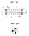
- a gas exchange apparatus for use as an artificial lung is fundamentally comprised of a hollow fiber module M 1 formed by bundling a plurality of silicone thin-walled hollow fibers wound in the form of a twilled pattern so as to form an internal perfusion passage and an external perfusion passage; a housing H 1 for enclosing the hollow fiber module; a first inlet A and a first outlet B formed on the housing H 1 for gas or liquid for communication with the internal perfusion passage; and a second inlet C and a second outlet D formed on the housing for gas or liquid for communication with the external perfusion passage.
- the hollow fiber such as disclosed in prior patent application No.7-159899 (1995) filed by the same inventors may be used, which has not exceeding 400 microns in external diameter, not exceeding 50 microns in membrane thickness, and 100 % elongation load strength of not lower than 5 g, composed of a silicone membrane composition including the following (a) to (e):
- the above hollow fiber 1 is prepared including a step of extruding the above silicone rubber component with heating and vulcanizing using a vulcanizing chamber to be elongated, wherein the ratio of the sectional area S 1 of the tube being extruded between a die and a nipple relative to the sectional area S 2 of the tube after being extruded, that is, the ratio S 1 by S 2 being a value between 1:0.5 to 1:0.01.
- a hollow fiber module M 1 is fabricated in that, as shown in FIG.1, the silicone membrane fiber 1 is wound around a core 2 in the form of twill figure with the angle of 30 to 160°, with the hollow fibers at both ends being sealed with silicone resin to each other, and thereafter the sealed portions are cut out in the radial direction to allow the ends of the hollow fiber 1 to be freed. Therefore, the module M 1 , is in the form that hollow fibers 1 each having a predetermined length are bundled in the twill form around the core 2 and the cross section thereof is circular.
- the silicone rubber hollow fiber 1 may be, in the range of not exceeding 400 microns in diameter and not exceeding 50 microns in wall thickness, of the same internal and external diameters, or a plurality of kinds thereof having the same internal diameter but having each external diameter different from each other may be used.
- the bundling density of the hollow fiber may be either uniform or ununiform.
- the volume ratio that is, the volume occupied by the hollow fibers within the housing, may be preferably 10 to 70%.
- the housing H 1 is formed as a cylinder in section with the ends thereof being closed, wherein a first inlet A and a first outlet B are formed on both end walls of housing H 1 , respectively.
- a second inlet C and outlet D are formed on the side wall of housing H1 with a predetermined distance therebetween in the opposite radial direction to each other.
- Housing H 1 may have also an elliptic section, whereby the module M 1 may have an elliptic section,
- Hollow fiber module M 1 is received within the housing H 1 , the ends being sealed with silicone resin, and the core 2 is closed at both ens also with silicone resin.
- the internal and external circulation passages for the module M 1 are formed within the housing H 1 .
- the internal passage being formed inside the hollow fibers is in communication with the first inlet A and second outlet B, while the external passage being formed outside the silicone wall is in communication with the second inlet and outlet passages C and D.
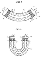
- Gas exchangers shown in FIGS.2 to 9 are those modified from that shown in FIG.1. These are also included in the scope of the invention. Those shown in FIGS.2 and 3 are different from that in FIG.1 in the shape of the housings H 2 and H 3 , respectively. Namely, these housings are modified in a curved form and a U-shaped form, respectively.
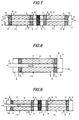
- housings H 4 , H 5 and H 6 in FIGS.4, 5 and 6 are modified form FIGS. 1, 2, and 3 so as to be gradually slimmed from one end to the other end along the axial direction of the housing.
- the hollow fiber modules M 2 , M 3 , M 5 and M 6 are received into the housings H 2 , H 3 , H 5 and H 6 , respectively, after removing the cores from each housing.
- the bundling density of the minor diameter is relatively larger than the major.
- a gas exchanger shown in FIG.7 is of the form of two exchangers in FIG.1 combined in series together with a partition 6 interposed therebetween, having the first inlets A and E, first outlets B and F, second inlets C and G, and second outlets D and H.
- a gas exchanger shown in FIG.8 is provided with a core 4 of the hollow fiber module M 7 , the core 4 being extended out of the housing H 7 to form a second outlet D in communication with the external perfusion passage; from such second outlet D and through an opening 5 formed in the core 4, a liquid or gas is vented to an external perfusion passage and exhausted from the second outlet D.
- the gas exchanger in FIG.9 is formed so that the left device of the apparatus shown in FIG.7 is replaced by the gas exchanger of FIG.8.
- FIGS.2 to 9 are not essentially different form that in FIG.1.
- any elongation or excessive wound stress or the like of the hollow fiber is prevented even a considerable tension is applied, because of using a silicone membrane fiber having a thin wall thickness but having sufficient toughness.
- the hollow fiber may be formed by an arbitrary density, thereby the volume ratio of the silicone membrane hollow fiber relative to the internal volume of the housing being able to be arbitrary set. At this time, by using the different size of hollow fibers, the same effect can be achieved as changing the bundling density.
- the filling density of silicone membrane hollow fibers in the hollow fiber module, the crossing angle of the hollow fibers, as well as the volume ratio between the occupied area of fibers and the internal volume of the housing (the hollow fiber filling density), may be also arbitrarily selected.
- the configuration of the housing may be arbitrarily selected.
- the flow of liquid within the internal and external perfusion passages, more particularly the disturbance flow of the gas or liquid are adequately controlled, thereby the gas exchange rate being increased to allow the apparatus to be small-sized and the priming volume to be reduced.
- the gas exchanger shown in FIG.1 as an artificial lung has been prepared through the following procedures:
- each of silicone membrane hollow fiber having an external diameter of 400 microns, wall thickness of 50 microns, and tensile weight (M 100 ) of 5 gram, was prepared.
- a number of hollow fibers above were twill wound and bundled to form the modules M 1 of the types I and II, each of which was enclosed within each housing H 1 of types I and II to form an internal perfusion passage and an external perfusion passage in each housing H 1, for communicating with first inlet A and outlet B, and for communicating with second external inlet C and outlet B, respectively.
- a hollow fiber module of type I is a hollow fiber module of type I:
- a hollow fiber module of type II is a hollow fiber module of type II:
- a housing of type I is a housing of type I:
- a housing of type II is a housing of type II:
- a cylindrically formed housing having both ends thereof closed, formed of polycarbonate, having an internal diameter of 55mm, and a length of 200mm, provided with a first inlet A, a first outlet B, a second inlet C, and a second outlet D.
- Each of modules M 1 of types I and II above includes silicone membrane hollow fibers 1 having an external diameter of 8mm and wound in twilled form with a crossing angle of 120°, wherein the fibers were sealed at both ends with silicone resin, thereafter the sealed portions were cut away along the radial direction.
- the volume ratio of silicone membrane hollow fibers relative to the sectional area of the housing H 1 was 35%.
- the effective membrane area of the housing H 1 was 1.6 m 2 in the case using the type I, and 2 m 2 in the case of type II.
- the breakdown strength of the membrane of silicone hollow fiber 1 was from about 950 to 2100 g/mm 2 , which was twice that of the conventional silicone membrane hollow fiber.
- the internal and external perfusion passages were formed by sealing the housing H 1 with the second portion 3 of module M 1 of types I and II with silicone resin, and closing the both ends with also silicone resin.
- an internal and an external perfusion passages for fiber module M 1 are formed in the housing H 1 .
- the first inlet A together with the first outlet B provides the entrance/exit for internal perfusion passage, while a second inlet C and a second outlet D provides the entrance/exit for external perfusion passage.
- three pieces of artificial lungs of type I each comprising a hollow fiber module of type I together with a housing of type I
- three pieces of artificial lungs of type II each comprising a hollow fiber module of type II together with a housing of type II, were prepared, each of which was evaluated in vitro as follows.
- Evaluation in vitro was performed using fresh cow blood in such a manner that preparing 20 liters of the blood added with ACD-A solution as the anti-coagulant at the collecting time, which was converted to the standard venous blood by a commercially available artificial lung to be subjected to evaluation in vitro.
- the blood was fed to the external perfusion passage, and oxygen (by gas state) was supplied through the internal perfusion passage.
- the blood circuit was formed by a tube having an inner diameter of 3/8 inch connected to second inlet C and outlet D, and a boat for collecting blood and measuring the pressure was provided adjacent the inlet C and outlet D.
- the blood circulation was carried out by a roller pump attached to the tube.
- the rate of blood flow was 1, 2 or 3 liter/min
- oxygen flow in the artificial lung of type I was by the ratio of oxygen flow Q versus blood flow V (V/Q) being 1 and 2, while the ratio was 1 in the case of the lung of type II.
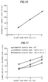
- oxygen (O 2 ) transfer rate in either artificial lung of types I and II, the oxygen saturation rate by each flow rate of blood at the side of second outlet D was as high as 99 to 100%.
- the transfer rate of carbon dioxide was in the range of from 158 to 164ml/min in the case using the lung of type II at the same blood flow rate.
- the pressure loss was increased in proportion with the blood flow rate in either of the lungs of types I and II, the value of which being 196.64 mmHg at a blood flow rate of 3 liter/min.
- the blood filling volume (priming volume) was 150 ml(milli liter) by the lung of type I, and 240 ml by the lung of type II.
- the change of the blood filling volume caused by additional pressure of 500 mmHg was measured: as a result, the volume change rate was, at either of the gas side and blood side, in the order of 0.2 to 0.3 ml, which corresponds to 0.1 % or so of the blood filling rate.
- the invention provides a small-sized gas exchange apparatus of high performance having an increased gas exchange rate and a minimized priming volume.
Landscapes
- Chemical & Material Sciences (AREA)
- Chemical Kinetics & Catalysis (AREA)
- Engineering & Computer Science (AREA)
- Analytical Chemistry (AREA)
- General Chemical & Material Sciences (AREA)
- Oil, Petroleum & Natural Gas (AREA)
- External Artificial Organs (AREA)
- Separation Using Semi-Permeable Membranes (AREA)
Applications Claiming Priority (2)
| Application Number | Priority Date | Filing Date | Title |
|---|---|---|---|
| JP107524/96 | 1996-04-26 | ||
| JP10752496A JP3803421B2 (ja) | 1996-04-26 | 1996-04-26 | 気体交換装置 |
Publications (2)
| Publication Number | Publication Date |
|---|---|
| EP0803280A2 true EP0803280A2 (de) | 1997-10-29 |
| EP0803280A3 EP0803280A3 (de) | 1998-04-29 |
Family
ID=14461385
Family Applications (1)
| Application Number | Title | Priority Date | Filing Date |
|---|---|---|---|
| EP96116231A Withdrawn EP0803280A3 (de) | 1996-04-26 | 1996-10-10 | Vorrichtung zur Gasauswechslung |
Country Status (3)
| Country | Link |
|---|---|
| US (1) | US5855201A (de) |
| EP (1) | EP0803280A3 (de) |
| JP (1) | JP3803421B2 (de) |
Cited By (2)
| Publication number | Priority date | Publication date | Assignee | Title |
|---|---|---|---|---|
| US6855122B1 (en) | 1999-02-10 | 2005-02-15 | Tomio Ohta | Bloodless treating device |
| US10076620B2 (en) | 2012-12-22 | 2018-09-18 | Dmf Medical Incorporated | Anesthetic circuit having a hollow fiber membrane |
Families Citing this family (15)
| Publication number | Priority date | Publication date | Assignee | Title |
|---|---|---|---|---|
| WO2000047252A1 (en) * | 1999-02-10 | 2000-08-17 | Nikkiso Co., Ltd. | Cancer therapeutic agent supply device |
| CN1433328A (zh) | 1999-12-03 | 2003-07-30 | 神经原治疗公司 | 人造脑脊液的闭合再循环的方法和设备 |
| SE519630C2 (sv) * | 2001-08-30 | 2003-03-18 | Gambro Lundia Ab | Kateter och metod för tillverkning därav |
| JP4666248B2 (ja) * | 2004-05-27 | 2011-04-06 | 東洋紡績株式会社 | 高強度高透水性中空糸膜型血液浄化器 |
| KR100721054B1 (ko) * | 2004-11-23 | 2007-05-25 | 주식회사 뉴하트바이오 | 혈액정화 및/또는 혈액산화용 필터모듈, 그를 이용한혈액정화 및 혈액산화 방법 그리고 그를 포함하는혈액정화 장치 |
| JP4468485B2 (ja) * | 2007-12-04 | 2010-05-26 | パナソニック株式会社 | 燃料電池システム |
| US8545754B2 (en) | 2009-04-23 | 2013-10-01 | Medtronic, Inc. | Radial design oxygenator with heat exchanger |
| DE102011108786A1 (de) | 2011-07-29 | 2013-01-31 | Fresenius Medical Care Deutschland Gmbh | Verfahren zum Ermitteln wenigstens eines Parameters eines extrakorporalen Blutkreislaufs sowie Vorrichtungen |
| EP2777801B1 (de) * | 2013-03-15 | 2019-08-28 | Maquet Cardiopulmonary AG | Vorrichtung zur CO2-Eliminierung von Patientenblut |
| DE102013209832A1 (de) * | 2013-05-27 | 2014-11-27 | Siemens Aktiengesellschaft | Vorrichtung und Verfahren zur Kontrastmittelgabe bei einer Magnetresonanztomographie |
| JP2015139954A (ja) * | 2014-01-29 | 2015-08-03 | 富士システムズ株式会社 | シリコーン部材の接着方法 |
| JP6555489B2 (ja) * | 2017-04-17 | 2019-08-07 | シーズテック株式会社 | ガス交換装置 |
| US10758844B2 (en) * | 2017-07-25 | 2020-09-01 | Hamilton Sundstrand Corporation | Fluid degassing devices having selected profiles |
| ES3063470T3 (en) | 2017-08-15 | 2026-04-16 | Univ Maryland | Dual chamber gas exchanger |
| DE102018008459A1 (de) * | 2018-10-29 | 2020-04-30 | Enmodes Gmbh | Vorrichtung für den Stoffaustausch zwischen Blut- und wenigstens einem Gas/Gasgemisch |
Family Cites Families (21)
| Publication number | Priority date | Publication date | Assignee | Title |
|---|---|---|---|---|
| US3422008A (en) * | 1963-10-24 | 1969-01-14 | Dow Chemical Co | Wound hollow fiber permeability apparatus and process of making the same |
| FR2102707A5 (en) * | 1970-08-14 | 1972-04-07 | Rhodiaceta | Organo polysiloxane hollow filaments - for artificial kidneys and lungs and cardio-vascular surgery |
| US3969240A (en) * | 1975-02-03 | 1976-07-13 | The United States Of America As Represented By The Department Of Health, Education And Welfare | Polysiloxane membrane lung |
| US3994988A (en) * | 1975-03-10 | 1976-11-30 | Baxter Laboratories, Inc. | Thermoplastic copolymers of polysiloxane polycarbonate and polyester constituents |
| US4336138A (en) * | 1975-07-26 | 1982-06-22 | Toyobo Co., Ltd. | Permeation separation apparatus |
| US4342723A (en) * | 1978-11-24 | 1982-08-03 | Shin-Etsu Polymer Co., Ltd. | Gas-exchange sheet members |
| US4444662A (en) * | 1979-10-22 | 1984-04-24 | Applied Membrane Technology, Inc. | Microporous laminate |
| JPS59218161A (ja) * | 1983-05-27 | 1984-12-08 | テルモ株式会社 | 中空繊維型人工肺およびその製造方法 |
| US4719142A (en) * | 1983-07-07 | 1988-01-12 | General Electric Company | Transparent membrane structures |
| ZA8680B (en) * | 1985-01-08 | 1987-08-26 | Mcneilab Inc | Mass transfer device having a microporous,spirally wound hollow fiber membrane |
| US4876066A (en) * | 1986-07-14 | 1989-10-24 | Baxter International Inc. | Integrated membrane oxygenator, heat exchanger and reservoir |
| EP0394221B1 (de) * | 1987-07-28 | 1993-10-27 | Minntech Corporation | Blutoxygenerator vom äusseren perfusionstyp |
| US5188801A (en) * | 1988-06-07 | 1993-02-23 | Cortek S.P.A. | Device for the treatment of blood |
| DE68922908T2 (de) * | 1989-01-13 | 1995-11-02 | Minntech Corp., Minneapolis, Minn. | Keilform für eine sauerstoffvorrichtung. |
| US5578267A (en) * | 1992-05-11 | 1996-11-26 | Minntech Corporation | Cylindrical blood heater/oxygenator |
| US5270004A (en) * | 1989-10-01 | 1993-12-14 | Minntech Corporation | Cylindrical blood heater/oxygenator |
| JPH0549693A (ja) * | 1991-08-27 | 1993-03-02 | Shin Etsu Polymer Co Ltd | 発泡シリコーンゴム製中空糸及びそれを用いた中空糸型人工肺 |
| US5472613A (en) * | 1993-04-19 | 1995-12-05 | Envirosep Inc. | Removing volatile and non-volatile organic in a thick film equilibrium process and device |
| US5376334A (en) * | 1993-05-19 | 1994-12-27 | Avecor Cardiovascular Inc. | Mass transfer device having a hollow fiber bundle |
| JP3712012B2 (ja) * | 1995-06-02 | 2005-11-02 | 信越化学工業株式会社 | シリコーンゴムチューブの成型方法及び薄膜シリコーンゴムシート |
| JPH0959517A (ja) * | 1995-06-12 | 1997-03-04 | Fuji Syst Kk | シリコーンゴム組成物並びに同組成物を使用した中空糸及び同中空糸の製造方法 |
-
1996
- 1996-04-26 JP JP10752496A patent/JP3803421B2/ja not_active Expired - Lifetime
- 1996-09-27 US US08/720,052 patent/US5855201A/en not_active Expired - Lifetime
- 1996-10-10 EP EP96116231A patent/EP0803280A3/de not_active Withdrawn
Cited By (3)
| Publication number | Priority date | Publication date | Assignee | Title |
|---|---|---|---|---|
| US6855122B1 (en) | 1999-02-10 | 2005-02-15 | Tomio Ohta | Bloodless treating device |
| US10076620B2 (en) | 2012-12-22 | 2018-09-18 | Dmf Medical Incorporated | Anesthetic circuit having a hollow fiber membrane |
| US10960160B2 (en) | 2012-12-22 | 2021-03-30 | Dmf Medical Incorporated | Anesthetic circuit having a hollow fiber membrane |
Also Published As
| Publication number | Publication date |
|---|---|
| US5855201A (en) | 1999-01-05 |
| EP0803280A3 (de) | 1998-04-29 |
| JPH09290020A (ja) | 1997-11-11 |
| JP3803421B2 (ja) | 2006-08-02 |
Similar Documents
| Publication | Publication Date | Title |
|---|---|---|
| US5855201A (en) | Gas exchange apparatus | |
| CA1158510A (en) | Hollow fiber-type artificial lung having enclosed heat exchanger | |
| EP0176651B1 (de) | Wärmeaustauscher mit Sauerstoffanreicherung für Blut | |
| EP0853951B1 (de) | Perkutaner, aufblasbarer Oxygenator mit transversalen Hohlfasern | |
| US4659549A (en) | Blood oxygenator using a hollow fiber membrane | |
| CA1216207A (en) | Hollow fiber-type artificial lung | |
| EP0164025B1 (de) | Oxygenator der Hohlfaser-Membranart und Verfahren zur Herstellung desselben | |
| US4948560A (en) | Oxygenator | |
| EP0803259B1 (de) | Gasaustauschvorrichtung unter Verwendung von verbesserten Hohlfasern aus Silikonkautschuk | |
| EP0600035A1 (de) | Vorrichtung und methode zur extrakorporalen sauerstoffanreicherung | |
| JPS624994B2 (de) | ||
| JPS6241742B2 (de) | ||
| US5263982A (en) | Hollow fiber membrane type artificial lung | |
| JPH0439862B2 (de) | ||
| JPH0321189B2 (de) | ||
| EP0157941B1 (de) | Blutoxygenator mit einer Hohlfasermembran | |
| JPS61247465A (ja) | 中空糸膜型人工肺 | |
| JP3152691B2 (ja) | 多孔質中空糸膜、人工肺および体外循環回路 | |
| JP2515828Y2 (ja) | 中空糸型人工肺 | |
| JPH0732801B2 (ja) | 熱交換器一体型人工肺 | |
| JPS61115574A (ja) | 中空糸膜型人工肺 | |
| JPS63189160A (ja) | ガス交換効率の優れた中空糸型人工肺 | |
| JPS61115572A (ja) | 中空糸膜型人工肺 | |
| JPS60225572A (ja) | 中空糸膜型人工肺 | |
| JPH0783765B2 (ja) | 人工肺 |
Legal Events
| Date | Code | Title | Description |
|---|---|---|---|
| PUAI | Public reference made under article 153(3) epc to a published international application that has entered the european phase |
Free format text: ORIGINAL CODE: 0009012 |
|
| AK | Designated contracting states |
Kind code of ref document: A2 Designated state(s): DE FR GB IT |
|
| PUAL | Search report despatched |
Free format text: ORIGINAL CODE: 0009013 |
|
| RHK1 | Main classification (correction) |
Ipc: A61M 1/18 |
|
| AK | Designated contracting states |
Kind code of ref document: A3 Designated state(s): DE FR GB IT |
|
| 17P | Request for examination filed |
Effective date: 19980910 |
|
| STAA | Information on the status of an ep patent application or granted ep patent |
Free format text: STATUS: THE APPLICATION IS DEEMED TO BE WITHDRAWN |
|
| 18D | Application deemed to be withdrawn |
Effective date: 20030501 |