EP2777801B1 - Vorrichtung zur CO2-Eliminierung von Patientenblut - Google Patents
Vorrichtung zur CO2-Eliminierung von Patientenblut Download PDFInfo
- Publication number
- EP2777801B1 EP2777801B1 EP13168103.3A EP13168103A EP2777801B1 EP 2777801 B1 EP2777801 B1 EP 2777801B1 EP 13168103 A EP13168103 A EP 13168103A EP 2777801 B1 EP2777801 B1 EP 2777801B1
- Authority
- EP
- European Patent Office
- Prior art keywords
- blood
- active
- gas
- fibers
- hollow fiber
- Prior art date
- Legal status (The legal status is an assumption and is not a legal conclusion. Google has not performed a legal analysis and makes no representation as to the accuracy of the status listed.)
- Active
Links
Images

Classifications
-
- A—HUMAN NECESSITIES
- A61—MEDICAL OR VETERINARY SCIENCE; HYGIENE
- A61M—DEVICES FOR INTRODUCING MEDIA INTO, OR ONTO, THE BODY; DEVICES FOR TRANSDUCING BODY MEDIA OR FOR TAKING MEDIA FROM THE BODY; DEVICES FOR PRODUCING OR ENDING SLEEP OR STUPOR
- A61M1/00—Suction or pumping devices for medical purposes; Devices for carrying-off, for treatment of, or for carrying-over, body-liquids; Drainage systems
- A61M1/36—Other treatment of blood in a by-pass of the natural circulatory system, e.g. temperature adaptation, irradiation ; Extra-corporeal blood circuits
- A61M1/3621—Extra-corporeal blood circuits
- A61M1/3627—Degassing devices; Buffer reservoirs; Drip chambers; Blood filters
-
- A—HUMAN NECESSITIES
- A61—MEDICAL OR VETERINARY SCIENCE; HYGIENE
- A61M—DEVICES FOR INTRODUCING MEDIA INTO, OR ONTO, THE BODY; DEVICES FOR TRANSDUCING BODY MEDIA OR FOR TAKING MEDIA FROM THE BODY; DEVICES FOR PRODUCING OR ENDING SLEEP OR STUPOR
- A61M1/00—Suction or pumping devices for medical purposes; Devices for carrying-off, for treatment of, or for carrying-over, body-liquids; Drainage systems
- A61M1/14—Dialysis systems; Artificial kidneys; Blood oxygenators ; Reciprocating systems for treatment of body fluids, e.g. single needle systems for hemofiltration or pheresis
- A61M1/16—Dialysis systems; Artificial kidneys; Blood oxygenators ; Reciprocating systems for treatment of body fluids, e.g. single needle systems for hemofiltration or pheresis with membranes
- A61M1/1698—Blood oxygenators with or without heat-exchangers
-
- A—HUMAN NECESSITIES
- A61—MEDICAL OR VETERINARY SCIENCE; HYGIENE
- A61M—DEVICES FOR INTRODUCING MEDIA INTO, OR ONTO, THE BODY; DEVICES FOR TRANSDUCING BODY MEDIA OR FOR TAKING MEDIA FROM THE BODY; DEVICES FOR PRODUCING OR ENDING SLEEP OR STUPOR
- A61M1/00—Suction or pumping devices for medical purposes; Devices for carrying-off, for treatment of, or for carrying-over, body-liquids; Drainage systems
- A61M1/36—Other treatment of blood in a by-pass of the natural circulatory system, e.g. temperature adaptation, irradiation ; Extra-corporeal blood circuits
- A61M1/3621—Extra-corporeal blood circuits
- A61M1/3666—Cardiac or cardiopulmonary bypass, e.g. heart-lung machines
-
- B—PERFORMING OPERATIONS; TRANSPORTING
- B01—PHYSICAL OR CHEMICAL PROCESSES OR APPARATUS IN GENERAL
- B01D—SEPARATION
- B01D19/00—Degasification of liquids
- B01D19/0031—Degasification of liquids by filtration
-
- B—PERFORMING OPERATIONS; TRANSPORTING
- B01—PHYSICAL OR CHEMICAL PROCESSES OR APPARATUS IN GENERAL
- B01D—SEPARATION
- B01D63/00—Apparatus in general for separation processes using semi-permeable membranes
- B01D63/02—Hollow fibre modules
- B01D63/026—Wafer type modules or flat-surface type modules
-
- A—HUMAN NECESSITIES
- A61—MEDICAL OR VETERINARY SCIENCE; HYGIENE
- A61M—DEVICES FOR INTRODUCING MEDIA INTO, OR ONTO, THE BODY; DEVICES FOR TRANSDUCING BODY MEDIA OR FOR TAKING MEDIA FROM THE BODY; DEVICES FOR PRODUCING OR ENDING SLEEP OR STUPOR
- A61M1/00—Suction or pumping devices for medical purposes; Devices for carrying-off, for treatment of, or for carrying-over, body-liquids; Drainage systems
- A61M1/36—Other treatment of blood in a by-pass of the natural circulatory system, e.g. temperature adaptation, irradiation ; Extra-corporeal blood circuits
- A61M1/3607—Regulation parameters
- A61M1/3609—Physical characteristics of the blood, e.g. haematocrit, urea
-
- A—HUMAN NECESSITIES
- A61—MEDICAL OR VETERINARY SCIENCE; HYGIENE
- A61M—DEVICES FOR INTRODUCING MEDIA INTO, OR ONTO, THE BODY; DEVICES FOR TRANSDUCING BODY MEDIA OR FOR TAKING MEDIA FROM THE BODY; DEVICES FOR PRODUCING OR ENDING SLEEP OR STUPOR
- A61M2205/00—General characteristics of the apparatus
- A61M2205/33—Controlling, regulating or measuring
- A61M2205/3331—Pressure; Flow
- A61M2205/3334—Measuring or controlling the flow rate
-
- A—HUMAN NECESSITIES
- A61—MEDICAL OR VETERINARY SCIENCE; HYGIENE
- A61M—DEVICES FOR INTRODUCING MEDIA INTO, OR ONTO, THE BODY; DEVICES FOR TRANSDUCING BODY MEDIA OR FOR TAKING MEDIA FROM THE BODY; DEVICES FOR PRODUCING OR ENDING SLEEP OR STUPOR
- A61M2205/00—General characteristics of the apparatus
- A61M2205/33—Controlling, regulating or measuring
- A61M2205/3368—Temperature
-
- A—HUMAN NECESSITIES
- A61—MEDICAL OR VETERINARY SCIENCE; HYGIENE
- A61M—DEVICES FOR INTRODUCING MEDIA INTO, OR ONTO, THE BODY; DEVICES FOR TRANSDUCING BODY MEDIA OR FOR TAKING MEDIA FROM THE BODY; DEVICES FOR PRODUCING OR ENDING SLEEP OR STUPOR
- A61M2230/00—Measuring parameters of the user
- A61M2230/20—Blood composition characteristics
- A61M2230/202—Blood composition characteristics partial carbon oxide pressure, e.g. partial dioxide pressure (P-CO2)
-
- A—HUMAN NECESSITIES
- A61—MEDICAL OR VETERINARY SCIENCE; HYGIENE
- A61M—DEVICES FOR INTRODUCING MEDIA INTO, OR ONTO, THE BODY; DEVICES FOR TRANSDUCING BODY MEDIA OR FOR TAKING MEDIA FROM THE BODY; DEVICES FOR PRODUCING OR ENDING SLEEP OR STUPOR
- A61M2230/00—Measuring parameters of the user
- A61M2230/20—Blood composition characteristics
- A61M2230/205—Blood composition characteristics partial oxygen pressure (P-O2)
-
- A—HUMAN NECESSITIES
- A61—MEDICAL OR VETERINARY SCIENCE; HYGIENE
- A61M—DEVICES FOR INTRODUCING MEDIA INTO, OR ONTO, THE BODY; DEVICES FOR TRANSDUCING BODY MEDIA OR FOR TAKING MEDIA FROM THE BODY; DEVICES FOR PRODUCING OR ENDING SLEEP OR STUPOR
- A61M2230/00—Measuring parameters of the user
- A61M2230/20—Blood composition characteristics
- A61M2230/208—Blood composition characteristics pH-value
-
- B—PERFORMING OPERATIONS; TRANSPORTING
- B01—PHYSICAL OR CHEMICAL PROCESSES OR APPARATUS IN GENERAL
- B01D—SEPARATION
- B01D2313/00—Details relating to membrane modules or apparatus
- B01D2313/60—Specific sensors or sensor arrangements
Definitions
- the invention relates to a device for the at least partial elimination of CO 2 from patient blood in the extracorporeal circuit with a CO 2 -Eliminator having a housing with a blood inlet and a blood outlet and a gas inlet and a gas outlet, wherein in the housing one of both the gas and Blood-permeable hollow fiber arrangement is provided with an active fiber length.
- COPD Choronic Obstructive Pulmonary Disease
- pCO 2 hypocapnia, ventilation insufficiency
- help can be provided via respiration, however because of the applied overpressure and the forced filling with possible overstretching of the lung can lead to lung damage.
- Therapeutic procedures such as interventional lung assist (iLA) or extracorporeal membrane oxygenation (ECMO) may reduce respiratory effort and work of breathing in this situation, so that respiratory distress disappears and patient recovery is possible.
- iLA interventional lung assist
- ECMO extracorporeal membrane oxygenation
- a device for supporting the lung function of a patient is known.
- This device is designed for a very low flow resistance of the blood side, so that can be dispensed with a driving pump with arterio-venous (AV) connection.
- AV arterio-venous
- this device requires a minimum blood flow of 0.5 liters per minute to be able to work effectively, and requires relatively large-lumen cannulas in passive AV operation.
- this device is effective only in a large invasiveness. Due to its design, this device is primarily suitable as an oxygenator or, in the case of relatively high blood flow, also for CO 2 elimination (mass transfer).
- the known system has the disadvantage that the blood flow is dependent on the AV pressure difference and the blood-side flow resistance. For a good efficiency, therefore, two separate accesses for the supply or discharge of the patient's blood with large-lumen cannulas / catheters and tubing systems and corresponding vascular accesses are required, which causes a high invasiveness. This means higher priming volume and greater impairment of the patient due to the additional larger wound surfaces and an application only in intensive care medicine where such vascular accesses can be placed. In addition, the extracorporeal circulation must be monitored intensively because of the high blood flow, as at Leakage or disconnection within a few seconds for the patient's mortal danger exists.
- a device which consists of a housing integrated in an oxygenator with downstream dialyzer.
- the EP 1 524 000 A8 discloses the use of such a device in a combined hemodialysis and CO 2 elimination system.
- the DE 10 2009 008 601 A1 discloses a device for treating a biological fluid, comprising at least three chambers, wherein a first chamber, which is intended for receiving the biological fluid, and a second chamber, which is intended to receive a gas, separated by at least one gas-permeable and liquid-impermeable membrane are.
- the EP 1 864 709 A2 discloses a device having in its interior a stack of membrane mats.
- the EP 1 810 704 A2 discloses an oxygenator with upstream heat exchanger and downstream filter.
- the EP 0 521 495 A2 discloses a device for mass transfer from a gas to a liquid or vice versa by means of rectilinear hollow fibers, in which the gas flows through the inner cavity of the hollow fibers and the end portions of the hollow fibers are embedded in a Vergussmassesko.
- the object of the present invention is to provide a device for the at least partial elimination of CO 2 in hypercapnia, which offers high effectiveness with low invasiveness.
- the active fiber length is preferably a dimension of the cross section of the hollow fiber arrangement through which patient blood to be treated can flow.
- the path of the blood passage is the shortest path that the blood to be treated can take through the hollow fiber arrangement.
- the minimum distance of the blood passage can correspond to a (further) dimension of the hollow fiber arrangement.
- the active fiber length and the minimum Distance can thereby have an angle of 90 ° to each other.
- the hollow fibers are arranged in mats, wherein the fibers are aligned in parallel in the mats.
- the mats are stacked in the hollow fiber array so that the fibers are approximately perpendicular to each other in parallel adjacent mats.
- the path or blood flow direction is substantially perpendicular to the fiber orientation.
- the hollow fibers can be either of the microporous or the diffusive type. Examples of the microporous or diffusive type are the microporous PP hollow fiber oxyphane or the diffusive PMP hollow fiber Oxyplus from Membrana.
- the hollow fiber arrangement is cuboidal.
- the device according to the invention is preferably a device without a heat exchanger.
- the device according to the invention it is possible to minimize the parameters blood flow, priming volume and pressure loss of both the blood and the gas side and the size of the intervention to the vascular access with high efficiency of CO 2 elimination.
- CO 2 elimination is possible with the device according to the invention even at a low blood flow of 500 ml per minute. Due to the low blood flow, it is possible to work with small-lumen cannulas or even with a double-lumen cannula, with less invasiveness in vascular access, higher safety through preferential venous-venous (W) cannulation and associated lower blood pressure level and thereby lesser Monitoring effort are connected.
- W preferential venous-venous
- the purge gas supplied to the CO 2 eliminator via a gas inlet can basically be chosen arbitrarily.
- the requirements are merely toxicological safety and extensive freedom from CO 2 .
- air or mixtures of air with oxygen, nitrogen or noble gases are suitable to be used as purge gas.
- the quotient of active fiber length and total fiber length is ⁇ 0.79, preferably ⁇ 0.77, preferably 0.724 ⁇ 5%.
- the active fiber surface of the hollow fiber array is in the range 0.5 to 1.2 m 2 .
- the hollow fiber arrangement has at least 13,000, preferably at least 13,300 exchange-active fibers.
- the hollow fiber arrangement may have at least 13,300 hollow fibers per m 2 active exchange surface. With such a configuration of the hollow fiber arrangement, it is possible to achieve an approximate equilibrium state between the pCO 2 of the purge gas (near 0) and the pCO 2 of the treated blood.
- the purge gas During its passage through the short exchange-active part of the hollow fiber arrangement, the purge gas achieves only low values of pCO 2 by exchange, so that a higher gradient between pCO 2 in the purge gas and in the blood is maintained during the passage. A longer fiber would be ineffective due to a higher pCO 2 of the purge gas in the further course of the passage due to the lower gradient.
- At least one sensor can be provided for detecting parameters of the blood to be treated.
- the sensors can be integrated in the CO 2 -Elminator. Based on the recorded parameters, the effectiveness of CO 2 elimination can be checked. Possibly. the gas flow or blood flow can be controlled or regulated.
- an evaluation device which is connected to the at least one sensor and is connected to a control device for controlling at least one parameter of the extracorporeal circuit.
- At least two cannulas are provided.
- at least two cannulas single-lumen cannulas
- each with a lumen ⁇ 21 French preferably each with a lumen of 13 French
- at least one double-lumen cannula with two lumens ⁇ 24 French preferably with a lumen of 19 French.
- a balance between the pCO 2 of the incoming purge gas and the pCO 2 of the treated blood is desired.
- a very high efficiency of CO 2 elimination can be achieved with low invasiveness.
- small-lumen, in particular double-lumen, veno-venous cannulas with low blood flow can be used.
- the appropriate adjustment of the balance can be achieved with low blood flow, a substantial liberation of the treated blood of CO 2 .
- a pCO 2 of the treated blood ⁇ 32 mm Hg preferably ⁇ 25 mm Hg, more preferably ⁇ 15 mm Hg can be set, a value which is unphysiological even for arterial blood and with a pH> 7.45 pH> 7.6, particularly preferably pH 7.8, which is referred to as respiratory alkalosis.
- pCO 2 values in the range of 10-15 mm Hg were determined at pH values around pH 7.8 in the treated blood.
- the device is operated with a blood flow ⁇ 1200 ml per minute, more preferably ⁇ 800 ml per minute, in particular ⁇ 500 ml per minute. This reduces the risk for the treated patient.
- smaller diameter cannulas and leads can be used.
- a pH of the treated blood> 7.45 can be set.
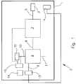
- the Fig. 1 shows a device 1 in an extracorporeal circuit 2.
- the device 1 has small-lumen cannulas 3, 4 for connection to a patient. These are shown here as single lumen cannulas but could be combined as a double lumen cannula.
- the device 1 comprises a tube system 5.
- an optional pump 7 is provided between the cannula 3 and a CO 2 -Eliminator 6 .
- the pump may be formed, for example, as a roller pump or centrifugal pump.
- an occlusive blood pump e.g. As a roller pump, be beneficial because the blood flow is largely independent of pressure ratios proportional to the pump speed. Thus, a measurement of blood flow may be unnecessary.
- the CO 2 eliminator 6 has a blood inlet 8 and a blood outlet 9. Furthermore, a gas inlet 10 and a gas outlet 11 are provided.
- the gas inlet 10 is connected to a purge gas reservoir 12, z.
- a gas blender or a gas cylinder connected as a gas line.
- At least one sensor 13 is arranged to detect parameters of the treated blood.
- the sensor 13 is connected to an evaluation device 14, which in turn is connected to a control device 15.
- various parameters of the CO 2 elimination process can be regulated as a function of the detected and evaluated parameters.
- the pump 7 can be regulated or the gas pressure of the purge gas.
- the control device 15 may be connected, for example, with a control valve between the purge gas reservoir 12 and the gas inlet 10.
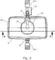
- the CO 2 -Eliminator 6 is shown in a plan view.
- a connector 8.1 is provided at the blood inlet and a connector 9.1 at the blood outlet.
- the sensor 13 is located between the blood outlet 9 and the connector 9.1.
- the sensor 13 is configured to detect temperature, blood flow, oxygen saturation, pCO 2 , pH, or other parameters of the treated blood.
- the CO 2 eliminator 6 has a housing 20. At the top of the housing a cover 21 is provided, on which the gas inlet 10 is arranged.
- the Fig. 3 shows a sectional view along the line AA of Fig. 2 ,
- a hollow fiber assembly 25 is provided which has a plurality of mats with hollow fibers.
- non-cast fibers are provided in an exchange-active region 26, while in an edge region 27 the fibers are cast and thus are not active for the gas exchange.
- the active fiber length is indicated by the letter Y, ie a dimension of the cross section which is active for the gas exchange.
- the total fiber length is X and also includes the region 27 in which the fibers are potted and thus do not participate in the gas exchange.
- the total length of the fibers is thus with X and the exchange-active fiber length or active fiber length indicated by Y.
- X the exchange-active fiber length or active fiber length indicated by Y.
- Y the exchange-active fiber length or active fiber length indicated by Y.
- the regions 28 there is inflowing purge gas and in the regions 30, 31 is gas after flowing through the hollow fiber assembly 25. From this illustration also shows that due to the arrangement of blood inlet 8 and blood outlet 9, the blood flow perpendicular to the arrangement of the fibers of the hollow fiber assembly 25 takes place.
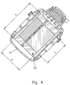
- the Fig. 4 shows a sectional view along the line BB of Fig. 3 , Here again the active fiber length Y and the entire fiber length X are shown. Furthermore, the thickness Z of the hollow fiber arrangement can be seen here.
- the thickness Z of the hollow fiber arrangement corresponds to the minimum distance of the blood passage, ie the shortest path that the blood can take through the hollow fiber arrangement.
- the blood flow takes place substantially at right angles to the orientation of the hollow fibers in the hollow fiber arrangement 25.
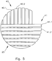
- the Fig. 5 shows a first (hollow fiber) mat 40 with a plurality of hollow fibers 40.1, 40.2, which are arranged parallel to each other. Furthermore, a second layer or mat 41 is shown with hollow fibers 41.1, 41.2, wherein the hollow fibers 41.1, 41.2 are arranged parallel to each other. However, the hollow fibers 40.1, 40.2 are arranged at right angles to the hollow fibers 41.1, 41.2. This means that the mats 40, 41 are layered crosswise.
- the purge gas supplied from the purge gas reservoir 12 enters via the input-side gas chambers 28, 29 and cut surfaces of the encapsulation in the region 27 in the hollow fibers 40.1, 40., 41.1, 41.2, passes their Inside, wherein the exchange active portion Y of the entire fiber length X causes the gas exchange. Subsequently, the gas exits at the cut surfaces of the casting in the region 27 into the outlet-side gas chambers 30, 31 and escapes via the gas outlet 11 located on the underside of the CO 2 -liminator 6.
- an exchange active surface of about 0.5 m 2 to 1.2 m 2 is sufficient.
- the exchange active hollow fibers can either be microporous or diffusive.
- This small quotient Y / Z which is not very different from 1, is the characteristic of a flow path which is optimized both on the gas side and on the gas side, and thus also for an optimized flow resistance for both media.
- the device described has the following design features: Surface for gas exchange: 1.3 m 2 Minimum active fiber length Y: 10.1 cm Total fiber length X: 12,7 cm Minimum distance of the blood passage Z 2.6 cm Maximum number of fibers 11712 Maximum number of fibers / m 2 9009
- the exchange-active fraction of the fibers is at least 79.5% and thus significantly higher than that of the device according to the invention.
- the gas exchange module at an active area of 0.98 m 2 contains at least 13119 hollow fibers or at least 13300 hollow fibers per m 2 : Surface for gas exchange: 0,98 m 2 Maximum active fiber length (Y): 5.8 cm Total fiber length (X): 7.6 cm Minimum distance of the blood passage (Z) 5,4 cm Minimum number of fibers 13119 Minimum number of fibers / m 2 13300
- This small quotient Y / Z which is not very different from 1, is the characteristic of a flow path which is optimized both on the gas side and on the gas side, and thus also for an optimized flow resistance for both media.
- the gas exchange module contains at least 17 148 hollow fibers or at least 17 497 hollow fibers per m 2 with an active area of 0.98 m 2 and use of hollow fibers at the lower limit of the specification (outer diameter 0.35 mm): Surface for gas exchange: 0,98 m 2 Maximum active fiber length (Y): 5.2 cm Total fiber length (X): 7.6 cm Minimum distance of the blood passage (Z) 5,4 cm Minimum number of fibers 17148 Minimum number of fibers / m 2 17497
- This small quotient Y / Z which is not very different from 1, is the characteristic of a flow path which is optimized both on the gas side and on the gas side, and thus also for an optimized flow resistance for both media.
Landscapes
- Health & Medical Sciences (AREA)
- Heart & Thoracic Surgery (AREA)
- Vascular Medicine (AREA)
- Anesthesiology (AREA)
- Hematology (AREA)
- Veterinary Medicine (AREA)
- Public Health (AREA)
- Engineering & Computer Science (AREA)
- General Health & Medical Sciences (AREA)
- Biomedical Technology (AREA)
- Cardiology (AREA)
- Life Sciences & Earth Sciences (AREA)
- Animal Behavior & Ethology (AREA)
- Chemical & Material Sciences (AREA)
- Chemical Kinetics & Catalysis (AREA)
- Emergency Medicine (AREA)
- Urology & Nephrology (AREA)
- Pulmonology (AREA)
- External Artificial Organs (AREA)
Description
- Die Erfindung betrifft eine Vorrichtung zur mindestens teilweisen Eliminierung von CO2 aus Patientenblut im extrakorporalen Kreislauf mit einem CO2-Eliminator, der ein Gehäuse mit einem Bluteinlass und einem Blutauslass sowie einem Gaseinlass und einem Gasauslass aufweist, wobei im Gehäuse eine sowohl vom Gas als auch Blut durchströmbare Hohlfaseranordnung mit einer aktiven Faserlänge vorgesehen ist.
- Die Erkrankung COPD (Chronic Obstructive Pulmonary Desease) führt zu einer Behinderung der Ausatmung und in Folge zu chronischer respiratorischer Insuffizienz. Die Symptome sind Atemnot und oft erhöhte pCO2-Werte. Bei dauerhaft erhöhten pCO2-Werten (Hyperkapnie, Ventilationsinsuffizienz) ist Hilfe über eine Beatmung möglich, die jedoch wegen des angewandten Überdrucks und der forcierten Füllung mit möglicher Überdehnung der Lunge zu Lungenschäden führen kann.
- Therapieverfahren wie die pumpenlose extrakorporale Lungenunterstützung (Interventional Lung Assist (iLA)) oder extracorporal membrane oxygenation (ECMO)) können in dieser Situation den Atemantrieb und die Atemarbeit reduzieren, sodass die Atemnot verschwindet und eine Erholung des Patienten möglich wird.
- Beispielsweise aus der
DE 200 11 060 U1 ist eine Vorrichtung zur Unterstützung der Lungenfunktion eines Patienten bekannt. Diese Vorrichtung ist auf einen sehr geringen Strömungswiderstand der Blutseite ausgelegt, sodass auf eine antreibende Pumpe bei arterio-venösem (A-V)-Anschluss verzichtet werden kann. Allerdings benötigt diese Vorrichtung einen Mindestblutfluss von 0,5 l pro Minute, um effektiv arbeiten zu können, und benötigt bei passivem AV-Betrieb verhältnismäßig großlumige Kanülen. Damit ist diese Vorrichtung nur bei einer großen Invasivität effektiv. Aufgrund ihrer Bauart ist diese Vorrichtung vorrangig als Oxygenator, bzw. bei verhältnismäßig hohem Blutfluss auch zur CO2-Eliminierung (Massentransfer) geeignet. - Das bekannte System hat den Nachteil, dass der Blutfluss abhängig von der AV-Druckdifferenz und dem blutseitigen Strömungswiderstand ist. Für eine gute Effizienz sind daher zwei getrennte Zugänge für die Zu- oder Abfuhr des Patientenblutes mit großlumigen Kanülen/Kathetern und Schlauchsystemen und entsprechenden Gefäßzugängen erforderlich, was eine hohe Invasivität bedingt. Dies bedeutet höheres Primingvolumen und stärkere Beeinträchtigung des Patienten durch die zusätzlichen größeren Wundflächen und eine Anwendung nur in der Intensivmedizin, wo solche Gefäßzugänge gelegt werden können. Zusätzlich muss der extrakorporale Kreislauf wegen des hohen Blutflusses intensiv überwacht werden, da bei einer Leckage oder Diskonnektierung innerhalb weniger Sekunden für den Patienten Lebensgefahr besteht.
- Die gleichen Aussagen gelten auch für die ECMO-Anwendungen von Oxygenatoren. Auch hier werden zwei getrennte Zugänge für die Zu- oder Abfuhr des Patientenblutes mit großlumigen Kanülen/Kathetern und Schlauchsystemen und entsprechende Gefäßzugänge benötigt, was eine hohe Invasivität bedingt. Wegen der hohen Invasivität von ECMO-Anwendungen werden diese oft als letzte lebenserhaltende Maßnahme angesehen und angewendet, was zu hoher Mortalität und deshalb zu einer eher schlechten Akzeptanz dieser an sich guten Behandlungsmethode führt.
- Aus der
EP 1 522 323 A1 ist eine Vorrichtung bekannt, die aus einem in einem Gehäuse integrierten Oxygenator mit nachgeschaltetem Dialysator besteht. In derEP 1 524 000 A8 wird die Anwendung einer solchen Vorrichtung in einem System zur kombinierten Hämodialyse und CO2-Eliminierung offenbart. - Aus der
EP 0 306 613 A1 und derJP 2000 084369 A - Die
DE 10 2009 008 601 A1 offenbart eine Vorrichtung zur Behandlung einer biologischen Flüssigkeit, umfassend mindestens drei Kammern, wobei eine erste Kammer, die zur Aufnahme der biologischen Flüssigkeit bestimmt ist, und eine zweite Kammer, die zur Aufnahme eines Gases bestimmt ist, durch mindestens eine gasdurchlässige und flüssigkeitsundurchlässige Membran voneinander getrennt sind. - Die
EP 1 864 709 A2 offenbart eine Vorrichtung, die in ihrem Innenraum einen Stapel von Membranmatten aufweist. - Aus der
DE 200 11 060 U1 ist eine Vorrichtung zur Unterstützung der Lungenfunktion eines Patienten bekannt. - Die
EP 1 810 704 A2 offenbart einen Oxygenator mit vorgeschaltetem Wärmetauscher und nachgeschaltetem Filter. - Die
EP 0 521 495 A2 offenbart eine Vorrichtung zur Stoffübertragung von einem Gas auf eine Flüssigkeit oder umgekehrt mittels geradlinig ausgebildeten Hohlfäden, bei welcher das Gas durch den Innenhohlraum der Hohlfäden strömt und die Endbereiche der Hohlfäden in einem Vergussmassekörper eingebettet sind. - Aufgabe der vorliegenden Erfindung ist es, eine Vorrichtung für die mindestens teilweise Eliminierung von CO2 bei Hyperkapnie bereitzustellen, die hohe Effektivität bei geringer Invasivität bietet.
- Gelöst wird diese Aufgabe erfindungsgemäß durch eine Vorrichtung zur zumindest teilweisen CO2-Eliminierung von Patientenblut im extrakorporalen Kreislauf mit den Merkmalen des Anspruchs 1.
- Dabei ist die aktive Faserlänge vorzugsweise eine Dimension des Querschnitts der Hohlfaseranordnung, der durch zu behandelndes Patientenblut durchströmbar ist. Die Wegstrecke der Blutpassage ist dabei der kürzeste Weg, den das zu behandelnde Blut durch die Hohlfaseranordnung nehmen kann. Insbesondere kann die minimale Wegstrecke der Blutpassage einer (weiteren) Dimension der Hohlfaseranordnung entsprechen. Die aktive Faserlänge und die minimale Wegstrecke können dabei einen Winkel von 90° zueinander aufweisen. Mit der erfindungsgemäßen Vorrichtung kann der CO2-Gehalt im Blut eines Patienten verringert werden.
- Die Hohlfasern sind dabei in Matten angeordnet, wobei die Fasern in den Matten parallel ausgerichtet sind. Die Matten sind in der Hohlfaseranordnung gestapelt, sodass die Fasern in parallelen benachbarten Matten in etwa rechtwinklig zu einander stehen. Die Wegstrecke bzw. die Blutflussrichtung ist im Wesentlichen rechtwinklig zur Faserorientierung. Die Hohlfasern können entweder vom mikroporösen oder vom diffusiven Typ sein. Beispiele für den mikroporösen bzw. diffusiven Typ sind die mikroporöse PP-Hohlfaser Oxyphan bzw. die diffusive PMP-Hohlfaser Oxyplus der Firma Membrana.
- Die Hohlfaseranordnung ist quaderförmig ausgebildet.
- Vorzugsweise handelt es sich bei der erfindungsgemäßen Vorrichtung um eine Vorrichtung ohne Wärmetauscher.
- Mit der erfindungsgemäßen Vorrichtung ist es möglich, die Parameter Blutfluss, Priming-Volumen und Druckverlust sowohl der Blut- als auch der Gasseite und die Größe des Eingriffs zum Gefäßzugang bei hoher Effektivität der CO2-Eliminierung zu minimieren. Insbesondere wurde festgestellt, dass mit der erfindungsgemäßen Vorrichtung schon bei geringem Blutfluss von 500 ml pro Minute eine effektive CO2-Eliminierung möglich ist. Aufgrund des geringen Blutflusses ist es möglich, mit kleinlumigen Kanülen oder sogar mit einer doppellumigen Kanüle zu arbeiten, die mit geringerer Invasivität beim Gefäßzugang, höherer Sicherheit durch bevorzugte venös-venös(W)-Kanülierung und damit verbundenem geringerem Blutdruckniveau und dadurch geringerem Überwachungsaufwand verbunden sind. Insbesondere ist es dadurch möglich, die erfindungsgemäße Vorrichtung nicht nur auf Intensivstationen zu verwenden. Das dem CO2-Eliminator über einen Gaseinlass zugeführte Spülgas kann grundsätzlich beliebig gewählt werden. Die Anforderungen sind lediglich toxikologische Unbedenklichkeit und weitgehende Freiheit von CO2. Insbesondere sind Luft oder Gemische von Luft mit Sauerstoff, Stickstoff oder Edelgasen geeignet, als Spülgas verwendet zu werden.
- Alternativ oder zusätzlich kann vorgesehen sein, dass der Quotient aus aktiver Faserlänge und Gesamtfaserlänge < 0,79, vorzugsweise < 0,77, bevorzugt 0,724 ± 5% ist. Die aktive Faseroberfläche der Hohlfaseranordnung ist im Bereich 0,5 bis 1,2 m2. Dabei weist die Hohlfaseranordnung mindestens 13.000, vorzugsweise mindestens 13.300 austauschaktive Fasern auf. Alternativ oder zusätzlich kann die Hohlfaseranordnung mindestens 13.300 Hohlfasern pro m2 aktive Austauschoberfläche aufweisen. Mit einer solchen Ausgestaltung der Hohlfaseranordnung ist es möglich, einen annähernden Gleichgewichtszustand zwischen dem pCO2 des Spülgases (nahe 0) und dem pCO2 des behandelten Blutes zu erreichen. Dies bedeutet eine Abkehr von im Stand der Technik üblichen physiologischen Werten für pCO2 (physiologischer Wert pCO2 32-46 mm Hg arteriell und 38-54 mm Hg venös) und pH-Wert (physiologischer Wert: pH 7,45-7,35 (arteriell-venös)).
- Während es bei Anwendungen mit Oxygenatoren bekannt ist, einen hohen Gastransfer (ml transferiertes Gas pro Zeit) durch höhere Blutflüsse und geringere Änderungen der Blutpartialdrücke der betrachteten Gase vor bzw. nach dem Gasaustausch im Rahmen physiologischer Werte und hoher Differenzen zwischen den Partialdrucken der Gase und Austauschgase und dem Blut zu erreichen, wird durch die erfindungsgemäße Vorrichtung eine andere Vorgehensweise ermöglicht.
- Die oben beschriebenen Gleichgewichtszustände sind mit bekannten Oxygenatoren nicht erreichbar, da diese optimiert wurden, um physiologisch normale Gaspartialdrücke aufrechtzuerhalten. Dabei wird über einen hohen Partialdruck von Sauerstoff im Versorgungsgas über den hohen vorliegenden Gradienten zwischen pO2 in der Gasphase und im Blut eine hohe Transferleistung bei einem relativ hohen Blutfluss bewirkt, wenn ein physiologischer Sauerstoffpartialdruck gefordert wird. Würde das Blut mit diesem Versorgungsgas ins Gleichgewicht gebracht, würden extrem hohe und damit unphysiologische Sauerstoffpartialdrücke erzielt werden. Auch die Eliminierung von CO2 bei der Blutoxygenierung soll bei bekannten Oxygenatoren zu physiologischen Konzentrationen am Ausgang des Oxygenators führen und nicht zu möglichst vollständiger Eliminierung von CO2. Daher wird bei der Zielsetzung von physiologischen Verhältnissen im Stand der Technik mit hohem Gradienten der durch Behandlung zu verändernden physikalischen, chemischen oder biologischen Parameter und relativ kleiner und damit kostengünstiger Austauschfläche gearbeitet, die eine Gleichgewichtseinstellung nicht ermöglicht.
- Versuche der Anmelderin haben überraschenderweise ergeben, dass bei geringen Blutflüssen die erfindungsgemäße Vorrichtung nahezu die gleiche Effektivität für die Entfernung von CO2 aufweist wie ein an Format, Priming-Volumen und Austauschoberfläche deutlich größeres Gasaustauschmodul. Weiterhin wurde festgestellt, dass sehr hohe Gasflüsse die Annäherung an Gleichgewichtszustände (niedriger pCO2 im Blut) fördern. Diese hohen Gasflüsse führen zu verhältnismäßig hohen Überdrücken, die bei Anwendungen von Oxygenatoren unüblich sind. Erreichen solche Überdrücke zwischen Gasseite und Blut den Bubble Point der Hohlfaseranordnung, ist der Übertritt von Gasbläschen ins Patientenblut möglich. Um solche kritischen Vorkommnisse zu vermeiden, sollte der Überdruck am Anfang der austauschaktiven Faser den Bubble Point nicht erreichen, bzw. der Überdruck auf der Gasseite sollte möglichst niedrig sein. Andererseits wurde festgestellt, dass größere Gasaustauschmodule selbst bei gleichem Gasfluss relativ zur vorhandenen Austauschfläche für die Entfernung von CO2 uneffektiver waren als der erfindungsgemäße kleinformatige CO2-Eliminator.
- Die erfindungsgemäßen Vorteile können insbesondere erzielt werden, indem anders als bei Oxygenatoren sehr viele, kurze Hohlfasern verwendet werden.
- Da durch den Verguss der Faserenden immer ein gewisser Prozentsatz der Hohlfaseranordnung für den Gasaustausch deaktiviert wird, wird im Stand der Technik versucht, diesen Prozentsatz durch Verwendung weniger, aber längerer Fasern gering zu halten.
- Erfindungsgemäß bieten jedoch viele, kurze Fasern für die weitgehende Gleichgewichtseinstellung (eine Gleichgewichtseinstellung wird angestrebt, aber in dynamischen Systemen nie vollständig erreicht) zwischen dem pCO2 des Spülgases (nahe 0) und dem pCO2 des behandelten Blutes überraschenderweise mehrere Vorteile. Durch die vielen kurzen parallel geschalteten Hohlfasern reduziert sich der Strömungswiderstand und damit der Überdruck auf der Gasseite bei hohen Gasflüssen auf unkritische Werte. Damit werden sehr hohe Gasflüsse möglich, die die Effizienz der CO2-Eliminierung fördern, ohne zu kritisch erhöhten Gasdrücken der Hohlfaseranordnung mit möglicher Gasblasenbildung im Blut zu führen. Das Spülgas erreicht während seiner Passage durch den kurzen austauschaktiven Teil der Hohlfaseranordnung durch Austausch nur geringe Werte von pCO2, sodass im Verlauf der Passage ein höherer Gradient zwischen pCO2 im Spülgas und im Blut erhalten bleibt. Eine längere Faser wäre durch einen höheren pCO2 des Spülgases im weiteren Verlauf der Passage aufgrund des geringeren Gradienten uneffektiv.
- Vorteilhafterweise kann zumindest ein Sensor zur Erfassung von Parametern des zu behandelnden Bluts vorgesehen sein. Insbesondere können die Sensoren in den CO2-Elminator integriert sein. Anhand der erfassten Parameter kann die Effektivität der CO2-Eliminierung überprüft werden. Ggf. kann der Gasfluss oder Blutfluss gesteuert oder geregelt werden.
- Besonders vorteilhaft ist es daher, wenn eine Auswerteeinrichtung vorgesehen ist, die mit dem zumindest einen Sensor verbunden ist und mit einer Regeleinrichtung zur Regelung zumindest eines Parameters des extrakorporalen Kreislaufs in Verbindung steht.
- Gemäß einer Ausgestaltung der Erfindung kann vorgesehen sein, dass mindestens zwei Kanülen (einlumige Kanülen) mit je einem Lumen < 21 French, bevorzugt mit je einem Lumen von 13 French, oder mindestens eine doppellumige Kanüle mit zwei Lumen < 24 French, bevorzugt mit Lumen von 19 French, vorgesehen sind. Durch diese Maßnahme kann die Invasivität vermindert werden.
- Offenbart ist auch ein Verfahren zum Betrieb einer erfindungsgemäßen Vorrichtung, wobei ein Gleichgewicht zwischen dem pCO2 des eintretenden Spülgases und dem pCO2 des behandelten Bluts angestrebt wird. Dadurch kann eine sehr hohe Effektivität der CO2-Eliminierung bei geringer Invasivität erreicht werden. Insbesondere können kleinlumige, insbesondere doppellumige veno-venöse Kanülen bei geringem Blutfluss eingesetzt werden. Durch die entsprechende Einstellung des Gleichgewichts lässt sich bei geringem Blutfluss eine weitgehende Befreiung des behandelten Bluts von CO2 erreichen. Insbesondere kann ein pCO2 des behandelten Bluts < 32 mm Hg, bevorzugt < 25 mm Hg, besonders bevorzugt < 15 mm Hg eingestellt werden, ein Wert, der selbst für arterielles Blut unphysiologisch ist und mit einem pH-Wert > 7,45, bevorzugt pH >7,6, besonders bevorzugt pH 7,8 einhergeht, was als respiratorische Alkalose bezeichnet wird.
- In Versuchen der Anmelderin wurden beispielsweise pCO2-Werte im Bereich von 10-15 mm Hg bei pH-Werten um etwa pH 7,8 im behandelten Blut ermittelt.
- Bevorzugt ist es, wenn die Vorrichtung mit einem Blutfluss < 1200 ml pro Minute, besonders bevorzugt < 800 ml pro Minute, insbesondere < 500 ml pro Minute, betrieben wird. Dadurch senkt sich das Risiko für den behandelten Patienten. Außerdem können Kanülen und Leitungen mit geringerem Durchmesser verwendet werden.
- Wie bereits erwähnt, kann vorteilhafterweise ein pH-Wert des behandelten Blutes > 7,45 eingestellt werden.
- Hiermit wird auf die
US-Patentanmeldung 61802335 - Weitere Merkmale und Vorteile der Erfindung ergeben sich aus der nachfolgenden Beschreibung eines Ausführungsbeispiels der Erfindung.
- Es zeigen:
- Fig. 1
- eine stark schematisierte Darstellung einer erfindungsgemäßen Vorrichtung;
- Fig. 2
- eine Ansicht von oben auf einen CO2-Eliminator;
- Fig. 3
- eine Schnittdarstellung durch den CO2-Eliminator gemäß der Linie A-A der
Fig. 2 ; - Fig. 4
- eine Schnittdarstellung gemäß der Linie B-B der
Fig. 3 ; - Fig. 5
- eine stark schematisierte Darstellung eines Ausschnitts einer Hohlfaseranordnung .
- Die
Fig. 1 zeigt eine Vorrichtung 1 in einem extrakorporalen Kreislauf 2. Die Vorrichtung 1 weist kleinlumige Kanülen 3, 4 zur Verbindung mit einem Patienten auf. Diese sind hier als einlumige Kanülen gezeigt, könnten jedoch als doppellumige Kanüle kombiniert sein. Weiterhin umfasst die Vorrichtung 1 ein Schlauchsystem 5. Zwischen der Kanüle 3 und einem CO2-Eliminator 6 ist eine optionale Pumpe 7 vorgesehen. Die Pumpe kann beispielsweise als Rollerpumpe oder Zentrifugalpumpe ausgebildet sein. Bei der vorliegenden Anwendung kann eine okklusive Blutpumpe, z. B. eine Rollerpumpe, von Vorteil sein, da der Blutfluss weitgehend unabhängig von Druckverhältnissen proportional zu der Pumpendrehzahl ist. Somit kann sich eine Messung des Blutflusses erübrigen. - Der CO2-Eliminator 6 weist einen Bluteinlass 8 und einen Blutauslass 9 auf. Weiterhin sind ein Gaseinlass 10 und ein Gasauslass 11 vorgesehen. Der Gaseinlass 10 ist an ein Spülgasreservoir 12, z. B. eine Gasleitung, ein Gasblender oder eine Gasflasche, angeschlossen.
- Im Bereich des Blutauslasses 9 ist zumindest ein Sensor 13 angeordnet zur Erfassung von Parametern des behandelten Bluts. Der Sensor 13 ist mit einer Auswerteeinrichtung 14 verbunden, die wiederum mit einer Regeleinrichtung 15 verbunden ist. Durch die Regeleinrichtung 15 können in Abhängigkeit von den erfassten und ausgewerteten Parametern verschiedene Parameter des CO2-Eliminierungsprozesses geregelt werden. Beispielsweise kann die Pumpe 7 geregelt werden oder der Gasdruck des Spülgases. Hierzu kann die Regeleinrichtung 15 beispielsweise mit einem Regelventil zwischen dem Spülgasreservoir 12 und dem Gaseinlass 10 verbunden sein.
- In der
Fig. 2 ist der CO2-Eliminator 6 in einer Draufsicht gezeigt. Hier ist zu erkennen, dass am Bluteinlass ein Konnektor 8.1 und am Blutauslass ein Konnektor 9.1 vorgesehen sind. Der Sensor 13 befindet sich dabei zwischen dem Blutauslass 9 und dem Konnektor 9.1. Der Sensor 13 ist beispielsweise eingerichtet, Temperatur, Blutfluss, Sauerstoffsättigung, pCO2, pH oder andere Parameter des behandelten Bluts zu erfassen. - Der CO2-Eliminator 6 weist ein Gehäuse 20 auf. Oben an dem Gehäuse ist ein Deckel 21 vorgesehen, an dem der Gaseinlass 10 angeordnet ist.
- Die
Fig. 3 zeigt eine Schnittdarstellung gemäß der Linie A-A derFig. 2 . Insbesondere ist hier zu erkennen, dass im Inneren des Gehäuses 20 des CO2-Eliminators 6 eine Hohlfaseranordnung 25 vorgesehen ist, die mehrere Matten mit Hohlfasern aufweist. Dabei sind in einem austauschaktiven Bereich 26 unvergossene Fasern vorgesehen, während in einem Randbereich 27 die Fasern vergossen sind und somit nicht für den Gasaustausch aktiv sind. Die aktive Faserlänge ist dabei mit dem Buchstaben Y angegeben, d. h. einer Dimension des Querschnitts, der für den Gasaustausch aktiv ist. Die gesamte Faserlänge beträgt dagegen X und beinhaltet auch den Bereich 27, in dem die Fasern vergossen sind und somit nicht am Gasaustausch teilnehmen. Die Gesamtlänge der Fasern ist somit mit X und die austauschaktive Faserlänge bzw. aktive Faserlänge mit Y angegeben. In den Bereichen 28 befindet sich einströmendes Spülgas und in den Bereichen 30, 31 befindet sich Gas nach Durchströmen der Hohlfaseranordnung 25. Aus dieser Darstellung ergibt sich auch, dass aufgrund der Anordnung von Bluteinlass 8 und Blutauslass 9 der Blutfluss senkrecht zur Anordnung der Fasern der Hohlfaseranordnung 25 erfolgt. - Aus der Darstellung der
Fig. 3 ergibt sich weiterhin, dass die Hohlfaseranordnung aus zwei (orthogonalen) Richtungen durchströmt wird, nämlich von den Bereichen 28, 29 aus. - Die
Fig. 4 zeigt eine Schnittdarstellung gemäß der Linie B-B derFig. 3 . Hier sind wiederum die aktive Faserlänge Y und die gesamte Faserlänge X eingezeichnet. Weiterhin ist hier die Dicke Z der Hohlfaseranordnung zu sehen. Die Dicke Z der Hohlfaseranordnung entspricht dabei der minimalen Wegstrecke der Blutpassage, d.h. dem kürzesten Weg, den das Blut durch die Hohlfaseranordnung nehmen kann. Der Blutfluss erfolgt hierbei im Wesentlichen rechtwinklig zur Ausrichtung der Hohlfasern in der Hohlfaseranordnung 25. - Die
Fig. 5 zeigt eine erste (Hohlfaser-)Matte 40 mit mehreren Hohlfasern 40.1, 40.2, die parallel zueinander angeordnet sind. Weiterhin ist eine zweite Schicht oder Matte 41 mit Hohlfasern 41.1, 41.2 gezeigt, wobei auch die Hohlfasern 41.1, 41.2 parallel zueinander angeordnet sind. Die Hohlfasern 40.1, 40.2 sind jedoch rechtwinklig zu den Hohlfasern 41.1,41.2 angeordnet. Dies bedeutet, dass die Matten 40, 41 kreuzweise geschichtet sind. - Das von dem Spülgasreservoir 12 zugeführte Spülgas tritt über die eingangsseitigen Gasräume 28, 29 und Schnittflächen des Vergusses im Bereich 27 in die Hohlfasern 40.1, 40., 41.1, 41.2 ein, passiert deren Innenseite, wobei der austauschaktive Anteil Y der gesamten Faserlänge X den Gasaustausch bewirkt. Anschließend tritt das Gas an den Schnittflächen des Vergusses im Bereich 27 in die ausgangsseitigen Gasräume 30, 31 aus und entweicht über den an der Unterseite des CO2-Eliminators 6 befindlichen Gasauslass 11.
- Zur effektiven Eliminierung von CO2 eines Blutflusses von etwa 500 ml pro Minute ist eine austauschaktive Oberfläche von etwa 0,5 m2 bis 1,2 m2 ausreichend. Die austauschaktiven Hohlfasern können entweder mikroporös oder diffusiv sein.
- Besonders gute Ergebnisse wurden mit einem CO2-Eliminator gemäß Ausführungsbeispiel 1 erzielt, dessen Hohlfaseranordnung eine aktive Fläche von 0,98 m2 und mindestens 13 834 Hohlfasern bzw. mindestens 14116 Hohlfasern pro m2 aufwies:
Ausführungsbeispiel 1: Oberfläche für Gasaustausch: 0,98 m2 Maximale aktive Faserlänge (Y) : 5,5 cm Gesamtfaserlänge (X) : 7,6 cm Minimale Wegstrecke der Blutpassage (Z) 5,4 cm Minimale Faseranzahl 13834 Minimale Faseranzahl/m2 14116 - Daraus berechnet sich ein Quotient der maximalen aktiven Faserlänge (Y) und der minimalen Wegstrecke der Blutpassage (Z)
von Y/Z = 5,5 cm / 5,4 cm = 1,02. - Dieser kleine, nicht stark von 1 abweichende Quotient Y/Z ist das Kennzeichen eines sowohl blutseitig als auch gasseitig optimierten Strömungsweges und dadurch auch eines für beide Medien optimierten Strömungswiderstands.
- Ein weiteres Merkmal der erfindungsgemäßen Vorrichtung ist der Quotient der maximalen aktiven Faserlänge (Y) und der Gesamtfaserlänge (X): Y/X= 5,5 cm/7,6 cm = 0,724. Das bedeutet, dass der austauschaktive Anteil der Fasern maximal 72,4% beträgt.
- Die in
DE 2011060U1 beschriebene Vorrichtung dagegen weist die folgenden Konstruktionsmerkmale auf:Oberfläche für Gasaustausch: 1,3 m2 Minimale aktive Faserlänge Y: 10,1 cm Gesamtfaserlänge X : 12,7 cm Minimale Wegstrecke der Blutpassage Z 2,6 cm Maximale Faseranzahl 11712 Maximale Faseranzahl/m2 9009 - Daraus berechnet sich ein Quotient der aktiven Faserlänge (Y) und der minimalen Wegstrecke der Blutpassage (Z)
von Y/Z = 10,1 cm / 2,6 cm = 3,88. - Dieser deutlich höhere Quotient Y/Z zeigt an, dass in diesem Fall der geringe Strömungswiderstand des Blutes das Entwicklungsziel war.
- Der Quotient der minimalen aktiven Faserlänge (Y) und der Gesamtfaserlänge (X) beträgt in diesem Fall:
Y/X = 10,1 cm/12,7cm = 0,795. - Das bedeutet, dass der austauschaktive Anteil der Fasern minimal 79,5% beträgt und damit deutlich höher ist, als der der erfindungsgemäßen Vorrichtung.
- In einer weiteren Ausführung enthält das Gasaustauschmodul bei einer aktiven Fläche von 0,98 m2 mindestens 13119 Hohlfasern bzw. mindestens 13300 Hohlfasern pro m2:
Oberfläche für Gasaustausch: 0,98 m2 Maximale aktive Faserlänge (Y) : 5,8 cm Gesamtfaserlänge (X) : 7,6 cm Minimale Wegstrecke der Blutpassage (Z) 5,4 cm Minimale Faseranzahl 13119 Minimale Faseranzahl/m2 13300 - Daraus berechnet sich ein Quotient der maximalen aktiven Faserlänge (Y) und der minimalen Wegstrecke der Blutpassage (Z)
von Y/Z = 5,8 cm / 5,4 cm = 1,07. - Dieser kleine, nicht stark von 1 abweichende Quotient Y/Z ist das Kennzeichen eines sowohl blutseitig als auch gasseitig optimierten Strömungsweges und dadurch auch eines für beide Medien optimierten Strömungswiderstands.
- Der Quotient der maximalen aktiven Faserlänge (Y) und der Gesamtfaserlänge (X) beträgt:
Y/X = 5,8 cm/7,6 cm = 0,763.
Das bedeutet, dass der austauschaktive Anteil der Fasern maximal 76,3% beträgt. - In einer weiteren Ausführung enthält das Gasaustauschmodul bei einer aktiven Fläche von 0,98 m2 und Verwendung von Hohlfasern an der unteren Grenze der Spezifikation (Außendurchmesser 0,35 mm) mindestens 17 148 Hohlfasern bzw. mindestens 17 497 Hohlfasern pro m2:
Oberfläche für Gasaustausch: 0,98 m2 Maximale aktive Faserlänge (Y) : 5,2 cm Gesamtfaserlänge (X) : 7,6 cm Minimale Wegstrecke der Blutpassage (Z) 5,4 cm Minimale Faseranzahl 17148 Minimale Faseranzahl/m2 17497 - Daraus berechnet sich ein Quotient der maximalen aktiven Faserlänge (Y) und der minimalen Wegstrecke der Blutpassage (Z)
von Y/Z = 5,2 cm / 5,4 cm = 0,963. - Dieser kleine, nicht stark von 1 abweichende Quotient Y/Z ist das Kennzeichen eines sowohl blutseitig als auch gasseitig optimierten Strömungsweges und dadurch auch eines für beide Medien optimierten Strömungswiderstands.
- Der Quotient der maximalen aktiven Faserlänge (Y) und der Gesamtfaserlänge (X) beträgt:
Y/X = 5,2 cm/7,6 cm = 0,684.
Claims (7)
- Vorrichtung (1) zur zumindest teilweisen CO2 -Eliminierung von Patientenblut im extrakorporalen Kreislauf (2) mit einem CO2-Eliminator (6), der ein Gehäuse (20) mit einem Bluteinlass (8) und einem Blutauslass (9) sowie einem Gaseinlass (10) und einem Gasauslass (11) aufweist, wobei im Gehäuse (20) eine sowohl von Gas als auch Blut durchströmbare Hohlfaseranordnung (25) mit einer für den Gasaustausch aktiven Faserlänge (Y) als Anteil einer Gesamtfaserlänge (X) vorgesehen ist, wobei die Hohlfasern in Matten angeordnet sind, wobei die Fasern in den Matten parallel ausgerichtet sind und die Matten in der Hohlfaseranordnung gestapelt sind, sodass die Fasern in parallelen benachbarten Matten in etwa rechtwinklig zueinander stehen, und dass die Wegstrecke der Blutpassage, die der Dicke (Z) der Hohlfaseranordnung (25) entspricht, im Wesentlichen rechtwinklig zur Faserorientierung und auf kürzestem Wege durch die Hohlfaseranordnung (25) verläuft, wobei die Hohlfaseranordnung (25) quaderförmig ausgebildet ist und der Quotient aus aktiver Faserlänge (Y) und minimaler Wegstrecke (Z) der Blutpassage durch die Hohlfaseranordnung (25) kleiner 3,5, vorzugsweise kleiner 3, besonders bevorzugt kleiner 2, ganz besonders bevorzugt kleiner 1,1 ist, wobei in einem austauschaktiven Bereich (26) unvergossene Fasern vorgesehen, während in einem Randbereich (27) die Fasern vergossen sind und somit nicht für den Gasaustausch aktiv sind, wobei die Hohlfaseranordnung (25) einen quadratischen Querschnitt aufweist, dessen Seitenlänge der Gesamtfaserlänge (X) entspricht und der austauschaktive Bereich (26) einen quadratischen Querschnitt aufweist, dessen Seitenlänge der aktiven Faserlänge (Y) entspricht, dadurch gekennzeichnet, dass die für den Gasaustausch aktive Faseroberfläche der Hohlfaseranordnung im Bereich 0,5 - 1,2 m2 liegt.
- Vorrichtung nach Anspruch 1, dadurch gekennzeichnet, dass der Quotient aus aktiver Faserlänge (Y) und Gesamtfaserlänge (X) kleiner 0,79, vorzugsweise kleiner 0,77, bevorzugt 0,724 +/- 5% ist.
- Vorrichtung nach einem der vorhergehenden Ansprüche, dadurch gekennzeichnet, dass die Hohlfaseranordnung (25) mindestens 13300 Hohlfasern (40.1, 40.2, 41.1, 41.2) pro m2 aktive Austauschoberfläche aufweist.
- Vorrichtung nach einem der vorhergehenden Ansprüche, dadurch gekennzeichnet, dass zumindest ein Sensor (13) zur Erfassung von Parametern des behandelten Bluts vorgesehen ist.
- Vorrichtung nach Anspruch 4, dadurch gekennzeichnet, dass eine Auswerteeinrichtung(14) vorgesehen ist, die mit dem zumindest einen Sensor (13) verbunden ist und mit einer Regeleinrichtung (15) zur Regelung zumindest eines Parameters des extrakorporalen Kreislaufs (2) in Verbindung steht.
- Vorrichtung nach einem der vorhergehenden Ansprüche, dadurch gekennzeichnet, dass Kanülen (3, 4) mit einem Lumen kleiner als 21 French, bevorzugt von 13 French, oder doppellumige Kanülen (3, 4) mit einem Lumen kleiner als 24 French, bevorzugt 19 French, vorgesehen sind.
- Vorrichtung nach einem der vorhergehenden Ansprüche, dadurch gekennzeichnet, dass sie keinen Wärmetauscher aufweist.
Priority Applications (5)
| Application Number | Priority Date | Filing Date | Title |
|---|---|---|---|
| PCT/IB2014/001600 WO2014177944A2 (en) | 2013-03-15 | 2014-03-14 | Carbon dioxide removal system |
| KR1020157027326A KR102318993B1 (ko) | 2013-03-15 | 2014-03-14 | 이산화탄소 제거 시스템 |
| KR1020217034453A KR102401097B1 (ko) | 2013-03-15 | 2014-03-14 | 이산화탄소 제거 시스템 |
| CN201480024198.5A CN105451788B (zh) | 2013-03-15 | 2014-03-14 | 二氧化碳去除系统 |
| US14/854,926 US10201649B2 (en) | 2013-03-15 | 2015-09-15 | Carbon dioxide removal system |
Applications Claiming Priority (1)
| Application Number | Priority Date | Filing Date | Title |
|---|---|---|---|
| US201361802335P | 2013-03-15 | 2013-03-15 |
Publications (3)
| Publication Number | Publication Date |
|---|---|
| EP2777801A2 EP2777801A2 (de) | 2014-09-17 |
| EP2777801A3 EP2777801A3 (de) | 2014-11-26 |
| EP2777801B1 true EP2777801B1 (de) | 2019-08-28 |
Family
ID=48444195
Family Applications (1)
| Application Number | Title | Priority Date | Filing Date |
|---|---|---|---|
| EP13168103.3A Active EP2777801B1 (de) | 2013-03-15 | 2013-05-16 | Vorrichtung zur CO2-Eliminierung von Patientenblut |
Country Status (6)
| Country | Link |
|---|---|
| US (1) | US10201649B2 (de) |
| EP (1) | EP2777801B1 (de) |
| JP (5) | JP6770803B2 (de) |
| KR (2) | KR102401097B1 (de) |
| CN (1) | CN105451788B (de) |
| WO (1) | WO2014177944A2 (de) |
Families Citing this family (19)
| Publication number | Priority date | Publication date | Assignee | Title |
|---|---|---|---|---|
| EP3090769A1 (de) | 2015-05-07 | 2016-11-09 | Novalung GmbH | Tragbare gasaustauschvorrichtung |
| WO2017062549A1 (en) * | 2015-10-07 | 2017-04-13 | MAQUET CARDIOPULMONARY GmbH | User interface |
| DE102016015059B4 (de) | 2016-12-19 | 2020-11-12 | Drägerwerk AG & Co. KGaA | Vorrichtung zum extrakorporalen Blutgasaustausch |
| DE102017000940A1 (de) | 2017-02-02 | 2018-08-02 | Xenios Ag | Anordnung mit einer Blutpumpe, einer Steuereinheit und einem Gerät zur Übermittlung der Messwerte |
| DE102017131192A1 (de) | 2017-12-22 | 2019-06-27 | Fresenius Medical Care Deutschland Gmbh | Pufferlösung zur Reduzierung des Kohlendioxidgehaltes in extrakorporalem Blut |
| GB2574015A (en) * | 2018-05-22 | 2019-11-27 | Spectrum Medical Ltd | Blood processing system |
| IT201800005692A1 (it) * | 2018-05-24 | 2019-11-24 | Dispositivo per la misurazione della anidride carbonica in un gas di lavoro | |
| JP7278648B2 (ja) | 2019-01-25 | 2023-05-22 | トランソニック システムズ インク | 静静脈体外式血液酸素供給における心拍出量を計算するための装置 |
| US11633525B2 (en) | 2019-01-29 | 2023-04-25 | Transonic Systems Inc. | Method and apparatus for assessing cardiac output in veno-arterial extracorporeal blood oxygenation |
| JP7460645B2 (ja) * | 2019-02-26 | 2024-04-02 | オウビ・アーペーエス | 酸素治療を受ける患者に関して判断支援を提供する方法 |
| US11654218B2 (en) * | 2019-05-02 | 2023-05-23 | Transonic Systems Inc. | Calculating cardiac output of a patient undergoing veno-venous extracorporeal blood oxygenation |
| CA3235847A1 (en) * | 2019-10-25 | 2021-04-29 | MAQUET CARDIOPULMONARY GmbH | A working fluid treatment device for mass transfer between a working fluid and two fluid exchange media |
| US12478292B2 (en) | 2019-10-28 | 2025-11-25 | The Research Foundation For The State University Of New York | Devices, systems, and methods of monitoring arterial carbon dioxide |
| USD1002014S1 (en) * | 2020-08-31 | 2023-10-17 | MAQUET CARDIOPULMONARY GmbH | Universal holder system |
| USD1073948S1 (en) * | 2020-08-31 | 2025-05-06 | MAQUET CARDIOPULMONARY GmbH | Universal holder system |
| USD1087346S1 (en) * | 2020-08-31 | 2025-08-05 | MAQUET CARDIOPULMONARY GmbH | Universal holder system |
| US20230372594A1 (en) * | 2022-05-18 | 2023-11-23 | Stavro Medical, Inc. | Single lumen hybrid connection to legacy system |
| JP2023177563A (ja) * | 2022-06-02 | 2023-12-14 | 泉工医科工業株式会社 | 人工肺 |
| CN116747368A (zh) * | 2023-06-08 | 2023-09-15 | 苏州肺盾医疗科技有限公司 | 氧合器及体外膜肺氧合装置 |
Citations (1)
| Publication number | Priority date | Publication date | Assignee | Title |
|---|---|---|---|---|
| EP0521495A2 (de) * | 1991-07-05 | 1993-01-07 | Akzo Nobel N.V. | Verfahren und Vorrichtung zum Herstellen von Hohlfadenmodulen |
Family Cites Families (49)
| Publication number | Priority date | Publication date | Assignee | Title |
|---|---|---|---|---|
| GB1267105A (de) | 1968-12-02 | 1972-03-15 | ||
| FR2197565B1 (de) | 1972-08-30 | 1975-03-07 | Rhone Poulenc Ind | |
| US3890969A (en) | 1974-01-21 | 1975-06-24 | Baxter Laboratories Inc | Cardiopulmonary bypass system |
| GB1595058A (en) | 1976-10-22 | 1981-08-05 | Bellhouse Brian John | Membrane blood oxygenators |
| JPS573652A (en) | 1980-06-06 | 1982-01-09 | Kanegafuchi Chemical Ind | Artificial lung using minute hole diameter film |
| US4620965A (en) * | 1982-09-22 | 1986-11-04 | Terumo Corporation | Hollow fiber-type artificial lung |
| JPS61128978A (ja) * | 1984-11-27 | 1986-06-17 | テルモ株式会社 | 膜型人工肺 |
| US4698207A (en) | 1986-07-14 | 1987-10-06 | Baxter Travenol Laboratories, Inc. | Integrated membrane oxygenator, heat exchanger and reservoir |
| JPH0696098B2 (ja) * | 1988-05-27 | 1994-11-30 | 株式会社クラレ | 中空糸型流体処理装置 |
| JPH0724742B2 (ja) | 1988-07-25 | 1995-03-22 | テルモ株式会社 | ポリプロピレン多孔質中空糸膜およびその製造方法 |
| JPH0798061B2 (ja) * | 1989-02-13 | 1995-10-25 | 株式会社クラレ | 血液処理装置 |
| JPH03158167A (ja) * | 1989-11-15 | 1991-07-08 | Terumo Corp | 人工肺 |
| US5270005A (en) | 1990-09-07 | 1993-12-14 | Baxter International Inc. | Extracorporeal blood oxygenation system incorporating integrated reservoir-membrane oxygenerator-heat exchanger and pump assembly |
| WO1993015827A1 (fr) | 1992-02-12 | 1993-08-19 | Mitsubishi Rayon Co., Ltd. | Module de membranes a fils creux |
| US5411706A (en) | 1994-02-09 | 1995-05-02 | Hubbard; Lloyd C. | Pump/oxygenator with blood recirculation |
| DE69632422T2 (de) | 1995-08-11 | 2005-05-19 | Zenon Environmental Inc., Oakville | Verfahren zum Einbetten von Hohlfaser-Membranen |
| US6866755B2 (en) | 2001-08-01 | 2005-03-15 | Battelle Memorial Institute | Photolytic artificial lung |
| JP3803421B2 (ja) * | 1996-04-26 | 2006-08-02 | 富士システムズ株式会社 | 気体交換装置 |
| US5865789A (en) | 1997-07-23 | 1999-02-02 | Hattler; Brack G. | Percutaneous oxygenator for inducing a retrograde perfusion of oxygenated blood |
| JP4026037B2 (ja) * | 1998-09-10 | 2007-12-26 | 大日本インキ化学工業株式会社 | 中空糸膜型気液ガス交換装置及びそのガス交換方法 |
| DE20011060U1 (de) | 2000-06-23 | 2000-09-28 | JOSTRA AG, 72145 Hirrlingen | Vorrichtung zur Unterstützung der Lungenfunktion eines Patienten |
| US20020143397A1 (en) | 2001-04-02 | 2002-10-03 | Von Segesser Ludwig K. | Compliant artificial lung for extrapulmonary gas transfer |
| US7909788B2 (en) | 2001-08-01 | 2011-03-22 | Battelle Memorial Institute | Carbon dioxide removal from whole blood by photolytic activation |
| US6682698B2 (en) * | 2001-08-23 | 2004-01-27 | Michigan Critical Care Consultants, Inc. | Apparatus for exchanging gases in a liquid |
| US20030133835A1 (en) | 2002-01-16 | 2003-07-17 | Hattler Brack G. | Intravenous oxygenator having an impeller |
| DE50308855D1 (de) | 2002-07-22 | 2008-01-31 | Novalung Gmbh | Intravenöser oxygenator |
| DE10261575A1 (de) | 2002-12-23 | 2004-07-08 | Nova Lung Gmbh | Vorrichtung zur Kanülierung eines Blut führenden Gefäßes und deren Verwendung zur Kanülierung von Blut führenden Gefäßen |
| ITTO20030785A1 (it) | 2003-10-03 | 2005-04-04 | Mri S R L Societa Unipersonale | Unita' di filtraggio del sangue in una macchina per emofiltrazione. |
| ITFI20030256A1 (it) | 2003-10-09 | 2005-04-10 | Angela Caramuta | Dispositivo per l'eliminazione dell'anidride carbonica |
| ITFI20040025A1 (it) | 2004-02-05 | 2004-05-05 | Angela Caramuta | Dispositivo per l'eliminazione dell'anidride carbonica dal sangue ed un'apparecchiatura equipaggiata con il dispositivo medesimo |
| EP1649883A1 (de) | 2004-10-19 | 2006-04-26 | MRI S.r.l. Società Unipersonale | Vorrichtung zur Entfernung von Kohlendioxid aus dem Blut oder aus einer Flüssigkeit kommend aus dem Herzkreislaufsystem eines Patienten |
| EP1649882A1 (de) | 2004-10-19 | 2006-04-26 | MRI S.r.l. Società Unipersonale | Vorrichtung zur Entfernung von Kohlendioxid aus dem Blut |
| EP2295133B8 (de) * | 2005-04-21 | 2014-07-30 | University of Pittsburgh - Of The Commonwealth System of Higher Education | Extrakorporaler Oxygenator |
| DE102005031582A1 (de) | 2005-07-06 | 2007-01-11 | Maquet Cardiopulmonary Ag | Vorrichtung zur Behandlung von Blut in einem extrakorporalen Blutkreislauf |
| DE102005045663A1 (de) | 2005-09-13 | 2007-03-22 | Novalung Gmbh | Vorrichtung zur Unterbrechung eines durch einen Hohlkörper fließenden Blutstroms in einem extrakorporalen Blutkreislauf |
| JP4874088B2 (ja) * | 2006-01-19 | 2012-02-08 | テルモ株式会社 | 人工肺 |
| EP2335752B1 (de) * | 2006-01-19 | 2016-09-14 | Terumo Kabushiki Kaisha | Oxygenator |
| DE102006016211A1 (de) | 2006-04-03 | 2007-10-04 | Novalung Gmbh | Kupplung für rohrförmige Elemente |
| DE102006020492A1 (de) | 2006-04-21 | 2007-10-25 | Novalung Gmbh | Verwendung von Acetylsalicylsäure (ASS) beim Einsatz einer Membranlunge |
| US8585968B2 (en) | 2006-04-21 | 2013-11-19 | Scott W. Morley | Method and system for purging moisture from an oxygenator |
| DE102006020494A1 (de) | 2006-04-21 | 2007-10-25 | Novalung Gmbh | Künstliches Lungensystem und dessen Verwendung |
| DE102006021066B4 (de) | 2006-05-05 | 2009-06-25 | Fresenius Medical Care Deutschland Gmbh | Verfahren und Vorrichtung zum Einbringen einer Vergußmasse in eine Filtervorrichtung |
| US7641795B2 (en) * | 2006-06-05 | 2010-01-05 | Celgard Llc | Membrane contactor |
| DE102006042639A1 (de) | 2006-09-01 | 2008-03-20 | Novalung Gmbh | Vorrichtung zur Kanülierung eines Blut-führenden Gefäßes |
| ITMI20070913A1 (it) | 2007-05-07 | 2008-11-08 | Antonio Pesenti | Metodo di trattamento del sangue atto ad eliminare almeno parzialmente il contenuto di anidride carbonica e relativo dispositivo. |
| DE102007038121A1 (de) | 2007-07-31 | 2009-02-05 | Novalung Gmbh | Konditionierung von Blut eines Patienten durch Gase |
| DE102008024835A1 (de) | 2008-05-23 | 2009-12-10 | Maquet Cardiopulmonary Ag | Universell anwendbares optimiertes Perfusionssystem |
| DE102008045621A1 (de) | 2008-09-03 | 2010-03-04 | Novalung Gmbh | Gastransfervorrichtung und Verwendung einer strukturierten Membran |
| DE102009008601A1 (de) | 2009-02-12 | 2010-08-19 | Novalung Gmbh | Vorrichtung zur Behandlung einer biologischen Flüssigkeit |
-
2013
- 2013-05-16 EP EP13168103.3A patent/EP2777801B1/de active Active
-
2014
- 2014-03-14 WO PCT/IB2014/001600 patent/WO2014177944A2/en not_active Ceased
- 2014-03-14 JP JP2015562424A patent/JP6770803B2/ja active Active
- 2014-03-14 KR KR1020217034453A patent/KR102401097B1/ko active Active
- 2014-03-14 KR KR1020157027326A patent/KR102318993B1/ko active Active
- 2014-03-14 CN CN201480024198.5A patent/CN105451788B/zh active Active
-
2015
- 2015-09-15 US US14/854,926 patent/US10201649B2/en active Active
-
2018
- 2018-05-28 JP JP2018101363A patent/JP2018158122A/ja active Pending
-
2019
- 2019-02-21 JP JP2019029444A patent/JP7232664B2/ja active Active
- 2019-11-01 JP JP2019199802A patent/JP2020014939A/ja not_active Withdrawn
-
2021
- 2021-09-22 JP JP2021153919A patent/JP2021191539A/ja active Pending
Patent Citations (1)
| Publication number | Priority date | Publication date | Assignee | Title |
|---|---|---|---|---|
| EP0521495A2 (de) * | 1991-07-05 | 1993-01-07 | Akzo Nobel N.V. | Verfahren und Vorrichtung zum Herstellen von Hohlfadenmodulen |
Also Published As
| Publication number | Publication date |
|---|---|
| JP2021191539A (ja) | 2021-12-16 |
| KR102318993B1 (ko) | 2021-10-28 |
| CN105451788A (zh) | 2016-03-30 |
| WO2014177944A3 (en) | 2015-05-21 |
| KR102401097B1 (ko) | 2022-05-23 |
| JP6770803B2 (ja) | 2020-10-21 |
| JP2019072611A (ja) | 2019-05-16 |
| US10201649B2 (en) | 2019-02-12 |
| JP2020014939A (ja) | 2020-01-30 |
| US20180236158A9 (en) | 2018-08-23 |
| US20160000989A1 (en) | 2016-01-07 |
| EP2777801A3 (de) | 2014-11-26 |
| JP2018158122A (ja) | 2018-10-11 |
| JP7232664B2 (ja) | 2023-03-03 |
| KR20210134982A (ko) | 2021-11-11 |
| JP2016525894A (ja) | 2016-09-01 |
| WO2014177944A2 (en) | 2014-11-06 |
| KR20160023640A (ko) | 2016-03-03 |
| CN105451788B (zh) | 2018-08-10 |
| EP2777801A2 (de) | 2014-09-17 |
Similar Documents
| Publication | Publication Date | Title |
|---|---|---|
| EP2777801B1 (de) | Vorrichtung zur CO2-Eliminierung von Patientenblut | |
| EP3554578B1 (de) | Blutführungsvorrichtung zur durchführung einer extrakorporalen blutbehandlung, blutbehandlungssystem | |
| DE69009071T2 (de) | Künstliche Lunge. | |
| EP0101890B1 (de) | Doppellumiger Katheter für eine Vorrichtung zur in-vivo-Reinigung von Blut | |
| DE602004013263T2 (de) | Sensorschutzvorrichtung mit Doppelmembran | |
| EP2640439B1 (de) | Vorrichtung zur bestmöglichen erreichung des substitutionsziels bei der ultrafiltration von blut | |
| EP2533827B1 (de) | Vorrichtung und verfahren zur überwachung eines gefässzugangs für eine extrakorporale blutbehandlung | |
| EP2838579B1 (de) | Sicherheitseinrichtung für eine extrakorporale blutbehandlung | |
| EP2627368B1 (de) | Verfahren und vorrichtung zur messung und behebung von systemänderungen in einer vorrichtung zur behandlung von blut | |
| EP3096808B1 (de) | Vorrichtung zur regelung und vorgabe der pumprate von blutpumpen | |
| DE69733657T2 (de) | System zur vermeidung intradialytischer symptomatologie | |
| DE60037408T2 (de) | Vorrichtung zur Hämodialyse | |
| EP2714128B1 (de) | Vorrichtung und verfahren zur erkennung eines betriebszustandes einer extrakorporalen blutbehandlung | |
| EP0150462A1 (de) | Doppellumiger Katheter für eine Vorrichtung zur in-vivo-Reinigung von Blut | |
| EP2023972A1 (de) | Vorrichtung und verfahren zur steuerung einer extrakorporalen blutbehandlungsvorrichtung | |
| EP2663347A1 (de) | Blutbehandlungseinheit für eine extrakorporale blutbehandlungsvorrichtung | |
| DE10210009B3 (de) | Verfahren zur Bestimmung des Hämatokrit und/oder Blutvolumens und Vorrichtung zur extrakorporalen Blutbehandlung mit einer Einrichtung zur Bestimmung des Hämatokrit und/oder Blutvolumens | |
| EP3090768A1 (de) | Vorrichtung mit einlassabschnitt zur behandlung einer biologischen flüssigkeit | |
| DE3422435A1 (de) | Verfahren und vorrichtung zur selektiven abtrennung pathologischer und/oder toxischer spezies aus blut oder blutplasma unter verwendung von filterkerzen | |
| DE112021006752T5 (de) | Membranoxygenator | |
| EP2825250A2 (de) | Schlauchadapter zum beeinflussen des drucks innerhalb eines schlauchabschnitts während einer medizinischen behandlung | |
| DE1566589B2 (de) | Vorrichtung zum Behandeln von Blut | |
| EP3634532B1 (de) | Vorrichtung zur extrakorporalen blutbehandlung und vorrichtung zum sammeln von blutgerinnseln | |
| EP2291210A1 (de) | Universell anwendbares optimiertes perfusionssystem | |
| DE3834952C2 (de) | Blutoxidiervorrichtung |
Legal Events
| Date | Code | Title | Description |
|---|---|---|---|
| PUAI | Public reference made under article 153(3) epc to a published international application that has entered the european phase |
Free format text: ORIGINAL CODE: 0009012 |
|
| 17P | Request for examination filed |
Effective date: 20130516 |
|
| AK | Designated contracting states |
Kind code of ref document: A2 Designated state(s): AL AT BE BG CH CY CZ DE DK EE ES FI FR GB GR HR HU IE IS IT LI LT LU LV MC MK MT NL NO PL PT RO RS SE SI SK SM TR |
|
| AX | Request for extension of the european patent |
Extension state: BA ME |
|
| PUAL | Search report despatched |
Free format text: ORIGINAL CODE: 0009013 |
|
| AK | Designated contracting states |
Kind code of ref document: A3 Designated state(s): AL AT BE BG CH CY CZ DE DK EE ES FI FR GB GR HR HU IE IS IT LI LT LU LV MC MK MT NL NO PL PT RO RS SE SI SK SM TR |
|
| AX | Request for extension of the european patent |
Extension state: BA ME |
|
| RIC1 | Information provided on ipc code assigned before grant |
Ipc: A61M 1/16 20060101ALI20141021BHEP Ipc: B01D 63/02 20060101AFI20141021BHEP Ipc: A61M 1/36 20060101ALI20141021BHEP Ipc: B01D 19/00 20060101ALI20141021BHEP |
|
| R17P | Request for examination filed (corrected) |
Effective date: 20150526 |
|
| RBV | Designated contracting states (corrected) |
Designated state(s): AL AT BE BG CH CY CZ DE DK EE ES FI FR GB GR HR HU IE IS IT LI LT LU LV MC MK MT NL NO PL PT RO RS SE SI SK SM TR |
|
| STAA | Information on the status of an ep patent application or granted ep patent |
Free format text: STATUS: EXAMINATION IS IN PROGRESS |
|
| 17Q | First examination report despatched |
Effective date: 20170920 |
|
| GRAP | Despatch of communication of intention to grant a patent |
Free format text: ORIGINAL CODE: EPIDOSNIGR1 |
|
| STAA | Information on the status of an ep patent application or granted ep patent |
Free format text: STATUS: GRANT OF PATENT IS INTENDED |
|
| INTG | Intention to grant announced |
Effective date: 20190322 |
|
| INTG | Intention to grant announced |
Effective date: 20190322 |
|
| GRAS | Grant fee paid |
Free format text: ORIGINAL CODE: EPIDOSNIGR3 |
|
| GRAA | (expected) grant |
Free format text: ORIGINAL CODE: 0009210 |
|
| STAA | Information on the status of an ep patent application or granted ep patent |
Free format text: STATUS: THE PATENT HAS BEEN GRANTED |
|
| AK | Designated contracting states |
Kind code of ref document: B1 Designated state(s): AL AT BE BG CH CY CZ DE DK EE ES FI FR GB GR HR HU IE IS IT LI LT LU LV MC MK MT NL NO PL PT RO RS SE SI SK SM TR |
|
| REG | Reference to a national code |
Ref country code: GB Ref legal event code: FG4D Free format text: NOT ENGLISH |
|
| REG | Reference to a national code |
Ref country code: CH Ref legal event code: EP |
|
| REG | Reference to a national code |
Ref country code: AT Ref legal event code: REF Ref document number: 1171673 Country of ref document: AT Kind code of ref document: T Effective date: 20190915 |
|
| REG | Reference to a national code |
Ref country code: IE Ref legal event code: FG4D Free format text: LANGUAGE OF EP DOCUMENT: GERMAN |
|
| REG | Reference to a national code |
Ref country code: DE Ref legal event code: R096 Ref document number: 502013013448 Country of ref document: DE |
|
| RAP2 | Party data changed (patent owner data changed or rights of a patent transferred) |
Owner name: MAQUET CARDIOPULMONARY GMBH |
|
| REG | Reference to a national code |
Ref country code: NL Ref legal event code: MP Effective date: 20190828 |
|
| REG | Reference to a national code |
Ref country code: LT Ref legal event code: MG4D |
|
| PG25 | Lapsed in a contracting state [announced via postgrant information from national office to epo] |
Ref country code: NO Free format text: LAPSE BECAUSE OF FAILURE TO SUBMIT A TRANSLATION OF THE DESCRIPTION OR TO PAY THE FEE WITHIN THE PRESCRIBED TIME-LIMIT Effective date: 20191128 Ref country code: SE Free format text: LAPSE BECAUSE OF FAILURE TO SUBMIT A TRANSLATION OF THE DESCRIPTION OR TO PAY THE FEE WITHIN THE PRESCRIBED TIME-LIMIT Effective date: 20190828 Ref country code: PT Free format text: LAPSE BECAUSE OF FAILURE TO SUBMIT A TRANSLATION OF THE DESCRIPTION OR TO PAY THE FEE WITHIN THE PRESCRIBED TIME-LIMIT Effective date: 20191230 Ref country code: FI Free format text: LAPSE BECAUSE OF FAILURE TO SUBMIT A TRANSLATION OF THE DESCRIPTION OR TO PAY THE FEE WITHIN THE PRESCRIBED TIME-LIMIT Effective date: 20190828 Ref country code: HR Free format text: LAPSE BECAUSE OF FAILURE TO SUBMIT A TRANSLATION OF THE DESCRIPTION OR TO PAY THE FEE WITHIN THE PRESCRIBED TIME-LIMIT Effective date: 20190828 Ref country code: LT Free format text: LAPSE BECAUSE OF FAILURE TO SUBMIT A TRANSLATION OF THE DESCRIPTION OR TO PAY THE FEE WITHIN THE PRESCRIBED TIME-LIMIT Effective date: 20190828 Ref country code: NL Free format text: LAPSE BECAUSE OF FAILURE TO SUBMIT A TRANSLATION OF THE DESCRIPTION OR TO PAY THE FEE WITHIN THE PRESCRIBED TIME-LIMIT Effective date: 20190828 Ref country code: BG Free format text: LAPSE BECAUSE OF FAILURE TO SUBMIT A TRANSLATION OF THE DESCRIPTION OR TO PAY THE FEE WITHIN THE PRESCRIBED TIME-LIMIT Effective date: 20191128 |
|
| PG25 | Lapsed in a contracting state [announced via postgrant information from national office to epo] |
Ref country code: ES Free format text: LAPSE BECAUSE OF FAILURE TO SUBMIT A TRANSLATION OF THE DESCRIPTION OR TO PAY THE FEE WITHIN THE PRESCRIBED TIME-LIMIT Effective date: 20190828 Ref country code: AL Free format text: LAPSE BECAUSE OF FAILURE TO SUBMIT A TRANSLATION OF THE DESCRIPTION OR TO PAY THE FEE WITHIN THE PRESCRIBED TIME-LIMIT Effective date: 20190828 Ref country code: GR Free format text: LAPSE BECAUSE OF FAILURE TO SUBMIT A TRANSLATION OF THE DESCRIPTION OR TO PAY THE FEE WITHIN THE PRESCRIBED TIME-LIMIT Effective date: 20191129 Ref country code: LV Free format text: LAPSE BECAUSE OF FAILURE TO SUBMIT A TRANSLATION OF THE DESCRIPTION OR TO PAY THE FEE WITHIN THE PRESCRIBED TIME-LIMIT Effective date: 20190828 Ref country code: RS Free format text: LAPSE BECAUSE OF FAILURE TO SUBMIT A TRANSLATION OF THE DESCRIPTION OR TO PAY THE FEE WITHIN THE PRESCRIBED TIME-LIMIT Effective date: 20190828 Ref country code: IS Free format text: LAPSE BECAUSE OF FAILURE TO SUBMIT A TRANSLATION OF THE DESCRIPTION OR TO PAY THE FEE WITHIN THE PRESCRIBED TIME-LIMIT Effective date: 20191228 |
|
| PG25 | Lapsed in a contracting state [announced via postgrant information from national office to epo] |
Ref country code: TR Free format text: LAPSE BECAUSE OF FAILURE TO SUBMIT A TRANSLATION OF THE DESCRIPTION OR TO PAY THE FEE WITHIN THE PRESCRIBED TIME-LIMIT Effective date: 20190828 |
|
| PG25 | Lapsed in a contracting state [announced via postgrant information from national office to epo] |
Ref country code: PL Free format text: LAPSE BECAUSE OF FAILURE TO SUBMIT A TRANSLATION OF THE DESCRIPTION OR TO PAY THE FEE WITHIN THE PRESCRIBED TIME-LIMIT Effective date: 20190828 Ref country code: RO Free format text: LAPSE BECAUSE OF FAILURE TO SUBMIT A TRANSLATION OF THE DESCRIPTION OR TO PAY THE FEE WITHIN THE PRESCRIBED TIME-LIMIT Effective date: 20190828 Ref country code: DK Free format text: LAPSE BECAUSE OF FAILURE TO SUBMIT A TRANSLATION OF THE DESCRIPTION OR TO PAY THE FEE WITHIN THE PRESCRIBED TIME-LIMIT Effective date: 20190828 Ref country code: EE Free format text: LAPSE BECAUSE OF FAILURE TO SUBMIT A TRANSLATION OF THE DESCRIPTION OR TO PAY THE FEE WITHIN THE PRESCRIBED TIME-LIMIT Effective date: 20190828 Ref country code: IT Free format text: LAPSE BECAUSE OF FAILURE TO SUBMIT A TRANSLATION OF THE DESCRIPTION OR TO PAY THE FEE WITHIN THE PRESCRIBED TIME-LIMIT Effective date: 20190828 |
|
| PG25 | Lapsed in a contracting state [announced via postgrant information from national office to epo] |
Ref country code: IS Free format text: LAPSE BECAUSE OF FAILURE TO SUBMIT A TRANSLATION OF THE DESCRIPTION OR TO PAY THE FEE WITHIN THE PRESCRIBED TIME-LIMIT Effective date: 20200224 Ref country code: CZ Free format text: LAPSE BECAUSE OF FAILURE TO SUBMIT A TRANSLATION OF THE DESCRIPTION OR TO PAY THE FEE WITHIN THE PRESCRIBED TIME-LIMIT Effective date: 20190828 Ref country code: SM Free format text: LAPSE BECAUSE OF FAILURE TO SUBMIT A TRANSLATION OF THE DESCRIPTION OR TO PAY THE FEE WITHIN THE PRESCRIBED TIME-LIMIT Effective date: 20190828 Ref country code: SK Free format text: LAPSE BECAUSE OF FAILURE TO SUBMIT A TRANSLATION OF THE DESCRIPTION OR TO PAY THE FEE WITHIN THE PRESCRIBED TIME-LIMIT Effective date: 20190828 |
|
| REG | Reference to a national code |
Ref country code: DE Ref legal event code: R097 Ref document number: 502013013448 Country of ref document: DE |
|
| PLBE | No opposition filed within time limit |
Free format text: ORIGINAL CODE: 0009261 |
|
| STAA | Information on the status of an ep patent application or granted ep patent |
Free format text: STATUS: NO OPPOSITION FILED WITHIN TIME LIMIT |
|
| PG2D | Information on lapse in contracting state deleted |
Ref country code: IS |
|
| 26N | No opposition filed |
Effective date: 20200603 |
|
| PG25 | Lapsed in a contracting state [announced via postgrant information from national office to epo] |
Ref country code: SI Free format text: LAPSE BECAUSE OF FAILURE TO SUBMIT A TRANSLATION OF THE DESCRIPTION OR TO PAY THE FEE WITHIN THE PRESCRIBED TIME-LIMIT Effective date: 20190828 |
|
| PG25 | Lapsed in a contracting state [announced via postgrant information from national office to epo] |
Ref country code: MC Free format text: LAPSE BECAUSE OF FAILURE TO SUBMIT A TRANSLATION OF THE DESCRIPTION OR TO PAY THE FEE WITHIN THE PRESCRIBED TIME-LIMIT Effective date: 20190828 Ref country code: LI Free format text: LAPSE BECAUSE OF NON-PAYMENT OF DUE FEES Effective date: 20200531 Ref country code: CH Free format text: LAPSE BECAUSE OF NON-PAYMENT OF DUE FEES Effective date: 20200531 |
|
| REG | Reference to a national code |
Ref country code: BE Ref legal event code: MM Effective date: 20200531 |
|
| PG25 | Lapsed in a contracting state [announced via postgrant information from national office to epo] |
Ref country code: LU Free format text: LAPSE BECAUSE OF NON-PAYMENT OF DUE FEES Effective date: 20200516 |
|
| PG25 | Lapsed in a contracting state [announced via postgrant information from national office to epo] |
Ref country code: IE Free format text: LAPSE BECAUSE OF NON-PAYMENT OF DUE FEES Effective date: 20200516 |
|
| PG25 | Lapsed in a contracting state [announced via postgrant information from national office to epo] |
Ref country code: BE Free format text: LAPSE BECAUSE OF NON-PAYMENT OF DUE FEES Effective date: 20200531 |
|
| REG | Reference to a national code |
Ref country code: AT Ref legal event code: MM01 Ref document number: 1171673 Country of ref document: AT Kind code of ref document: T Effective date: 20200516 |
|
| PG25 | Lapsed in a contracting state [announced via postgrant information from national office to epo] |
Ref country code: AT Free format text: LAPSE BECAUSE OF NON-PAYMENT OF DUE FEES Effective date: 20200516 |
|
| PG25 | Lapsed in a contracting state [announced via postgrant information from national office to epo] |
Ref country code: MT Free format text: LAPSE BECAUSE OF FAILURE TO SUBMIT A TRANSLATION OF THE DESCRIPTION OR TO PAY THE FEE WITHIN THE PRESCRIBED TIME-LIMIT Effective date: 20190828 Ref country code: CY Free format text: LAPSE BECAUSE OF FAILURE TO SUBMIT A TRANSLATION OF THE DESCRIPTION OR TO PAY THE FEE WITHIN THE PRESCRIBED TIME-LIMIT Effective date: 20190828 |
|
| PG25 | Lapsed in a contracting state [announced via postgrant information from national office to epo] |
Ref country code: MK Free format text: LAPSE BECAUSE OF FAILURE TO SUBMIT A TRANSLATION OF THE DESCRIPTION OR TO PAY THE FEE WITHIN THE PRESCRIBED TIME-LIMIT Effective date: 20190828 |
|
| REG | Reference to a national code |
Ref country code: DE Ref legal event code: R082 Ref document number: 502013013448 Country of ref document: DE Representative=s name: HOEFER & PARTNER PATENTANWAELTE MBB, DE |
|
| REG | Reference to a national code |
Ref country code: FR Ref legal event code: PLFP Year of fee payment: 11 |
|
| P01 | Opt-out of the competence of the unified patent court (upc) registered |
Effective date: 20230630 |
|
| PGFP | Annual fee paid to national office [announced via postgrant information from national office to epo] |
Ref country code: DE Payment date: 20250423 Year of fee payment: 13 |
|
| PGFP | Annual fee paid to national office [announced via postgrant information from national office to epo] |
Ref country code: GB Payment date: 20250423 Year of fee payment: 13 |
|
| PGFP | Annual fee paid to national office [announced via postgrant information from national office to epo] |
Ref country code: FR Payment date: 20250423 Year of fee payment: 13 |