EP0803232A2 - Halteelement für einen herausnehmbaren Zahnersatz - Google Patents
Halteelement für einen herausnehmbaren Zahnersatz Download PDFInfo
- Publication number
- EP0803232A2 EP0803232A2 EP97105901A EP97105901A EP0803232A2 EP 0803232 A2 EP0803232 A2 EP 0803232A2 EP 97105901 A EP97105901 A EP 97105901A EP 97105901 A EP97105901 A EP 97105901A EP 0803232 A2 EP0803232 A2 EP 0803232A2
- Authority
- EP
- European Patent Office
- Prior art keywords
- crown
- primary
- holding element
- primary crown
- element according
- Prior art date
- Legal status (The legal status is an assumption and is not a legal conclusion. Google has not performed a legal analysis and makes no representation as to the accuracy of the status listed.)
- Granted
Links
Images
Classifications
-
- A—HUMAN NECESSITIES
- A61—MEDICAL OR VETERINARY SCIENCE; HYGIENE
- A61C—DENTISTRY; APPARATUS OR METHODS FOR ORAL OR DENTAL HYGIENE
- A61C5/00—Filling or capping teeth
- A61C5/30—Securing inlays, onlays or crowns
-
- A—HUMAN NECESSITIES
- A61—MEDICAL OR VETERINARY SCIENCE; HYGIENE
- A61C—DENTISTRY; APPARATUS OR METHODS FOR ORAL OR DENTAL HYGIENE
- A61C13/00—Dental prostheses; Making same
- A61C13/08—Artificial teeth; Making same
- A61C13/083—Porcelain or ceramic teeth
-
- A—HUMAN NECESSITIES
- A61—MEDICAL OR VETERINARY SCIENCE; HYGIENE
- A61C—DENTISTRY; APPARATUS OR METHODS FOR ORAL OR DENTAL HYGIENE
- A61C13/00—Dental prostheses; Making same
- A61C13/225—Fastening prostheses in the mouth
-
- A—HUMAN NECESSITIES
- A61—MEDICAL OR VETERINARY SCIENCE; HYGIENE
- A61C—DENTISTRY; APPARATUS OR METHODS FOR ORAL OR DENTAL HYGIENE
- A61C5/00—Filling or capping teeth
- A61C5/70—Tooth crowns; Making thereof
-
- A—HUMAN NECESSITIES
- A61—MEDICAL OR VETERINARY SCIENCE; HYGIENE
- A61C—DENTISTRY; APPARATUS OR METHODS FOR ORAL OR DENTAL HYGIENE
- A61C8/00—Means to be fixed to the jaw-bone for consolidating natural teeth or for fixing dental prostheses thereon; Dental implants; Implanting tools
- A61C8/0048—Connecting the upper structure to the implant, e.g. bridging bars
-
- A—HUMAN NECESSITIES
- A61—MEDICAL OR VETERINARY SCIENCE; HYGIENE
- A61C—DENTISTRY; APPARATUS OR METHODS FOR ORAL OR DENTAL HYGIENE
- A61C13/00—Dental prostheses; Making same
- A61C13/08—Artificial teeth; Making same
- A61C13/09—Composite teeth, e.g. front and back section; Multilayer teeth
Definitions
- the invention relates to a holding element for a removable denture according to the features specified in the preamble of claim 1.
- Dentures anchored on double crowns do not yet fully meet the modern requirement profile with regard to biocompatibility and aesthetics.
- joining techniques - laser welding or gluing - can replace corrosive solder alloys and biocompatible dental alloys or pure titanium are available for frameworks, specific ones remain There are compromises with the double crown holding element, and it is particularly important to note the corrosion between the female and male dies, the adhesive behavior and the visible metal edges of primary crowns.
- the space required for veneered secondary crowns requires a high removal of hard substance from natural pillars. If, in addition, even larger corrections have to be made for a different insertion direction of the abutment teeth, there is a conflict of goals between the aesthetics of the dentures and the vital maintenance of the tooth. Furthermore, a visible metal edge of the primary crown is inevitable if a slight retraction of the gingiva occurs due to a subgingival preparation margin. For periodontal prophylactic reasons, the primary crown can only be covered and covered by the secondary crown up to the equigingival level. Patients also experience a disfiguring appearance after removing the denture, especially due to the visible metal-colored primary crowns.
- Such prostheses adhere so firmly that when they are removed the periodontium is unphysiologically stressed or can no longer be removed by the patient himself. Furthermore, saliva in the joint gap acts as a corrosive medium between the metallic surfaces. Almost all implant systems today offer pure titanium abutments. If the primary crown and / or secondary crown are also not made of pure titanium, corrosion may occur in the gap between the female and male. Perimplant soft tissue is particularly sensitive to this severely restricted biocompatibility, because it consists of poor quality scar tissue. A passive fit of wide-span greens with double crowns is a challenge to precision, which is associated with demanding and time-consuming dental technology and clinical work steps.
- the object of the invention is to eliminate the difficulties shown with a holding element of the type mentioned with little effort.
- the holding element should require little manufacturing effort and high wear resistance and a largely constant adhesive force between the contact surfaces or corresponding surfaces of the double crowns should be ensured.
- the holding element according to the invention is characterized by a functionally appropriate construction and enables the setting of an at least approximately constant holding force for the dentures with little manufacturing effort.
- the primary crown is made of ceramic, at least in the area of the contact surfaces, and the tissue friendliness, hardness, corrosion resistance and color of the dental ceramic are used in an advantageous manner.
- the all-ceramic primary crown serves as a cylindrical, parallel-walled or conical patrix and the highly polished ceramic surface shows a high level of biocompatibility with the peri-implant soft tissue and low plaque affinity.
- the primary crown is adhesively attached to the tooth or an implant attachment, adhesive or cement in particular being used as the attachment means.
- the network can be appropriately standardized and carried out industrially.
- the industrial production of the ceramic primary crown not only ensures high precision, it also achieves considerable manufacturing advantages.
- the prefabricated and standardized primary crown is either attached to the tooth or an implant.
- the primary crown is expediently designed as a rotationally secured titanium abutment of an implant and provided with the all-ceramic surface. There is therefore no problem of corrosion between the ceramic and the titanium abutment, as is the case between dental alloys and titanium.
- the bond between titanium abutment and ceramic is expediently achieved by conventional methods, namely the surface conditioning of the titanium using the Silicoter, Rocatec or Kevloc method. The surface conditioning of the ceramic is carried out according to the manufacturer's instructions in order to obtain a functionally reliable composite composite between titanium and ceramic.
- the composite material produced in this way is characterized by an increased life expectancy.
- the dental technician expediently individually grinds the ceramic surface of the primary crown and in particular of the titanium-ceramic abutment so that a common insertion direction of several holding elements of a prosthesis can be achieved with high precision.
- the secondary crown and / or matrix consists of a dental alloy, pure titanium or fine gold.
- the matrix is manufactured in the dental laboratory, in particular automatically made of fine gold, in the electroplating machine.
- the fine gold is applied directly to the ceramic surface and preferably electroplated.
- the direct electroplating ensures a high degree of fit between the female and male.
- This precision fit and the ceramic / fine gold material combination create a tribological system that has high wear resistance and a constant adhesive force between the female and male. It should also be emphasized that the adhesive force and the precise fit of the matrix are practically independent of the manual skill of the dental technician.
- the matrices are glued into the prosthesis framework intraorally in a particularly expedient manner, so that a highly precise and tension-free fit of the prosthesis on several holding elements is ensured.
- the saliva film acts as an additional adhesive component in a particularly expedient manner in the joint gap between the primary and secondary crowns, a tribological system being defined practically independently of the materials used.
- a negative pressure is created which is compensated for by capillary gaps.
- the flow resistances dependent on the gap width counteract a separation of the two crowns.
- the adhesion of the saliva film also works.
- the layer thickness of the saliva film in the joint gap is only about 5 ⁇ m ubiquitously. This very small gap joint advantageously increases the physical phenomena of the capillary flow resistance and the Adhesive effect of the saliva.
- the saliva also acts as a lubricant in the tribological system.
- the fine gold Due to the low surface roughness of the ceramic, the fine gold also acts as a solid lubricant. Fricative mechanical friction between the surfaces of the ceramic male and the fine gold female can thus be completely neglected.
- the holding element according to the invention the holding mechanism explained is ensured in a particularly expedient manner by the perfect fit of the directly electroplated die in combination with the material properties of fine gold. A difficult adjustment of the friction by the dental technician is therefore not necessary.
- the holding element proposed according to the invention for a removable denture ensures low plaque retention, simple handling for the patient, constant withdrawal forces, freedom from wear, biocompatibility and low dental and clinical work.
- the all-ceramic primary crown is adhesively attached to teeth or implant abutments or is already applied industrially to the abutment.
- the secondary crown is made conventionally from dental alloys, electroformed gold or pure titanium.
- the all-ceramic primary crown prevents cold welding to the metallic secondary crown. Even high masticatory forces do not lead to an increase in the pulling force for removing the partial denture when the secondary crown is made of fine gold. Corrosion in the joint gap is also avoided.
- the excellent tissue friendliness and low plaque affinity of dental ceramics enable permanently healthy periodontal or perimplant conditions. The unmasking of the patient after the prosthesis is removed is alleviated by the tooth-colored primary crowns made of ceramic.
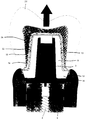
- the drawing shows an axial longitudinal section of an abutment 2 which is fastened on an implant body 6 by means of a screw 4.
- a fully ceramic male or primary crown 8 is firmly connected to the abutment 2.
- the surface 10 of the primary crown 8 is highly polished.
- a grinding wheel is expediently used, which is preferably glued with corundum paper. This manufacturing step ensures an exact and highly polished outer contour of the all-ceramic primary crown.
- the surface 10 of the primary crown 8 is conical, the cone angle being predefined in accordance with the requirements.
- the surface 10 of the primary crown 8 can be cylindrical in the context of the invention. To machine the primary crown, it is fixed in a clamping device with the help of its press channel.
- the primary crown 8 is adhesively attached to the metal abutment 2. Conventional milling devices can also be used to process the ceramic surface, with a roller covered with sandpaper being clamped.
- the thin-walled, all-ceramic primary crown which is individually intended for a natural tooth, is highly fragile until it is finally cemented in the mouth, and a viscous cementation composite can lead to breakage of the crown if it is forced too far.
- a galvanic cap is therefore placed on the primary cap during the adhesive attachment during manufacture. The displacement of the fastening composite creates tensile stresses in the ceramic, which, however, are expediently transferred to the form-fitting galvanic cap and are therefore reduced.
- the primary crown 8 also advantageously contains a step 14 with an enlarged outer diameter in the area of the gingiva 12. This creates sufficient cervical space for veneering the secondary structure.
- the holding element also contains a die or secondary crown 16 which is connected to a frame 18 of the removable denture and which is preferably designed as a cap.
- the framework 18 also carries a veneer 20 in a known manner.
- the secondary crown is made from dental alloys, electroformed gold or pure titanium. If the secondary crown consists of fine gold, the joining gap 24 has a width of the order of 5 ⁇ m.
- the secondary crown 16 is produced by directly electroplating fine gold onto the primary crown 8.
- the outer contour of the all-ceramic primary crown 8 is preferably provided with a layer of conductive material, in particular silver conductive lacquer.
- the galvanization of the secondary crown is subsequently carried out in a further process step. This creates a fine gold cap, which has a layer thickness of 0.1 to 0.2 mm. The layer thickness is specified by specifying the electroplating time and current strength as required.
- This galvanic cap is subsequently separated from the primary crown, the conductive material, in particular the conductive silver varnish, being expediently removed by briefly acting with high-percentage nitric acid.
- direct electroplating onto the standardized and industrially prefabricated primary crown ensures a considerable simplification of the manufacturing process and high precision.
- connection of the secondary crown 16 to the framework 18, in particular of pure titanium or Cr-Co-Mo, takes place intraorally in a particularly expedient manner via an adhesive connection.
- This joining technique guarantees an absolutely passive fit of the prosthesis, especially with several implant pillars.
- the framework 18 is finished with conventional prosthetic and veneering resin.
- the glued-in galvanic caps or secondary crowns 16 are thereby given an additional marginal strength, so that canting during insertion is tolerated without damage.
Landscapes
- Health & Medical Sciences (AREA)
- Oral & Maxillofacial Surgery (AREA)
- Dentistry (AREA)
- Epidemiology (AREA)
- Life Sciences & Earth Sciences (AREA)
- Animal Behavior & Ethology (AREA)
- General Health & Medical Sciences (AREA)
- Public Health (AREA)
- Veterinary Medicine (AREA)
- Orthopedic Medicine & Surgery (AREA)
- Chemical & Material Sciences (AREA)
- Engineering & Computer Science (AREA)
- Ceramic Engineering (AREA)
- Dental Prosthetics (AREA)
- Dental Preparations (AREA)
- Dental Tools And Instruments Or Auxiliary Dental Instruments (AREA)
Abstract
Description
- Die Erfindung bezieht sich auf ein Halteelement für einen herausnehmbaren Zahnersatz gemäß den im Oberbegriff des Patentanspruchs 1 angegebenen Merkmalen.
- Als Halteelemente für herausnehmbaren Zahnersatz sind heute vor allem Stege, Doppelkronen, Anker, Klammern und Magnetattachments im Einsatz. Ausgehend von einer soliden Befunderhebung müssen neben der Mundhygiene und der prothetischen Wertigkeit vorhandener Pfeilerzähne vor allem Statik, Ästhetik, Handhabung, Erweiterbarkeit und Kosten des Zahnersatzes Berücksichtigung finden. Als weitere Aspekte sind Forderungen der Patienten nach biokompatiblen Werkstoffen sowie eine sehr anspruchsvolle Ästhetik zu beachten. Ferner wird durch verbesserte Hygieneaufklärung und -kontrolle, durch einen hohen zahnärztlichen Versorgungsgrad und zunehmende Verwendung von enossalen Implantaten die Indikation für herausnehmbaren Zahnersatz in ein höheres Lebensalter verschoben. Die damit einhergehenden Probleme wie abnehmende mentale und manuelle Fähigkeiten für Hygiene und Handhabung des Zahnersatzes sowie in den Vordergrund tretende multimorbide Alterserscheinungen und Krankheiten sind hinlänglich bekannt. Auf Doppelkronen verankerter Zahnersatz hält dem modernen Anforderungsprofil bezüglich Biokompatibilität und Ästhetik noch nicht in allen Punkten Stand. Obwohl die Fügetechniken - Laserschweißen oder Kleben - korrodierende Lotlegierungen ersetzen können und biokompatible Dentallegierungen oder Reintitan für Gerüste verfügbar sind, bleiben spezifische Kompromisse beim Halteelement Doppelkrone bestehen, und es sei vor allem auf die Korrosion zwischen Matrize und Patrize, das Haftverhalten und die sichtbaren Metallränder von Primärkronen hingewiesen.
- Der Platzbedarf verblendeter Sekundärkronen erfordert einen hohen Hartsubstanzabtrag bei natürlichen Pfeilern. Sind zusätzlich noch größere Korrekturen bei einer unterschiedlichen Einschubrichtung der Pfeilerzähne vorzunehmen, so entsteht ein Zielkonflikt zwischen der Ästhetik des Zahnersatzes und der Vitalerhaltung des Zahnes. Ferner ist ein sichtbarer Metallrand der Primärkrone unvermeidlich, wenn aufgrund eines subgingivalen Präparationsrandes eine leichte Retraktion der Gingiva auftritt. Aus parodontalprophylaktischen Gründen kann die Primärkrone von der Sekundärkrone nur bis zum äquigingivalen Niveau erfaßt und verdeckt werden. Auch empfinden Patienten ein entstellendes Aussehen nach Herausnahme des Zahnersatzes, insbesondere aufgrund sichtbarer metallfarbener Primärkronen. Die Funktionalität von Doppelkronensystemen hängt stark von der manuellen Fertigungsqualität ab und erfordert erfahrene und hochqualifizierte Zahntechniker. Im Gegensatz zu konfektionierten Halteelementen ist keine reproduzierbare und exakte Einstellung der Friktion zwischen Primär- und Sekundärkrone möglich. Klinische Erfahrungen zeigen ein nicht konstantes Haftverhalten nach mehrjähriger Tragedauer oder nach Verschleißversuchen sowohl bei parallelwandigen Teleskopen als auch bei Konuskronen. Einerseits führen Verschleißerscheinungen zu abnehmender Friktion, welche schlecht oder überhaupt nicht verbessert werden kann. Andererseits kann auch das umgekehrte Verhalten eintreten, wenn hohe Kaukräfte große Flächen zwischen Primär- und Sekundärkrone kaltverschweißen. Kaltverschweißte Legierungsgefüge trennen sich meist nicht an der Stelle, wo sie gebunden wurden. Dies führt zu einer Zerrüttung und Aufrauhung der Fügeflächen und somit zu einer Friktionszunahme. Derartige Prothesen haften so fest, daß sie beim Herausnehmen das Parodont unphysiologisch belasten oder vom Patienten nicht mehr selbst herausgenommmen werden können. Des weiteren wirkt Speichel im Fügespalt als korrosives Medium zwischen den metallischen Oberflächen. Fast alle heutigen Implantatsysteme bieten Abutments aus Reintitan an. Falls Primärkrone und/oder Sekundärkrone nicht ebenfalls aus Reintitan bestehen, können im Spalt zwischen Matrize und Patrize Korrosionserscheinungen auftreten. Auf diese stark eingeschränkte Biokompatibilität reagiert besonders das perimplantäre Weichgewebe empfindlich, weil es aus qualitativ minderwertigem Narbengewebe besteht. Ein passiver Sitz von weitspannigen Grüsten mit Doppelkronen stellt an die Präzision eine Herausforderung dar, welche mit anspruchsvollen und zeitintensiven Zahntechischen und klinischen Arbeitsschritten verbunden ist.
- Vor allem in der Implantatprothetik können kleine Imperfektionen eines weitspannig verblockten Gerüst nicht kompensiert werden, weil die ankylotische Osseointegration kaum Auslenkungen der Implantatpfeiler zuläßt - im Gegensatz zur parodontalen Lagerung natürlicher Zähne. Es verursacht Belastungsspitzen an den enossalen Implantatkörpern, die zu Knochenresorptionen führen können. Die Prozedur einer Gerüsttrennung, intraoralen Fixierung und erneutem Fügen im Labor tritt daher häufiger auf als bei zahngestützten Teilprothesen. Die o.g. Unzugänglichkeiten sind unter anderem auf die Interaktion und Kombination der metallischen Oberflächen von Doppelkronen zurückzuführen.
- Hiervon ausgehend liegt der Erfindung die Aufgabe zugrunde, die aufgezeigten Schwierigkeiten bei einm Halteelement der genannten Art mit geringem Aufwand zu beseitigen. Das Halteelement soll einen geringen Fertigungsaufwand erfordern und eine hohe Verschleißfestigkeit und eine weitgehend konstante Haftkraft zwischen den Anlageflächen oder korrespondierenden Oberflächen der Doppelkronen sollen sichergestellt sein.
- Die Lösung dieser Aufgabe erfolgt gemäß den kennzeichnenden Merkmalen des Patentanspruchs 1.
- Das erfindungsgemäße Halteelement zeichnet sich durch eine funktionsgerechte Konstruktion aus und ermöglicht mit geringem Fertigungsaufwand die Vorgabe einer zumindest näherungsweise konstanten Haltekraft für den Zahnersatz. Die Primärkrone besteht zumindest im Bereich der Anlageflächen aus Keramik, und die Gewebefreundlichkeit, Härte, Korrosionsbeständigkeit und Farbe der Dentalkeramik werden in vorteilhafter Weise genutzt. Die vollkeramische Primärkrone dient als zylindrisch parallelwandige oder konische Patrize und die hochglanzpolierte Keramikoberfläche zeigt eine hohe Biokompatibilität gegenüber dem periimplantären Weichgewebe und geringe Plaqueaffinität. Die Primärkrone ist auf dem Zahn oder einem Implantatattachment adhäsiv befestigt, wobei als Befestigungsmittel insbesondere Klebemittel oder Zement zur Verwendung kommen. Da das Verbundverfahren bei Raumtemperatur durchgeführt wird, werden Dimensions- oder Strukturveränderungen nicht konditionierter Werkstoffregionen vermieden, wie es beispielsweise beim Aufbrennen von Keramik auf Titan zu beachten ist. Der Verbund kann in zweckmäßiger Weise standardisiert und industriell durchgeführt werden. Durch die industrielle Fertigung der keramischen Primärkrone wird zudem nicht nur eine hohe Präzision gewährleistet, sondern es werden erhebliche Fertigungsvorteile erzielt. Die vorgefertigte und standardisierte Primärkrone wird entweder auf dem Zahn oder einem Implantat befestigt.
- In zweckmäßiger Weise ist die Primärkrone als ein rotationsgesichertes Titan-Abutment eines Implantats ausgebildet und mit der vollkeramischen Oberfläche versehen. Zwischen der Keramik und dem Titan-Abutment besteht somit keine Korrosionsproblematik, wie es zwischen Dentallegierungen und Titan der Fall ist. In zweckmäßiger Weise wird der Verbund zwischen Titan-Abutment und Keramik durch konventionelle Verfahren erzielt, und zwar die Oberflächenkonditionierung des Titans mit Silicoter, Rocatec oder Kevloc-Verfahren. Die Oberflächenkonditionierung der Keramik erfolgt nach den Angaben des Herstellers, um so ein funktionssicheres Verbundkomposit zwischen Titan und Keramik zu erhalten.
- Der derart hergestellte Verbundwerkstoff zeichnet sich im Vergleich zur spröden Keramik durch eine erhöhte Lebensdauerwahrscheinlichkeit aus. In zweckmäßiger Weise wird die keramische Oberfläche der Primärkrone und insbesondere des gefertigten Titan-Keramik-Abutments vom Zahntechniker individuell geschliffen, so daß mit hoher Präzision eine gemeinsame Einschubrichtung mehrerer Halteelemente einer Prothese erzielt werden kann.
- Die Sekundärkrone und/oder Matrize besteht aus einer Dentallegierung, Reintitan oder Feingold. Die Matrize wird im zahntechnischen Labor, insbesondere automatisch aus Feingold, im Galvanisierungsautomaten gefertigt. Das Feingold wird hierbei direkt auf die keramische Oberfläche aufgebracht und vorzugsweise aufgalvanisiert. Das direkte Aufgalvanisieren gewährleistet eine hohe Passungspräzision zwischen Matrize und Patrize. Durch diese Passungspräzision und die Materialpaarung Keramik/Feingold ist ein tribologisches System geschaffen, welches eine hohe Verschleißfestigkeit und eine konstante Haftkraft zwischen Matrize und Patrize aufweist. Darüber hinaus ist hervorzuheben, daß die Haftkraft und die Passungspräzision der Matrize praktisch unabhängig ist von der manuellen Fertigkeit des Zahntechnikers. Des weiteren werden in besonders zweckmäßiger Weise die Matrizen intraoral in das Prothesengerüst eingeklebt, so daß ein hochpräziser und spannungsfreier Sitz der Prothese auf mehreren Halteelementen gewährleistet wird.
- Als zusätzliche Haftkomponente wirkt in besonders zweckmäßiger Weise im Fügespalt zwischen der Primär- und Sekundärkrone der Speichelfilm, wobei praktisch unabhängig von den verwendeten Werkstoffen ein tribologisches System definiert ist. Beim Trennen der Matrize von der Patrize entsteht ein Unterdruck, welcher über kapillare Spalträume ausgeglichen wird. Die von der Spaltbreite abhängigen Strömungswiderstände wirken einer Trennung der beiden Kronen entgegen. Weiterhin wirkt die Adhäsion des Speichelfilms. Bei direkt aufgalvanisierten Feingoldmatrizen beträgt die Schichtstärke des Speichelfilm im Fügespalt ubiquitär nur noch ca. 5 µm. Diese sehr kleine Spaltfuge vergrößert in vorteilhafter Weise die physikalischen Phänomene des kapillaren Strömungswiderstandes und der Adhäsionswirkung der Speichelflüssigkeit. Der Speichel fungiert zusätzlich als Schmiermittel im tribologischen System. Durch die geringe Oberflächenrauhigkeit der Keramik wirkt das Feingold zusätzlich als Festkörper-Schmiermittel. Eine frikative mechanische Reibung zwischen den Oberflächen der Keramikpatrize und dem Feingoldmatrize kann somit völlig vernachlässigt werden. Mit dem erfindungsgemäßen Halteelement wird in besonders zweckmäßiger Weise der erläuterte Haltemechanismus durch die perfekte Passung der direkt aufgalvanisierten Matrize in Kombination mit den Materialeigenschaften von Feingold gewährleistet. Eine diffizile Einstellung der Friktion durch den Zahntechniker ist somit nicht erforderlich.
- Das erfindungsgemäß vorgeschlagene Halteelement für einen herausnehmbaren Zahnersatz gewährleistet eine geringe Plaqueretention, einfache Handhabung für den Patienten, gleichbleibende Abzugskräfte, Verschleißfreiheit, Biokompatibilität und geringen zahntechnischen sowie klinischen Arbeitsaufwand. Die Primärkrone aus Vollkeramik ist auf Zähnen oder Implantatabutments adhäsiv befestigt oder ist bereits industriell auf das Abutment aufgebracht. Die Sekundärkrone wird konventionell aus Dentallegierungen, galvanogeformtem Gold oder Reintitan gefertigt. Durch die vollkeramische Primärkrone wird ein Kaltverschweißen mit der metallischen Sekundärkrone verhindert. Selbst hohe Kaukräfte führen bei Ausbildung der Sekundärkrone aus Feingold nicht zu einem Ansteigen der Abzugskraft für das Herausnehmen der Teilprothese. Des weiteren wird Korrosion im Fügespalt vermieden. Die ausgezeichnete Gewebefreundlichkeit und geringe Plaqueaffinität von Dentalkeramiken ermöglichen dauerhaft gesunde parodontale bzw. perimplantäre Verhältnisse. Die nach Prothesenentnahme auftretende Demaskierung des Patienten wird durch die zahnfarbenen Primärkronen aus Keramik gemildert.
- Besonders günstige klinische Ergebnisse werden mit Sekundärkappen aus galvanogeformten Feingold erzielt, welche direkt auf die polierte keramische Oberfläche galvanisiert und anschließend in das Prothesengerüst eingeklebt werden. Aufgrund der hohen Paßgenauigkeit resultiert ein extrem dünner Speichelfilm zwischen Keramik und Feingold, wodurch ein tribologisches System mit hoher Verschleißfestigkeit geschaffen ist. Die Trennung beider Kronen beruht im wesentlichen auf dem Reißen des Speichelfilms und eine diffizile Einstellung der Friktion zwischen den Kronen ist nicht erforderlich.
- Weiterbildungen und besondere Ausgestaltungen der Erfindung sind in den Unteransprüchen angegeben.
- Die Erfindung wird anhand des in der Zeichnung dargestellten besonderen Ausführungsbeispiels näher erläutert, ohne daß insoweit eine Beschränkung der Erfindung erfolgt.
- Die Zeichnung zeigt in einem axialen Längsschnitt ein Abutment 2, welches mittels einer Schraube 4 auf einem Implantatkörper 6 befestigt ist. Mit dem Abutment 2 ist eine vollkeramische Patrize oder Primärkrone 8 fest verbunden. Die Oberfläche 10 der Primärkrone 8 ist hochglanzpoliert. Zur Herstellung der hochglanzpolierten Oberfläche gelangt in zweckmäßiger Weise eine Schleifscheibe zum Einsatz, welche bevorzugt mit Korundpapier beklebt ist. Aufgrund dieses Herstellungsschritts wird eine exakte und hochglanzpolierte Außenkontur der vollkeramischen Primärkrone gewährleistet. Bei dem hier dargestellten Ausführungsbeispiel ist die Oberfläche 10 der Primärkrone 8 konisch ausgebildet, wobei der Konuswinkel den Erfordernissen entsprechend vorgegeben ist. Des weiteren kann im Rahmen der Erfindung die Oberfläche 10 der Primärkrone 8 zylindrisch ausgebildet sein. Zur Bearbeitung der Primärkrone wird diese mit Hilfe ihres Preßkanals in einer Spannvorrichtung fixiert. Die Primärkrone 8 ist auf dem Metallabutment 2 adhäsiv befestigt. Zur Bearbeitung der Keramikoberfläche können ferner konventionelle Fräsgeräte zum Einsatz gelangen, wobei eine mit Schleifpapier belegte Walze eingespannt wird.
- Die dünnwandige vollkeramische Primärkrone, welche individuell für einen natürlichen Zahn vorgesehen ist, weist bis zur endgültigen adhäsiven Befestigung im Munde eine hohe Fragilität auf, und ein viskoses Befestigungskomposit kann bei einem zu forcierten Plazieren zum Bruch der Krone führen. Zur Vermeidung dieses Nachteils wird daher bei der Herstellung eine Galvanokappe auf die Primärkappe während der adhäsiven Befestigung aufgesetzt. Das Verdrängen des Befestigungskomposits erzeugt zwar in der Keramik Zugspannungen, welche jedoch in zweckmäßiger Weise auf die formschlüssig fassende Galvanokappe übertragen und somit abgebaut werden.
- Die Primärkrone 8 enthält ferner im Bereich der Gingiva 12 in zweckmäßiger Weise eine Stufe 14 mit vergrößertem Außendurchmesser. Hierdurch ist ausreichend zervikaler Platz für die Verblendung der Sekundärstruktur geschaffen.
- Das Halteelement enthält ferner eine Matrize oder Sekundärkrone 16, welche mit einem Gerüst 18 des herausnehmbaren Zahnersatzes verbunden und welche vorzugsweise als Kappe ausgebildet ist. Das Gerüst 18 trägt in bekannter Weise ferner eine Verblendung 20. Zwischen der inneren Oberfläche 22 der Sekundärkrone 16 und der äußeren Oberfläche 10 der Primärkrone ist ein Fügespalt 24 vorhanden, welcher aufgrund der Kapillarwirkung in der Mundhöhle mit Speichel ausgefüllt ist. Erfindungsgemäß ist die Sekundärkrone aus Dentallegierungen, galvanogeformtem Gold oder Reintitan hergestellt. Sofern die Sekundärkrone aus Feingold besteht, weist der Fügespalt 24 eine Breite in der Größenordnung von 5 µm auf.
- In besonders zweckmäßiger Weise ist die Sekundärkrone 16 durch direktes Aufgalvanisieren von Feingold auf die Primärkrone 8 hergestellt. Hierzu wird die Außenkontur der vollkeramischen Primärkrone 8 vorzugsweise mit einer Lage aus leitfähigem Material, insbesondere Silberleitlack, versehen. Nachfolgend wird in einem weiteren Verfahrensschritt die Galvanisierung der Sekundärkrone durchgeführt. Es entsteht hierbei eine Feingoldkappe, welche eine Schichtstärke von 0,1 bis 0,2 mm aufweist. Die Schichtstärke wird durch Vorgabe der Galvanisierungszeit und Stromstärke den Erfordernissen entsprechend vorgegeben. Nachfolgend wird diese Galvanokappe von der Primärkrone getrennt, wobei in zweckmäßiger Weise das leitfähige Material, insbesondere der Silberleitlack, durch kurzes Einwirken hochprozentiger Salpetersäure entfernt wird. Die derart durch ein galvanisches Verfahren hergestellte, als Galvanokappe ausgebildete Sekundärkrone gewährleistet eine optimale Passung bezüglich der Primärkrone 8. Im Unterschied zu einem Replikaverfahren wird durch das direkte Aufgalvanisieren auf die standardisierte und industriell vorgefertigte Primärkrone eine erhebliche Vereinfachung des Herstellverfahrens sowie eine hohe Präzision gewährleistet.
- Die Verbindung der Sekundärkrone 16 mit dem Gerüst 18, insbesondere aus Reintitan oder Cr-Co-Mo, erfolgt in besonders zweckmäßiger Weise intraoral über eine Klebeverbindung. Durch diese Fügetechnik ist ein absolut passiver Sitz der Prothese, insbesondere bei mehreren Implantatpfeilern, gewährleistet. Es sei festgehalten, daß nach einer Kieferrelationsbestimmung und einer Funktionsabformung das Gerüst 18 mit konventionellen Prothesen- und Verblendungskunststoff fertiggestellt wird. Die eingeklebten Galvanokappen bzw. Sekundärkronen 16 erhalten hierdurch eine zusätzliche marginale Festigkeit, so daß auch Verkantungen beim Einsetzen unbeschadet toleriert werden.
-
- 2
- Abutment
- 4
- Schraube
- 6
- Implantatkörper
- 8
- Primärkrone / Patrize
- 10
- Oberfläche von 8
- 12
- Gingiva
- 14
- Stufe
- 16
- Sekundärkrone / Matrize
- 18
- Gerüst
- 20
- Verblendung
- 22
- Oberfläche
- 24
- Fügespalt
Claims (8)
- Halteelement für herausnehmbaren Zahnersatz, enthaltend eine mit dem Kiefer fest verbindbare Primärkrone (8) und eine Von dieser lösbare Sekundärkrone (16), welche mit dem Zahnersatz fest verbindbar ist,
dadurch gekennzeichnet,daß die Primärkrone (8) aus Vollkeramik besteht,daß die Sekundärkrone (16) aus einer Dentallegierung, Reintitan oder direkt aufgebrachtem Feingold besteht, wobei die Primärkrone (8) und die Sekundärkrone (16) miteinander korrespondierende konische oder zylindrische Oberflächen (10, 22) aufweisen,und daß die Primärkrone (8) auf dem Zahn oder einem Implantatabutment (2) adhäsiv befestigt ist. - Halteelement nach Anspruch 1, dadurch gekennzeichnet, daß die Primärkrone (8) eine Stufe (14) aufweist, welche im Bereich der Gingiva (12) angeordnet ist.
- Halteelement nach Anspruch 1 oder 2, dadurch gekennzeichnet, daß die Oberfläche (10) der Primärkrone (8) poliert, insbesondere hochglanzpoliert, ausgebildet ist.
- Halteelement nach einem der Ansprüche 1 bis 3, dadurch gekennzeichnet, daß die Primärkrone (8) und/oder deren Verbindung mit dem Abutment (2) und/oder die Sekundärkrone (16) industriell vorgefertigt sind.
- Halteelement nach einem der Ansprüche 1 bis 4, dadurch gekennzeichnet, daß die Sekundärkrone (16) durch direktes Galvanisieren auf die Oberfläche (10) der Primärkrone (8) hergestellt ist.
- Halteelement nach Anspruch 5, dadurch gekennzeichnet, daß die Primärkrone (8) vor dem Aufgalvanisieren mit einer entfernbaren Schicht versehen ist.
- Halteelement nach einem der Ansprüche 1 bis 6, dadurch gekennzeichnet, daß die Sekundärkrone (16), welche vorzugsweise als Galvanokappe ausgebildet ist, eine Schichtstärke zwischen 0,1 bis 0,2 mm aufweist.
- Halteelement nach einem der Ansprüche 1 bis 7, dadurch gekennzeichnet, daß die Sekundärkrone (16) intraoral mit einem Gerüst (18) des Zahnersatzes, insbesondere über eine Klebeverbindung, verbunden ist.
Applications Claiming Priority (2)
| Application Number | Priority Date | Filing Date | Title |
|---|---|---|---|
| DE19616618A DE19616618A1 (de) | 1996-04-25 | 1996-04-25 | Halteelement für einen herausnehmbaren Zahnersatz |
| DE19616618 | 1996-04-25 |
Publications (3)
| Publication Number | Publication Date |
|---|---|
| EP0803232A2 true EP0803232A2 (de) | 1997-10-29 |
| EP0803232A3 EP0803232A3 (de) | 1998-04-08 |
| EP0803232B1 EP0803232B1 (de) | 2002-07-31 |
Family
ID=7792466
Family Applications (1)
| Application Number | Title | Priority Date | Filing Date |
|---|---|---|---|
| EP97105901A Expired - Lifetime EP0803232B1 (de) | 1996-04-25 | 1997-04-10 | Halteelement für einen herausnehmbaren Zahnersatz |
Country Status (3)
| Country | Link |
|---|---|
| EP (1) | EP0803232B1 (de) |
| AT (1) | ATE221345T1 (de) |
| DE (2) | DE19616618A1 (de) |
Cited By (4)
| Publication number | Priority date | Publication date | Assignee | Title |
|---|---|---|---|---|
| EP1044658A1 (de) * | 1999-03-05 | 2000-10-18 | Hawe Neos Dental Dr. H. v. Weissenfluh SA | Matrize |
| EP1607063A1 (de) * | 2004-06-17 | 2005-12-21 | Unor AG (Unor SA) (Unor Ltd) | Abnehmbare Zahnprothesen-Verbindung |
| WO2007019386A1 (en) * | 2005-08-03 | 2007-02-15 | Provisional Implant Technology, Llc | Provisional crown for dental implants |
| US9770218B2 (en) | 2015-04-20 | 2017-09-26 | Provisional Implant Technology, Llc | Method of making a radiographic guide and a surgical stent/guide for dental implants |
Families Citing this family (4)
| Publication number | Priority date | Publication date | Assignee | Title |
|---|---|---|---|---|
| CH694571A5 (de) † | 1999-06-21 | 2005-04-15 | Dcs Forschungs & Entwicklungs | Verfahren zur Herstellung eines Zahnersatzes und eines Zahnersatzteiles, Material für ein Zahnersatzteil und Zahnersatzteil. |
| DE20304649U1 (de) | 2003-03-21 | 2003-06-12 | Siladent-Technik GmbH, 38644 Goslar | Zahnprothetische Anordnung |
| USD733886S1 (en) | 2013-11-01 | 2015-07-07 | Provisional Implant Technology, Llc | Provisional dental implant |
| USD734465S1 (en) | 2013-11-01 | 2015-07-14 | Provisional Implant Technology Llc | Provisional dental implant |
Family Cites Families (5)
| Publication number | Priority date | Publication date | Assignee | Title |
|---|---|---|---|---|
| DE3839837A1 (de) * | 1988-11-25 | 1990-05-31 | Lauks Nikola | Vorrichtung zur befestigung eines zahnersatzes an einem menschlichen kiefer |
| DE3840399C2 (de) * | 1988-11-30 | 1997-12-18 | Hornig Wolfgang | Verfahren zur Herstellung von metallischen Zahnersatzteilen |
| DE4015008A1 (de) * | 1990-05-10 | 1991-11-14 | Koerber Karlheinz | Konus-doppelhuelse zur verankerung von zahnersatz |
| DE4017838C1 (en) * | 1990-06-02 | 1991-12-12 | Abc-Zahntechnik Bienenstein + Soehne Gmbh, 5354 Weilerswist, De | Fastener for releasable dental prosthesis - has rotary moulded with external thread, or peripheral grooving, rigidly fixed in secondary part bore |
| DE9100081U1 (de) * | 1991-01-05 | 1991-03-28 | Wall, Giselher, Dr., 8730 Bad Kissingen | Zahntechnisch-prothetische Halbpassungen als Schichtkörper mit korrosionswidriger Oberflächenausrüstung der Funktionsflächen |
-
1996
- 1996-04-25 DE DE19616618A patent/DE19616618A1/de not_active Ceased
-
1997
- 1997-04-10 DE DE59707831T patent/DE59707831D1/de not_active Expired - Lifetime
- 1997-04-10 AT AT97105901T patent/ATE221345T1/de not_active IP Right Cessation
- 1997-04-10 EP EP97105901A patent/EP0803232B1/de not_active Expired - Lifetime
Cited By (4)
| Publication number | Priority date | Publication date | Assignee | Title |
|---|---|---|---|---|
| EP1044658A1 (de) * | 1999-03-05 | 2000-10-18 | Hawe Neos Dental Dr. H. v. Weissenfluh SA | Matrize |
| EP1607063A1 (de) * | 2004-06-17 | 2005-12-21 | Unor AG (Unor SA) (Unor Ltd) | Abnehmbare Zahnprothesen-Verbindung |
| WO2007019386A1 (en) * | 2005-08-03 | 2007-02-15 | Provisional Implant Technology, Llc | Provisional crown for dental implants |
| US9770218B2 (en) | 2015-04-20 | 2017-09-26 | Provisional Implant Technology, Llc | Method of making a radiographic guide and a surgical stent/guide for dental implants |
Also Published As
| Publication number | Publication date |
|---|---|
| DE59707831D1 (de) | 2002-09-05 |
| EP0803232B1 (de) | 2002-07-31 |
| DE19616618A1 (de) | 1997-11-06 |
| ATE221345T1 (de) | 2002-08-15 |
| EP0803232A3 (de) | 1998-04-08 |
Similar Documents
| Publication | Publication Date | Title |
|---|---|---|
| DE102004027959B4 (de) | Zahnimplantat und Verfahren zu dessen Herstellung | |
| EP1450722B2 (de) | Keramisches dentalimplantat | |
| DE102012201092B4 (de) | Zahntechnisches Implantatsystem | |
| EP0319717B1 (de) | Wurzelstift | |
| CH694571A5 (de) | Verfahren zur Herstellung eines Zahnersatzes und eines Zahnersatzteiles, Material für ein Zahnersatzteil und Zahnersatzteil. | |
| DE102012108153A1 (de) | Rohling und Verfahren zur Herstellung einer Dentalrestauration durch substraktive Bearbeitung | |
| EP0803232B1 (de) | Halteelement für einen herausnehmbaren Zahnersatz | |
| EP0842643B1 (de) | Zweiteiliges dentales Implantat mit aufgalvanisierter Metallschicht | |
| EP2742905B1 (de) | Dentalimplantat | |
| DE202007019234U1 (de) | Verbindungselement für abnehmbare Zahnprothese | |
| DE202008007189U1 (de) | Abutment für ein Schraubimplantat in einem Kieferknochen | |
| EP0870478A1 (de) | Dentalretentionselement aus hochfester Keramik | |
| EP0898943B1 (de) | Dentalprothetikteil | |
| DE102007025164A1 (de) | Verfahren und Vorrichtungen zum Erstellen eines Modells eines Patientengebisses | |
| DE19835778A1 (de) | Verankerung für herausnehmbaren Zahnersatz an Kronen oder Brücken | |
| DE3535266A1 (de) | Dentale verankerung | |
| DE19956424B4 (de) | Zahntechnische Horizontalschraube | |
| DE4120132C2 (de) | Zahnersatz | |
| DE10337462B4 (de) | Verbindungsvorrichtung | |
| DE102004043200B4 (de) | Zahnprothese zum Einsetzen im Bereich einer Zahnlücke | |
| EP0664106A2 (de) | System zur Restauration zerstörter Zähne | |
| DE19624864C2 (de) | Restaurationsstift | |
| DE19526523C1 (de) | Implantat für den Zahnwurzelersatz aus Glaskeramik, faserverstärktem Kohlenstoff oder Titan und Zahnfachabformwerkzeug hierzu | |
| EP4082476A1 (de) | Dentales implantatsystem | |
| DE19754256A1 (de) | Implantatgestützte Zahnprothese und Verfahren zu ihrer Herstellung |
Legal Events
| Date | Code | Title | Description |
|---|---|---|---|
| PUAI | Public reference made under article 153(3) epc to a published international application that has entered the european phase |
Free format text: ORIGINAL CODE: 0009012 |
|
| AK | Designated contracting states |
Kind code of ref document: A2 Designated state(s): AT BE CH DE DK ES FR GB IT LI NL SE |
|
| PUAL | Search report despatched |
Free format text: ORIGINAL CODE: 0009013 |
|
| AK | Designated contracting states |
Kind code of ref document: A3 Designated state(s): AT BE CH DE DK ES FR GB IT LI NL SE |
|
| RAP1 | Party data changed (applicant data changed or rights of an application transferred) |
Owner name: FRIATEC AKTIENGESELLSCHAFT |
|
| RHK1 | Main classification (correction) |
Ipc: A61C 5/08 |
|
| 17P | Request for examination filed |
Effective date: 19980430 |
|
| RAP1 | Party data changed (applicant data changed or rights of an application transferred) |
Owner name: FRIADENT GMBH |
|
| GRAG | Despatch of communication of intention to grant |
Free format text: ORIGINAL CODE: EPIDOS AGRA |
|
| 17Q | First examination report despatched |
Effective date: 20010928 |
|
| GRAG | Despatch of communication of intention to grant |
Free format text: ORIGINAL CODE: EPIDOS AGRA |
|
| GRAG | Despatch of communication of intention to grant |
Free format text: ORIGINAL CODE: EPIDOS AGRA |
|
| GRAH | Despatch of communication of intention to grant a patent |
Free format text: ORIGINAL CODE: EPIDOS IGRA |
|
| GRAH | Despatch of communication of intention to grant a patent |
Free format text: ORIGINAL CODE: EPIDOS IGRA |
|
| GRAA | (expected) grant |
Free format text: ORIGINAL CODE: 0009210 |
|
| AK | Designated contracting states |
Kind code of ref document: B1 Designated state(s): AT BE CH DE DK ES FR GB IT LI NL SE |
|
| PG25 | Lapsed in a contracting state [announced via postgrant information from national office to epo] |
Ref country code: NL Free format text: LAPSE BECAUSE OF FAILURE TO SUBMIT A TRANSLATION OF THE DESCRIPTION OR TO PAY THE FEE WITHIN THE PRESCRIBED TIME-LIMIT Effective date: 20020731 |
|
| REF | Corresponds to: |
Ref document number: 221345 Country of ref document: AT Date of ref document: 20020815 Kind code of ref document: T |
|
| REG | Reference to a national code |
Ref country code: GB Ref legal event code: FG4D Free format text: NOT ENGLISH Ref country code: CH Ref legal event code: EP |
|
| GBT | Gb: translation of ep patent filed (gb section 77(6)(a)/1977) |
Effective date: 20020731 |
|
| REF | Corresponds to: |
Ref document number: 59707831 Country of ref document: DE Date of ref document: 20020905 |
|
| PG25 | Lapsed in a contracting state [announced via postgrant information from national office to epo] |
Ref country code: SE Free format text: LAPSE BECAUSE OF FAILURE TO SUBMIT A TRANSLATION OF THE DESCRIPTION OR TO PAY THE FEE WITHIN THE PRESCRIBED TIME-LIMIT Effective date: 20021031 Ref country code: DK Free format text: LAPSE BECAUSE OF FAILURE TO SUBMIT A TRANSLATION OF THE DESCRIPTION OR TO PAY THE FEE WITHIN THE PRESCRIBED TIME-LIMIT Effective date: 20021031 |
|
| ET | Fr: translation filed | ||
| NLV1 | Nl: lapsed or annulled due to failure to fulfill the requirements of art. 29p and 29m of the patents act | ||
| PG25 | Lapsed in a contracting state [announced via postgrant information from national office to epo] |
Ref country code: ES Free format text: LAPSE BECAUSE OF FAILURE TO SUBMIT A TRANSLATION OF THE DESCRIPTION OR TO PAY THE FEE WITHIN THE PRESCRIBED TIME-LIMIT Effective date: 20030130 |
|
| PLBE | No opposition filed within time limit |
Free format text: ORIGINAL CODE: 0009261 |
|
| STAA | Information on the status of an ep patent application or granted ep patent |
Free format text: STATUS: NO OPPOSITION FILED WITHIN TIME LIMIT |
|
| 26N | No opposition filed |
Effective date: 20030506 |
|
| PGFP | Annual fee paid to national office [announced via postgrant information from national office to epo] |
Ref country code: GB Payment date: 20100324 Year of fee payment: 14 |
|
| PGFP | Annual fee paid to national office [announced via postgrant information from national office to epo] |
Ref country code: FR Payment date: 20100506 Year of fee payment: 14 |
|
| PGFP | Annual fee paid to national office [announced via postgrant information from national office to epo] |
Ref country code: IT Payment date: 20100427 Year of fee payment: 14 Ref country code: DE Payment date: 20100430 Year of fee payment: 14 Ref country code: AT Payment date: 20100422 Year of fee payment: 14 |
|
| PGFP | Annual fee paid to national office [announced via postgrant information from national office to epo] |
Ref country code: CH Payment date: 20100426 Year of fee payment: 14 Ref country code: BE Payment date: 20100423 Year of fee payment: 14 |
|
| BERE | Be: lapsed |
Owner name: *FRIADENT G.M.B.H. Effective date: 20110430 |
|
| REG | Reference to a national code |
Ref country code: DE Ref legal event code: R119 Ref document number: 59707831 Country of ref document: DE |
|
| REG | Reference to a national code |
Ref country code: DE Ref legal event code: R119 Ref document number: 59707831 Country of ref document: DE |
|
| REG | Reference to a national code |
Ref country code: CH Ref legal event code: PL |
|
| GBPC | Gb: european patent ceased through non-payment of renewal fee |
Effective date: 20110410 |
|
| REG | Reference to a national code |
Ref country code: AT Ref legal event code: MM01 Ref document number: 221345 Country of ref document: AT Kind code of ref document: T Effective date: 20110410 |
|
| REG | Reference to a national code |
Ref country code: FR Ref legal event code: ST Effective date: 20111230 |
|
| PG25 | Lapsed in a contracting state [announced via postgrant information from national office to epo] |
Ref country code: FR Free format text: LAPSE BECAUSE OF NON-PAYMENT OF DUE FEES Effective date: 20110502 Ref country code: BE Free format text: LAPSE BECAUSE OF NON-PAYMENT OF DUE FEES Effective date: 20110430 Ref country code: CH Free format text: LAPSE BECAUSE OF NON-PAYMENT OF DUE FEES Effective date: 20110430 Ref country code: LI Free format text: LAPSE BECAUSE OF NON-PAYMENT OF DUE FEES Effective date: 20110430 |
|
| PG25 | Lapsed in a contracting state [announced via postgrant information from national office to epo] |
Ref country code: GB Free format text: LAPSE BECAUSE OF NON-PAYMENT OF DUE FEES Effective date: 20110410 Ref country code: IT Free format text: LAPSE BECAUSE OF NON-PAYMENT OF DUE FEES Effective date: 20110410 Ref country code: AT Free format text: LAPSE BECAUSE OF NON-PAYMENT OF DUE FEES Effective date: 20110410 |
|
| PG25 | Lapsed in a contracting state [announced via postgrant information from national office to epo] |
Ref country code: DE Free format text: LAPSE BECAUSE OF NON-PAYMENT OF DUE FEES Effective date: 20111031 |