EP0803227B1 - Système d'imagerie à ultrasons pour le dignostic médicale comportant guide de balayage pour le sytème d'imagerie tridimensionnelle - Google Patents
Système d'imagerie à ultrasons pour le dignostic médicale comportant guide de balayage pour le sytème d'imagerie tridimensionnelle Download PDFInfo
- Publication number
- EP0803227B1 EP0803227B1 EP97302842A EP97302842A EP0803227B1 EP 0803227 B1 EP0803227 B1 EP 0803227B1 EP 97302842 A EP97302842 A EP 97302842A EP 97302842 A EP97302842 A EP 97302842A EP 0803227 B1 EP0803227 B1 EP 0803227B1
- Authority
- EP
- European Patent Office
- Prior art keywords
- scanning
- image
- imaging system
- diagnostic imaging
- dimensional
- Prior art date
- Legal status (The legal status is an assumption and is not a legal conclusion. Google has not performed a legal analysis and makes no representation as to the accuracy of the status listed.)
- Expired - Lifetime
Links
- 238000002059 diagnostic imaging Methods 0.000 title claims description 17
- 238000003384 imaging method Methods 0.000 title description 5
- 239000000523 sample Substances 0.000 claims abstract description 32
- 238000012545 processing Methods 0.000 claims description 11
- 230000000007 visual effect Effects 0.000 claims description 10
- 230000008878 coupling Effects 0.000 claims 1
- 238000010168 coupling process Methods 0.000 claims 1
- 238000005859 coupling reaction Methods 0.000 claims 1
- 238000000034 method Methods 0.000 abstract description 10
- 230000008569 process Effects 0.000 abstract description 4
- 238000002604 ultrasonography Methods 0.000 description 24
- 230000033001 locomotion Effects 0.000 description 12
- 238000009877 rendering Methods 0.000 description 7
- 210000003734 kidney Anatomy 0.000 description 4
- 210000004185 liver Anatomy 0.000 description 4
- 230000017531 blood circulation Effects 0.000 description 3
- 230000000994 depressogenic effect Effects 0.000 description 3
- 238000002592 echocardiography Methods 0.000 description 3
- 230000000717 retained effect Effects 0.000 description 3
- 238000010408 sweeping Methods 0.000 description 3
- 238000010586 diagram Methods 0.000 description 2
- 230000007246 mechanism Effects 0.000 description 2
- 210000000056 organ Anatomy 0.000 description 2
- 230000035479 physiological effects, processes and functions Effects 0.000 description 2
- 210000003484 anatomy Anatomy 0.000 description 1
- 230000015572 biosynthetic process Effects 0.000 description 1
- 230000008859 change Effects 0.000 description 1
- 238000006243 chemical reaction Methods 0.000 description 1
- 230000001427 coherent effect Effects 0.000 description 1
- 239000003086 colorant Substances 0.000 description 1
- 239000012141 concentrate Substances 0.000 description 1
- 238000010276 construction Methods 0.000 description 1
- 238000012217 deletion Methods 0.000 description 1
- 230000037430 deletion Effects 0.000 description 1
- 230000001419 dependent effect Effects 0.000 description 1
- 230000000881 depressing effect Effects 0.000 description 1
- 238000001514 detection method Methods 0.000 description 1
- 238000003745 diagnosis Methods 0.000 description 1
- 230000000694 effects Effects 0.000 description 1
- 230000006870 function Effects 0.000 description 1
- 210000003709 heart valve Anatomy 0.000 description 1
- 230000006872 improvement Effects 0.000 description 1
- 210000000936 intestine Anatomy 0.000 description 1
- 238000005259 measurement Methods 0.000 description 1
- 238000012544 monitoring process Methods 0.000 description 1
- 238000005192 partition Methods 0.000 description 1
- 238000003825 pressing Methods 0.000 description 1
- 230000029058 respiratory gaseous exchange Effects 0.000 description 1
- 230000004044 response Effects 0.000 description 1
- 239000011435 rock Substances 0.000 description 1
- 230000001629 suppression Effects 0.000 description 1
- 230000001360 synchronised effect Effects 0.000 description 1
- 238000012549 training Methods 0.000 description 1
- 230000009466 transformation Effects 0.000 description 1
- 238000009966 trimming Methods 0.000 description 1
Images


Classifications
-
- G—PHYSICS
- G01—MEASURING; TESTING
- G01S—RADIO DIRECTION-FINDING; RADIO NAVIGATION; DETERMINING DISTANCE OR VELOCITY BY USE OF RADIO WAVES; LOCATING OR PRESENCE-DETECTING BY USE OF THE REFLECTION OR RERADIATION OF RADIO WAVES; ANALOGOUS ARRANGEMENTS USING OTHER WAVES
- G01S7/00—Details of systems according to groups G01S13/00, G01S15/00, G01S17/00
- G01S7/52—Details of systems according to groups G01S13/00, G01S15/00, G01S17/00 of systems according to group G01S15/00
- G01S7/52017—Details of systems according to groups G01S13/00, G01S15/00, G01S17/00 of systems according to group G01S15/00 particularly adapted to short-range imaging
- G01S7/52023—Details of receivers
- G01S7/52034—Data rate converters
-
- B—PERFORMING OPERATIONS; TRANSPORTING
- B82—NANOTECHNOLOGY
- B82Y—SPECIFIC USES OR APPLICATIONS OF NANOSTRUCTURES; MEASUREMENT OR ANALYSIS OF NANOSTRUCTURES; MANUFACTURE OR TREATMENT OF NANOSTRUCTURES
- B82Y15/00—Nanotechnology for interacting, sensing or actuating, e.g. quantum dots as markers in protein assays or molecular motors
-
- G—PHYSICS
- G01—MEASURING; TESTING
- G01S—RADIO DIRECTION-FINDING; RADIO NAVIGATION; DETERMINING DISTANCE OR VELOCITY BY USE OF RADIO WAVES; LOCATING OR PRESENCE-DETECTING BY USE OF THE REFLECTION OR RERADIATION OF RADIO WAVES; ANALOGOUS ARRANGEMENTS USING OTHER WAVES
- G01S15/00—Systems using the reflection or reradiation of acoustic waves, e.g. sonar systems
- G01S15/88—Sonar systems specially adapted for specific applications
- G01S15/89—Sonar systems specially adapted for specific applications for mapping or imaging
- G01S15/8906—Short-range imaging systems; Acoustic microscope systems using pulse-echo techniques
- G01S15/8993—Three dimensional imaging systems
-
- G—PHYSICS
- G01—MEASURING; TESTING
- G01S—RADIO DIRECTION-FINDING; RADIO NAVIGATION; DETERMINING DISTANCE OR VELOCITY BY USE OF RADIO WAVES; LOCATING OR PRESENCE-DETECTING BY USE OF THE REFLECTION OR RERADIATION OF RADIO WAVES; ANALOGOUS ARRANGEMENTS USING OTHER WAVES
- G01S7/00—Details of systems according to groups G01S13/00, G01S15/00, G01S17/00
- G01S7/52—Details of systems according to groups G01S13/00, G01S15/00, G01S17/00 of systems according to group G01S15/00
- G01S7/52017—Details of systems according to groups G01S13/00, G01S15/00, G01S17/00 of systems according to group G01S15/00 particularly adapted to short-range imaging
- G01S7/52053—Display arrangements
- G01S7/52057—Cathode ray tube displays
- G01S7/52074—Composite displays, e.g. split-screen displays; Combination of multiple images or of images and alphanumeric tabular information
-
- G—PHYSICS
- G01—MEASURING; TESTING
- G01S—RADIO DIRECTION-FINDING; RADIO NAVIGATION; DETERMINING DISTANCE OR VELOCITY BY USE OF RADIO WAVES; LOCATING OR PRESENCE-DETECTING BY USE OF THE REFLECTION OR RERADIATION OF RADIO WAVES; ANALOGOUS ARRANGEMENTS USING OTHER WAVES
- G01S7/00—Details of systems according to groups G01S13/00, G01S15/00, G01S17/00
- G01S7/52—Details of systems according to groups G01S13/00, G01S15/00, G01S17/00 of systems according to group G01S15/00
- G01S7/52017—Details of systems according to groups G01S13/00, G01S15/00, G01S17/00 of systems according to group G01S15/00 particularly adapted to short-range imaging
- G01S7/52079—Constructional features
-
- G—PHYSICS
- G01—MEASURING; TESTING
- G01S—RADIO DIRECTION-FINDING; RADIO NAVIGATION; DETERMINING DISTANCE OR VELOCITY BY USE OF RADIO WAVES; LOCATING OR PRESENCE-DETECTING BY USE OF THE REFLECTION OR RERADIATION OF RADIO WAVES; ANALOGOUS ARRANGEMENTS USING OTHER WAVES
- G01S15/00—Systems using the reflection or reradiation of acoustic waves, e.g. sonar systems
- G01S15/88—Sonar systems specially adapted for specific applications
- G01S15/89—Sonar systems specially adapted for specific applications for mapping or imaging
- G01S15/8906—Short-range imaging systems; Acoustic microscope systems using pulse-echo techniques
- G01S15/8979—Combined Doppler and pulse-echo imaging systems
-
- Y—GENERAL TAGGING OF NEW TECHNOLOGICAL DEVELOPMENTS; GENERAL TAGGING OF CROSS-SECTIONAL TECHNOLOGIES SPANNING OVER SEVERAL SECTIONS OF THE IPC; TECHNICAL SUBJECTS COVERED BY FORMER USPC CROSS-REFERENCE ART COLLECTIONS [XRACs] AND DIGESTS
- Y10—TECHNICAL SUBJECTS COVERED BY FORMER USPC
- Y10S—TECHNICAL SUBJECTS COVERED BY FORMER USPC CROSS-REFERENCE ART COLLECTIONS [XRACs] AND DIGESTS
- Y10S128/00—Surgery
- Y10S128/916—Ultrasound 3-D imaging
Definitions
- This invention relates to medical ultrasonic diagnostic imaging systems and, in particular, to a scanning aid which facilitates ultrasonic scanning of a three dimensional region of the body.
- U.S. Patent 5,474,073 describes three dimensional imaging techniques used in the HDI® 3000 ultrasonic diagnostic imaging system, the first commercial ultrasound system with fully integrated three dimensional imaging capability.
- One attribute of the techniques described in the '073 patent is the ability to gather three dimensional image data freehand, that is, with just an ordinary ultrasonic scanhead.
- the prior art is replete with complicated, awkward, and expensive mechanisms which attach to or hold a scanhead for three dimensional scanning. While such mechanisms are often capable of providing accurate interplane spacing measurements, their bulk, complexity, inconvenience and cost usually discourage all but the most persevering researchers. What physicians desire is to be able to perform three dimensional ultrasonic scanning without the need for excessive paraphernalia.
- the HDI 3000 system provides exactly that.
- a visual and/or audible scanning guide is provided to aid the physician in ultrasonic scanning of the body for three dimensional imaging.
- the guide calibrates the physician's scanning to a desired sweep speed across the body.
- the guide also provides information as to the amount of image data which has been acquired.
- the guide is further capable of informing the physician as to the point that a sufficient quantum of image data has been gathered for three dimensional reconstruction.
- both a scanning speed reference and a measure of acquired three dimensional image data are provided simultaneously by the same guide.
- the scanning guide is a visual and/or audible indicator which is visually or audibly modulated in correspondence with desired scanning speed, and has a magnitude or duration which represents a measure of acquired three dimensional image data.
- the scanning guide may be used as a scanning training aid.
- the guide is repetitively cycled through its range of modulation, enabling the physician to immediately gauge scanning speed and duration.
- the scanning guide also provides an indicator of the point at which a sufficient amount of image data has been acquired for three dimensional reconstruction.
- the indicator signals the filling of the three dimensional image data buffer of the ultrasound system.
- the physician is given a visual representation of the acquired image data set, and is able to designate a portion or portions of the image data set which are to be excluded from the next three dimensional ultrasonic image reconstruction.
- This enables the physician to strip away planes of tissue structure and blood flow which are extraneous to the physiology which the physician is seeking to examine, and to concentrate the three dimensional image reconstruction on the region of interest in the body. For instance, suppose the physician is interested in examining a three dimensional image of the kidney, and scans the kidney from one side where it is bounded by the liver to another side where it is bounded by the intestines.
- the physician sees in the three dimensional image that the kidney is obscured by a region of the liver which was inadvertently scanned before the probe began acquiring image planes from the kidney.
- the present invention allows the physician to trim away the unwanted liver image planes in the image plane sequence to form an image sequence for construction into a three dimensional image with a view which is unimpeded by the liver. If the physician is dissatisfied with the modified three dimensional presentation, the starting data set is retained in the ultrasound system so that the physician can modify the image data set in other respects to obtain a three dimensional ultrasonic image which is most useful to the physician's diagnosis.
- the physician is also provided with a real time indicator of the progress being made during three dimensional ultrasonic image reconstruction.
- An ultrasonic probe 10 includes a transducer array 12 which transmits and receives beams of ultrasonic energy along predetermined scanline directions under control of a beamformer 16. Ultrasonic echoes received by the elements of the transducer array are formed into coherent echoes along each scanline by the beamformer.
- the scanline echoes are processed by a digital signal processor (DSP) 22.
- the DSP 22 is capable of processing the received scanlines in a number of different ways, as indicated by the partition drawn on the DSP block 20.
- the DSP 22 includes B mode processing 22, which filters and detects echo information for the formation of B mode images.
- the DSP 22 also includes Doppler processing 24, which filters and processes ensembles of scanlines to produce Doppler signal information, such as flow velocity, variance, or Doppler power. As the '073 patent points out, Doppler power images have been found to produce excellent three dimensional ultrasonic image renderings.
- the B mode or Doppler scanlines are coupled to an image memory 30 which is partitioned into two sections, an image frame memory 32 and a 3D memory 34, both of which are controlled by a memory controller 36.
- the memory controller 36 receives control signals from the DSP 22 over a control line 26 which provides the controller with information such as the start or end of a sequence of scanlines which comprise an image frame.
- the scanlines received from the DSP are either temporarily stored in the image frame memory 32 or immediately coupled over a data bus 14 to a scan converter 40.
- the scan converter 40 has two sections called a pixel space processor (PSP) 42 and a pixel conversion module (PCM) 44.
- the PSP 42 processes ultrasonic image data into ultrasound images of the desired format and line density through interpolation and coordinate transformation of the scanline data.
- the PCM includes a frame counter and a graphics processor which produces a graphic overlay for the ultrasound image that provides graphical information such as depth markers, cursors, text, and other graphical information.
- the combined image including the ultrasonic images and the graphical information may then be displayed on an image display 50.
- grayscale scanlines pass through the image frame memory 32 and are immediately scan converted by the PSP and displayed in real time.
- a "Freeze” button on the ultrasound system control panel 90 the image being displayed at that moment on the display 50 is continually displayed until the button is pressed again to return to real time display.
- the user can also press a "Loop” button on the control panel to store a sequence of image frames in the image frame memory 32. Frames are sequentially stored in the image frame memory until the user presses the Freeze button, at which time the current contents of the image frame memory are retained. The user can then step through the memory and display each frame in succession, or can replay the retained frames in a slow motion or real time Cineloop® display.
- Doppler image of motion or flow is entered into the image frame memory, is scan converted and displayed in real time.
- Doppler images of flow conditions in the body are combined or overlaid with B mode images to provide the structure of the tissue or organs in which the flow is occurring.
- An effective technique for three dimensional imaging is to use power Doppler images without B mode information, since B mode information often has the effect of cluttering the resultant 3D display.
- the ultrasound system of FIGURE 1 produces three dimensional ultrasonic images in accordance with the principles of the present invention.
- a physician preparing to form three dimensional ultrasonic images will perform a survey scan of the patient to locate the region of interest (ROI) which she desired to image in three dimensionally. This is the initial step 71 in the flowchart of FIGURE 2.
- ROI region of interest
- the physician locates the ROI, she notes the boundaries of the ROI in the 2D images on the ultrasound display and plots a path for the probe to travel across the patient's body which will sweep the image plane of the probe through the ROI from one side of the ROI to another.
- the next step is to scan through the ROI by sliding the probe 10 across the patient's body, acquiring a sequence of substantially parallel ultrasonic image planes from one side of the ROI to another. If the physician is unfamiliar with 3D ultrasonic scanning or wishes to practice scanning or wishes to gauge the scanning speed which will acquire the greatest number of image planes, or "slices", of the ROI, she can activate the scanning guide of the present invention prior to acquiring a sequence of - image slices for 3D reconstruction.
- a constructed embodiment of the present invention has a number of control buttons on the control panel 90 of the ultrasound system.
- the control buttons are connected to the central processing unit (CPU) of the ultrasound system, which issues control signals to the components of the system which will carry out the commands issued by way of the control buttons.
- the "Loop" button results in the issuance of a command to the memory controller 36 which clears the image frame memory 32 and begins to store image frames at consecutively addressed locations in the memory. The memory is cleared by resetting the address pointer of the memory 32 to the beginning of the memory. After the Loop button has been depressed the image frame memory will store sequentially received image frames until it is completely full, and will then wrap around to the starting address and continue filling the memory with received image frames. The memory 32 will continue this sequence of operation until the physician presses the "Freeze” button, which causes the CPU to issue a command to the memory controller 36 that halts the memory 32, retaining its current contents.
- An image frame memory which operates in this fashion is ideally suited for use as a Cineloop memory.
- a Cineloop memory stores a real time 2D image sequence upon command by the user, which can be recalled and examined in close detail later.
- the Cineloop sequence can be replayed in its real time speed, in slow motion or by sequentially stepping through the frame sequence to observe subtleties of tissue motion, such as heart valve performance, which are difficult to detect in real time.
- the image frame memory 32 stores a sequence of 2D image slices which are to be reconstructed to form a three dimensional ultrasonic image.
- a visual guide depicting the filling of the memory 32 is shown on the display.
- FIGURE 3 illustrates an ultrasound display which embodies the principles of the present invention.
- a box 100 is shown at the bottom of the display screen below an ultrasound image 60.
- the ultrasound image 60 is one of a sequence of power Doppler images of blood flow network 70.
- a color or grayscale bar 64 is to the left of the image and depth graphics are shown to the right of the image.
- the box 100 includes a window 104 which represents the capacity of the image frame memory 32.
- a window 104 which represents the capacity of the image frame memory 32.
- the DSP issues a signal on line 26, informing the memory controller 36 and the scan converter 40 that the current frame is complete.
- the scan converter 40 increments a frame counter in the PCM 44.
- the count of the frame counter is converted into a white bar 102 in the window 104 by the graphics processor of the PCM, which is displayed on the display screen.
- the white bar 102 moves from left to right in the window 104 in correspondence with the filling of the image frame memory 32 with image frames.
- the window 104 is completely filled with the white bar.
- the memory 32 will wrap around and begin to fill again from the starting address. To indicate this wrap around condition, the white bar remains in the window 104, but now is overwritten by a light gray bar which proceeds from left to right in the window.
- the physician freezes the memory and stops the bar motion in the window, the colors or shades of the bars in the window will tell the user whether she is in a first or subsequent pass through the memory. If the window is both white and black, the physician knows that frame storage was stopped before the memory has been filled for the first time. But if the window is both gray and white, the physician knows that the initially stored frames have been overwritten with new frames as the memory has wrapped around.
- the white bar 102 will fill the window 102 at the same speed as the image frame memory is filled with image frames.
- the time required to do so is dependent, of course, upon the memory capacity; a larger frame memory will take longer to fill than a smaller memory.
- the filling of the memory is also a function of the frame rate and characteristics of the frame itself, such as scanline density. If the physician wants the memory 32 to fill at a slower rate, for example, the frame rate can be slowed or a probe or probe aperture with fewer scanlines used.
- PRF pulse rate frequency
- the physician can vary the PRF and hence the frame rate and the rate at which the image frame memory is filled.
- the rate at which the white bar 102 fills the window 104 is affected correspondingly.
- the physician can use the guide bar 102 to familiarize herself with the scan speed best suited for 3D image acquisition.
- the physician can press the Loop button on the control panel and allow the image frame memory to fill and wrap around continuously.
- the physician can then gauge the time required for the alternating white and gray bars to fill the window. Once the physician has gauged the time to fill the memory, she can practice sliding the probe across the patient's body over the ROI in synchronism with the moving bar 102. If the physician is uncomfortable with the short time allowed by a rapidly moving bar, she can adjust one of the parameters which affects frame rate and size, as discussed above.
- the physician has mastered the simple task of sweeping the probe across the ROI in the time it takes for the bar 102 to traverse the window 104, she is ready to acquire image slices for three dimensional reconstruction.
- step 73 the physician positions the probe at one side of the ROI on the body of the patient. This is the starting location at which the first image plane of the sweep will be acquired, and the starting position from which the physician will slide or sweep the probe across the body of the patient.
- step 74 the physician presses the Loop button to clear the image frame memory, frame counter and the guide window.
- the ultrasound system responds by starting to fill the image frame memory 32 with image frames from the probe, the white bar 102 begins to move across the window 104, and the physician starts to scan by sweeping the probe across the ROI.
- step 76 When the physician reaches the end of the scan she presses the Freeze button to freeze the current contents of the memory 32, as shown in step 76. If the scan has been properly synchronized, the image plane of the probe will be swept to the other side of the ROI at about the time the white bar has reached the end of its travel across the window. That is, the scan sweep is completed as the memory is almost completely full. This means that a maximal number of frames have been acquired in the sweep across the ROI. If the physician is dissatisfied with the scan, she can repeat the process starting from step 73.
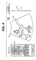
- the physician After the physician has acquired and stored a sequence of image frames, she can proceed to render a three dimensional ultrasound image. This is done by manipulating a trackball and "Select" button on the control panel 90 to pull down an image frame memory menu 66, as shown in FIGURE 4 and in step 78 of FIGURE 2.
- the menu 66 is displayed on the screen by the graphics processor of the PCM 44.
- the physician sets a number of reconstruction parameters which will govern the 3D processing of the planar image slices, as indicated by step 82 in FIGURE 2.
- the ultrasound system is controlled to render a sequence of three dimensional projection images over a sequence of different viewing angles as described in U.S. Pat. 5,485,842.
- the projection images are replayed in a real time sequence, a three dimensional rendering of the ROI appears to rotate before the viewer.
- the three dimensional presentation is rotated through an angle of ⁇ 50°.
- One parameter which the physician sets from menu 66 is the number of projection images.
- the user is allowed to select either 7, 11, or 15 projection images.
- Other numbers of projection images are possible, to the limit of the space available for projection image storage. If projection images are displayed immediately and not stored, this limitation is avoided.
- the number of images chosen is evenly distributed over the 100° angle of rotation. Thus, if eleven images are chosen, the projection images have viewing angles which vary by 9° from one projection image to the next.
- the physician uses the trackball to move a cursor (shown as an arrow) in the display to the "Images" menu push-button.
- the physician presses the Select button on the control panel to cycle the number to the right of the Images push-button to 7, 11, or 15 projection images.
- the number of projection images has been set to 15.
- a second parameter which is set in FIGURE 4 is the slice thickness.
- the slice thickness is the distance between the slice planes. If the probe is scanned slowly across the ROI the slice thickness will be thin. If the probe is scanned rapidly the slice thickness will be thick.
- a third choice in the menu 66 is a medium slice thickness.
- rendering parameters may be included in the menu. For instance, the user may be given a choice of a transparent or surface rendering, as discussed in U.S. patent application serial number 60/013,951, filed March 22, 1996*. The user may be able to choose a rendering which views the ROI from the front or the back. This change involves processing the planar image slices in reverse order, and with the x-axis reversed for each slice.
- a third parameter is a selection of the contrast for the three dimensional presentation.
- the physician selects the "Create 3D" push-button on the menu and 3D reconstruction begins, as indicated by step 84 in FIGURE 2.
- the menu 66 disappears and the projection images begin to be formed on the display screen as represented in FIGURE 5 by image 360.
- a box 110 appears below the images as the 3D reconstruction begins.
- the box 110 informs the physician of the progress of the 3D reconstruction and provides a push-button which can be selected by the physician to stop the reconstruction.
- the number of projection images and the image currently being reconstructed are shown at the right side of the box.
- a gray bar 114 responsive to the frame counter moves across the window 112 in corresponding increments: one-seventh of the window if there are seven projection images, one-eleventh of the window if there are eleven projection images, and so forth.
- the gray bar 114 has moved one eleventh of the distance across the window 112, signifying that the first of eleven projection images has been completed.
- 3D reconstruction can be performed in the scan converter 40 using the sequence of image slices stored in the image frame memory 32.
- the frame counter is incremented and the projection image is transferred over the bus 14 to a 3D memory 34 and stored.
- 3D reconstruction is complete, a sequence of projection images is stored in the 3D memory 34, each at a different viewing angle from the preceding image in the sequence.
- the sequence of 3D images which has been created and stored in the 3D memory 34 automatically begins to be displayed in sequence, and the three dimensional image of the ROI appears on the screen and begins to turn through its ⁇ 50° of rotation, as indicated by step 86 in FIGURE 2.
- the physician can select the "+Speed” and "-Speed” push-buttons to slow down or speed up the rotation of the three dimensional ROI.
- the physician may discover from viewing the three dimensional ROI that she overscanned the ROI, perhaps acquiring frames of extraneous tissue or flow before or after the desired slices of the ROI. These extraneous slices may obscure portions of the ROI which the physician would like to study.
- the extraneous slices may be removed from the reconstructed images by pulling down the menu 66 and selecting the "Trim" push-button option 128 as shown in FIGURE 6 and step 88 of FIGURE 2.
- Trim a trim box 120 appears on the screen.
- the trim box 120 includes a window 126 which, from the acquisition count of the frame counter, represents the sequence of slices acquired and used in the 3D reconstruction. When the trim box first appears, it contains two pointers 122 and 124 at each end of the window 126.
- Unwanted slices at the beginning and/or end of the sequence can be trimmed (eliminated from the 3D reconstruction) by moving the pointers in from the beginning or end of the slice sequence as shown in FIGURE 6.
- the pointers have been moved by the trackball to trim slices from both the beginning and the end of the sequence.
- the Select button is depressed to toggle from one pointer to the other, and the selected pointer is moved by manipulating the trackball control.
- the window 126 can be simply a color or shade which subjectively represents the frame sequence, or can be filled with a sequence of numbers to which the physician can move the pointer to trim at an exact frame in the sequence.
- the 3D reconstruction is repeated by selecting the Create 3D push-button again, which will reconstruct 3D images using the slice frames between the pointers 122 and 124. If the physician is dissatisfied with the new rendering, she can repeat reconstruction after resetting the pointers, or can reconstruct three dimensional images using all of the acquired image frames again as in the initial reconstruction described above.
- Flash is the detection of motion from unwanted sources, such as from respiration or other relative motion between the probe and the body, rather than the desired motion of blood flow or moving tissue. While known flash suppression techniques can usually eliminate frames containing unwanted flash, it is possible that a frame of flash artifacts may be acquired, processed and stored in the image frame memory 32. It would be desirable to omit this frame from three dimensional image reconstruction, as it would introduce undesired artifacts in the three dimensional reconstruction.
- specific frames may be deleted from three dimensional reconstruction by the use of the "Edit" push-button 130 as shown in FIGURE 7.
- the trim box 120 appears with an "X" in the window 126.
- the "X" appears in the window 126 at a location corresponding to the image frame in the image frame memory identified by the current count of the frame counter.
- the frame counter decrements or increments and the image frame 60 corresponding to the count of the counter is displayed on the screen above the trim box 120.
- the "X" in the window 126 moves to the left or the right, denoting the location of the currently displayed image in the image frame sequence.
- the physician After the physician has selected all of the image frames she wishes to delete from three dimensional reconstruction, she selects the Close push-button to terminate the Edit mode. If an "X" remains in the window 126 which has not be selected, it is deleted from the window. The physician can then select the Create 3D push-button to reconstruct three dimensional images with the omission of the "Edited" frames. If the physician is dissatisfied with the result of three dimensional reconstruction, she can re-enter the Edit mode to delete additional frames, or select displayed "X's" a second time to include previously deleted image frames in the next three dimensional reconstruction.
- FIGURE 1 shows an audio modulator 52 coupled to receive the count of the frame counter of the PCM 44.
- the audio modulator drives a speaker 54 to produce an audible tone.
- the frequency of the tone may be modulated from a low pitch to a high pitch in correspondence with the filling of the image frame memory 32.
- the duration of the tone can correspond to the time during which the frame memory is being filled.
- the audible guide enables the physician to focus her attention on the probe and its movement across the body of the patient, without the need to divert her gaze to the system display.
- the probe may be rotated about the central axis of the probe, thereby acquiring a sequence of angularly disposed image planes which intersect at a common axis, which may be used to form a 3D rendered image.
- Another alternative is to rock the probe against the body of the patient, thereby sweeping the ROI with a fan of image planes which can be reconstructed into a three dimensional wedge-shaped ROI.
- These probe motions can be performed freehand, or with the assistance of various mechanical probe or transducer arms, rockers, or rotators.
- the guide of the present invention can be utilized to assist the physician in monitoring or controlling the duration and speed of acquisition of the image plane sequence.
Landscapes
- Engineering & Computer Science (AREA)
- Physics & Mathematics (AREA)
- Radar, Positioning & Navigation (AREA)
- Remote Sensing (AREA)
- Computer Networks & Wireless Communication (AREA)
- General Physics & Mathematics (AREA)
- Acoustics & Sound (AREA)
- Chemical & Material Sciences (AREA)
- Nanotechnology (AREA)
- Health & Medical Sciences (AREA)
- Life Sciences & Earth Sciences (AREA)
- General Health & Medical Sciences (AREA)
- Molecular Biology (AREA)
- Crystallography & Structural Chemistry (AREA)
- Ultra Sonic Daignosis Equipment (AREA)
Claims (12)
- Système d'imagerie diagnostique médicale par ultrasons qui acquiert des informations d'écho ultrasonore sur une région volumétrique du corps pour une présentation en un format d'affichage tridimensionnel, comprenant :une sonde échographique pour analyser un patient afin d'acquérir des informations d'écho ultrasonore d'une région volumétrique du corps ;un dispositif de mémorisation pour mémoriser des signaux dérivés desdites informations d'écho ultrasonore ;un processeur pour traiter lesdites informations d'écho ultrasonore pour former une représentation ultrasonore tridimensionnelle de ladite région volumétrique, etun guide de balayage qui est observable par un utilisateur pour aider l'utilisateur à analyser un patient avec la sonde pendant l'acquisition d'informations d'écho d'une région volumétrique du corps.
- Système d'imagerie diagnostique médicale par ultrasons suivant la revendication 1, dans lequel ledit guide de balayage comprend un moyen pour aider l'utilisateur à déterminer le temps pendant lequel ladite région volumétrique doit être analysée.
- Système d'imagerie diagnostique médicale par ultrasons suivant la revendication 1 ou 2, dans lequel ledit guide de balayage comprend un moyen pour aider l'utilisateur à déterminer la cadence à laquelle la sonde doit être balayée par dessus ladite région volumétrique.
- Système d'imagerie diagnostique médicale par ultrasons suivant l'une quelconque des revendications 1 à 3, dans lequel ledit guide de balayage comprend un moyen pour informer l'utilisateur quant à la quantité d'informations d'écho ultrasonore qui a été acquise pendant l'analyse de ladite région volumétrique.
- Système d'imagerie diagnostique médicale par ultrasons suivant l'une quelconque des revendications 1 à 4, dans lequel ledit guide de balayage comprend un moyen pour informer l'utilisateur quand une quantité souhaitée d'informations d'écho ultrasonore a été acquise pendant l'analyse de ladite région volumétrique.
- Système d'imagerie diagnostique médicale par ultrasons suivant l'une quelconque des revendications 1 à 5, comprenant en outre un circuit pour relier ledit dispositif de mémorisation audit guide de balayage, de sorte que ledit guide de balayage fonctionne en correspondance avec le remplissage dudit dispositif de mémorisation avec des signaux dérivés desdites informations d'écho ultrasonore.
- Système d'imagerie diagnostique médicale par ultrasons suivant l'une quelconque des revendications 1 à 6, dans lequel ladite sonde échographique comprend un moyen pour acquérir des informations d'écho ultrasonore d'une région volumétrique du corps pour former des images vidéo, et dans lequel lesdites unités de mémorisation sont des images vidéo.
- Système d'imagerie diagnostique médicale par ultrasons suivant l'une quelconque des revendications 1 à 7, comprenant en outre un dispositif d'affichage, et dans lequel ledit guide de balayage comprend un indicateur visuel.
- Système d'imagerie diagnostique médicale par ultrasons suivant la revendication 8, dans lequel ledit indicateur visuel comprend un indicateur visuel mobile.
- Système d'imagerie diagnostique médicale par ultrasons suivant la revendication 9, dans lequel ledit indicateur visuel mobile comprend une barre.
- Système d'imagerie diagnostique médicale par ultrasons suivant l'une quelconque des revendications 1 à 10, dans lequel ledit processeur comprend un processeur d'image ultrasonore tridimensionnelle, réagissant à un indicateur réglable par l'utilisateur, pour former une image tridimensionnelle de ladite partie desdites images vidéo mémorisées indiquée par ledit indicateur.
- Système d'imagerie diagnostique médicale par ultrasons suivant l'une quelconque des revendications 1 à 11, comprenant en outre un compteur, relié au guide de balayage et réagissant à l'unité de mémorisation, pour compter les unités de signaux mémorisés pendant l'analyse volumétrique.
Applications Claiming Priority (2)
| Application Number | Priority Date | Filing Date | Title |
|---|---|---|---|
| US639163 | 1984-08-09 | ||
| US08/639,163 US5645066A (en) | 1996-04-26 | 1996-04-26 | Medical ultrasonic diagnostic imaging system with scanning guide for three dimensional imaging |
Publications (2)
| Publication Number | Publication Date |
|---|---|
| EP0803227A1 EP0803227A1 (fr) | 1997-10-29 |
| EP0803227B1 true EP0803227B1 (fr) | 2004-03-10 |
Family
ID=24562989
Family Applications (1)
| Application Number | Title | Priority Date | Filing Date |
|---|---|---|---|
| EP97302842A Expired - Lifetime EP0803227B1 (fr) | 1996-04-26 | 1997-04-25 | Système d'imagerie à ultrasons pour le dignostic médicale comportant guide de balayage pour le sytème d'imagerie tridimensionnelle |
Country Status (5)
| Country | Link |
|---|---|
| US (1) | US5645066A (fr) |
| EP (1) | EP0803227B1 (fr) |
| JP (1) | JPH1043182A (fr) |
| AT (1) | ATE261264T1 (fr) |
| DE (1) | DE69727994T2 (fr) |
Families Citing this family (57)
| Publication number | Priority date | Publication date | Assignee | Title |
|---|---|---|---|---|
| JPH09299368A (ja) * | 1996-05-16 | 1997-11-25 | Aloka Co Ltd | 超音波診断装置 |
| US6117080A (en) * | 1997-06-04 | 2000-09-12 | Atl Ultrasound | Ultrasonic imaging apparatus and method for breast cancer diagnosis with the use of volume rendering |
| DE19730938C1 (de) * | 1997-07-18 | 1999-03-11 | Tomtec Imaging Syst Gmbh | Verfahren und Vorrichtung zur Aufnahme von Ultraschallbildern |
| JP3352613B2 (ja) | 1997-10-17 | 2002-12-03 | 松下電器産業株式会社 | 超音波画像診断装置 |
| US6171244B1 (en) | 1997-12-31 | 2001-01-09 | Acuson Corporation | Ultrasonic system and method for storing data |
| US5971923A (en) * | 1997-12-31 | 1999-10-26 | Acuson Corporation | Ultrasound system and method for interfacing with peripherals |
| US6262749B1 (en) | 1997-12-31 | 2001-07-17 | Acuson Corporation | Ultrasonic system and method for data transfer, storage and/or processing |
| US5980461A (en) * | 1998-05-01 | 1999-11-09 | Rajan; Subramaniam D. | Ultrasound imaging apparatus for medical diagnostics |
| JP3905644B2 (ja) * | 1998-06-15 | 2007-04-18 | 東芝医用システムエンジニアリング株式会社 | 3次元超音波システム |
| JP4090576B2 (ja) * | 1998-06-17 | 2008-05-28 | フクダ電子株式会社 | 超音波診断装置 |
| JP3321103B2 (ja) * | 1998-09-04 | 2002-09-03 | ジーイー横河メディカルシステム株式会社 | 画像表示方法および超音波診断装置 |
| US6048317A (en) * | 1998-09-18 | 2000-04-11 | Hewlett-Packard Company | Method and apparatus for assisting a user in positioning an ultrasonic transducer |
| JP4260938B2 (ja) * | 1998-10-23 | 2009-04-30 | 株式会社東芝 | 3次元超音波診断装置 |
| US7756304B2 (en) * | 1998-12-30 | 2010-07-13 | Siemens Medical Solutions Usa, Inc. | Medical diagnostic ultrasonic imaging method and system for displaying multi-phase, multi-frame images |
| KR100330855B1 (ko) * | 1999-02-09 | 2002-04-03 | 이민화 | 초단수신신호의 저장과 저장된 데이터의 재사용이 가능한 디지털 초음파영상장치 |
| EP1034742A1 (fr) | 1999-03-09 | 2000-09-13 | Kreztechnik Aktiengesellschaft | Procédé pour examiner des objects avec des ultrasons |
| US6238345B1 (en) | 1999-06-30 | 2001-05-29 | Atl Ultrasound | Image memory for extended field of view ultrasonic diagnostic imaging |
| US6760486B1 (en) * | 2000-03-28 | 2004-07-06 | General Electric Company | Flash artifact suppression in two-dimensional ultrasound imaging |
| JP4619481B2 (ja) * | 2000-03-29 | 2011-01-26 | 株式会社東芝 | 超音波画像診断装置 |
| KR100388407B1 (ko) * | 2001-04-27 | 2003-06-25 | 주식회사 메디슨 | 표시 장치의 화소에 대응하는 복셀에서 수신 집속하는 3차원 초음파 영상 시스템 |
| US6450962B1 (en) * | 2001-09-18 | 2002-09-17 | Kretztechnik Ag | Ultrasonic diagnostic methods and apparatus for generating images from multiple 2D slices |
| AU2002366041A1 (en) * | 2001-11-23 | 2003-06-10 | Infinitt Co., Ltd. | Medical image segmentation apparatus and method thereof |
| JP2003310618A (ja) * | 2002-04-26 | 2003-11-05 | Olympus Optical Co Ltd | 超音波診断装置 |
| US20040158154A1 (en) * | 2003-02-06 | 2004-08-12 | Siemens Medical Solutions Usa, Inc. | Portable three dimensional diagnostic ultrasound imaging methods and systems |
| EP2460474B1 (fr) * | 2003-05-08 | 2015-12-16 | Hitachi Medical Corporation | Procédé d'affichage d'images de référence pour échographie et appareil de diagnostic à ultrasons |
| US7704208B2 (en) * | 2003-06-03 | 2010-04-27 | Koninklijke Philips Electronics N.V. | Synchronizing a swiveling three-dimensional ultrasound display with an oscillating object |
| US20050110793A1 (en) * | 2003-11-21 | 2005-05-26 | Steen Erik N. | Methods and systems for graphics processing in a medical imaging system |
| EP1647837B1 (fr) * | 2004-10-15 | 2008-08-13 | Medison Co., Ltd. | Système de diagnostique à ultrasons pour fournir une image élastique avec des informations supplémentaires |
| KR100747095B1 (ko) | 2005-06-17 | 2007-08-07 | 주식회사 메디슨 | 초음파 영상의 크기를 측정하는 방법 및 초음파 진단시스템 |
| US20070208232A1 (en) * | 2006-03-03 | 2007-09-06 | Physiowave Inc. | Physiologic monitoring initialization systems and methods |
| WO2007104079A1 (fr) * | 2006-03-15 | 2007-09-20 | Compumedics Limited | Procédé d'ultrasons dans un appareil d'imagerie spatiale magnétique |
| JP2007319492A (ja) * | 2006-06-02 | 2007-12-13 | Shimadzu Corp | 超音波診断装置 |
| US9451928B2 (en) * | 2006-09-13 | 2016-09-27 | Elekta Ltd. | Incorporating internal anatomy in clinical radiotherapy setups |
| EP2167991A1 (fr) * | 2007-06-04 | 2010-03-31 | Koninklijke Philips Electronics N.V. | Outil à rayons x pour un échographie en 3d |
| WO2009012576A1 (fr) * | 2007-07-20 | 2009-01-29 | Resonant Medical Inc. | Procédés et systèmes pour guider l'acquisition d'images ultrasonores |
| CA2693351C (fr) * | 2007-07-20 | 2017-06-13 | Resonant Medical Inc. | Procedes et systemes pour compenser des changements dans l'anatomie de patients de radiotherapie |
| US20100256489A1 (en) * | 2007-09-28 | 2010-10-07 | Nivasonix, Llc | Handheld Transducer Scanning Speed Guides and Position Detectors |
| JP2009218711A (ja) * | 2008-03-07 | 2009-09-24 | Canon Inc | 情報処理装置、画像処理装置、情報処理装置の制御方法、画像処理装置の制御方法、及び、プログラム |
| US8189738B2 (en) * | 2008-06-02 | 2012-05-29 | Elekta Ltd. | Methods and systems for guiding clinical radiotherapy setups |
| RU2519811C2 (ru) * | 2008-06-05 | 2014-06-20 | Конинклейке Филипс Электроникс, Н.В. | Получение ультразвуковых изображений с расширенным полем зрения с помощью направляемого сканирования с efov |
| US10542962B2 (en) * | 2009-07-10 | 2020-01-28 | Elekta, LTD | Adaptive radiotherapy treatment using ultrasound |
| US9248316B2 (en) | 2010-01-12 | 2016-02-02 | Elekta Ltd. | Feature tracking using ultrasound |
| US20110172526A1 (en) | 2010-01-12 | 2011-07-14 | Martin Lachaine | Feature Tracking Using Ultrasound |
| JP5436235B2 (ja) * | 2010-01-18 | 2014-03-05 | 株式会社日立メディコ | 超音波診断装置 |
| JP5965894B2 (ja) * | 2010-03-23 | 2016-08-10 | コーニンクレッカ フィリップス エヌ ヴェKoninklijke Philips N.V. | 画像平面シーケンスとして再フォーマット化されるボリュメトリック超音波画像データ |
| US8892853B2 (en) * | 2010-06-10 | 2014-11-18 | Mobileye Technologies Limited | Hardware to support looping code in an image processing system |
| JP5984542B2 (ja) * | 2011-08-08 | 2016-09-06 | キヤノン株式会社 | 被検体情報取得装置、被検体情報取得システム、表示制御方法、表示方法、及びプログラム |
| JP5984541B2 (ja) * | 2011-08-08 | 2016-09-06 | キヤノン株式会社 | 被検体情報取得装置、被検体情報取得システム、表示制御方法、表示方法、及びプログラム |
| JP5779169B2 (ja) * | 2011-12-28 | 2015-09-16 | 富士フイルム株式会社 | 音響画像生成装置およびそれを用いて画像を生成する際の進捗状況の表示方法 |
| JP5984244B2 (ja) * | 2012-01-16 | 2016-09-06 | 東芝メディカルシステムズ株式会社 | 超音波診断装置、超音波診断装置制御プログラム、および医用画像表示方法 |
| EP2807978A1 (fr) | 2013-05-28 | 2014-12-03 | Universität Bern | Procédé et système d'acquisition en 3D d'images ultrasonores |
| MX2016012612A (es) | 2014-03-31 | 2016-12-14 | Koninklijke Philips Nv | Retroalimentacion haptica para adquisicion de imagen de ultrasonido. |
| US9462968B2 (en) | 2014-10-17 | 2016-10-11 | General Electric Company | System and method for assessing bowel health |
| WO2017069068A1 (fr) * | 2015-10-23 | 2017-04-27 | オリンパス株式会社 | Appareil d'observation ultrasonore, procédé de fonctionnement de l'appareil d'observation ultrasonore et programme de fonctionnement pour l'appareil d'observation ultrasonore |
| JP6872785B2 (ja) * | 2017-03-27 | 2021-05-19 | 株式会社日立ハイテクサイエンス | 断面観察装置、及び制御方法 |
| KR102693899B1 (ko) | 2019-07-12 | 2024-08-08 | 베라톤 인코포레이티드 | 초음파 탐침 조준 중 표적의 표현 |
| CN113647976B (zh) * | 2021-08-17 | 2023-08-15 | 逸超科技(武汉)有限公司 | 回波数据封装方法、装置、设备及可读存储介质 |
Family Cites Families (9)
| Publication number | Priority date | Publication date | Assignee | Title |
|---|---|---|---|---|
| US4341120A (en) * | 1979-11-09 | 1982-07-27 | Diasonics Cardio/Imaging, Inc. | Ultrasonic volume measuring system |
| EP0452532B1 (fr) * | 1990-04-20 | 1995-07-05 | Hiroshi Furuhata | Appareil de diagnostic par ultrasons |
| GB9025431D0 (en) * | 1990-11-22 | 1991-01-09 | Advanced Tech Lab | Three dimensional ultrasonic imaging |
| JP3187148B2 (ja) * | 1991-08-26 | 2001-07-11 | 株式会社東芝 | 超音波診断装置 |
| US5322067A (en) * | 1993-02-03 | 1994-06-21 | Hewlett-Packard Company | Method and apparatus for determining the volume of a body cavity in real time |
| US5497776A (en) * | 1993-08-05 | 1996-03-12 | Olympus Optical Co., Ltd. | Ultrasonic image diagnosing apparatus for displaying three-dimensional image |
| US5465721A (en) * | 1994-04-22 | 1995-11-14 | Hitachi Medical Corporation | Ultrasonic diagnostic apparatus and ultrasonic diagnosis method |
| US5474073A (en) * | 1994-11-22 | 1995-12-12 | Advanced Technology Laboratories, Inc. | Ultrasonic diagnostic scanning for three dimensional display |
| US5485842A (en) * | 1994-11-30 | 1996-01-23 | Advanced Technology Laboratories, Inc. | Ultrasonic diagnostic scan conversion for three dimensional display processing |
-
1996
- 1996-04-26 US US08/639,163 patent/US5645066A/en not_active Expired - Fee Related
-
1997
- 1997-04-25 JP JP9121523A patent/JPH1043182A/ja active Pending
- 1997-04-25 DE DE69727994T patent/DE69727994T2/de not_active Expired - Fee Related
- 1997-04-25 AT AT97302842T patent/ATE261264T1/de not_active IP Right Cessation
- 1997-04-25 EP EP97302842A patent/EP0803227B1/fr not_active Expired - Lifetime
Also Published As
| Publication number | Publication date |
|---|---|
| DE69727994T2 (de) | 2005-01-27 |
| US5645066A (en) | 1997-07-08 |
| DE69727994D1 (de) | 2004-04-15 |
| JPH1043182A (ja) | 1998-02-17 |
| ATE261264T1 (de) | 2004-03-15 |
| EP0803227A1 (fr) | 1997-10-29 |
Similar Documents
| Publication | Publication Date | Title |
|---|---|---|
| EP0803227B1 (fr) | Système d'imagerie à ultrasons pour le dignostic médicale comportant guide de balayage pour le sytème d'imagerie tridimensionnelle | |
| JP4536869B2 (ja) | イメージング・システム及びイメージング方法 | |
| JP4950747B2 (ja) | オートマチックマルチプレーンイメージング超音波システムのユーザインターフェース | |
| EP0797106B1 (fr) | Imagerie médicale diagnostique tridimensionelle à ultrasons de texture de tissus et de vaisseaux | |
| JP5963736B2 (ja) | 3次元医療用画像における空間的関係を伝達するための動画 | |
| EP2030570B1 (fr) | Appareil de traitement d'images | |
| US5934288A (en) | Method and apparatus for displaying 3D ultrasound data using three modes of operation | |
| US6951543B2 (en) | Automatic setup system and method for ultrasound imaging systems | |
| CN1890579B (zh) | 用于同时显示血液流动和灌注参数的超声成像系统 | |
| JP3410843B2 (ja) | 超音波診断装置 | |
| JP2009022788A (ja) | 超音波診断装置 | |
| US20070046661A1 (en) | Three or four-dimensional medical imaging navigation methods and systems | |
| DE102005019171A1 (de) | Dreidimensionale Durchflug-Systeme und -Verfahren unter Verwendung von Ultraschalldaten | |
| US9196092B2 (en) | Multiple volume renderings in three-dimensional medical imaging | |
| JPH08229038A (ja) | 3次元超音波画像作成方法および装置 | |
| US7704208B2 (en) | Synchronizing a swiveling three-dimensional ultrasound display with an oscillating object | |
| CN111601553A (zh) | 具有诊断检查的组织特定预设的超声成像系统 | |
| JPH1189837A (ja) | 超音波診断装置 | |
| Chaoui et al. | 3D ultrasound in prenatal diagnosis: a practical approach | |
| JPH05329155A (ja) | 超音波診断装置 | |
| US5535748A (en) | Real-time graphics on cine playback in ultrasound imaging | |
| JP2006296458A (ja) | 超音波診断装置 | |
| JP3534667B2 (ja) | 超音波計測装置 | |
| JPH11276482A (ja) | 超音波診断装置 | |
| JP2784799B2 (ja) | 超音波診断装置 |
Legal Events
| Date | Code | Title | Description |
|---|---|---|---|
| PUAI | Public reference made under article 153(3) epc to a published international application that has entered the european phase |
Free format text: ORIGINAL CODE: 0009012 |
|
| AK | Designated contracting states |
Kind code of ref document: A1 Designated state(s): AT BE CH DE DK ES FR GB GR IE IT LI LU MC NL PT SE |
|
| 17P | Request for examination filed |
Effective date: 19980403 |
|
| 17Q | First examination report despatched |
Effective date: 20021014 |
|
| REG | Reference to a national code |
Ref country code: GB Ref legal event code: FG4D |
|
| GRAH | Despatch of communication of intention to grant a patent |
Free format text: ORIGINAL CODE: EPIDOS IGRA |
|
| GRAS | Grant fee paid |
Free format text: ORIGINAL CODE: EPIDOSNIGR3 |
|
| GRAA | (expected) grant |
Free format text: ORIGINAL CODE: 0009210 |
|
| AK | Designated contracting states |
Kind code of ref document: B1 Designated state(s): AT BE CH DE DK ES FR GB GR IE IT LI LU MC NL PT SE |
|
| PG25 | Lapsed in a contracting state [announced via postgrant information from national office to epo] |
Ref country code: NL Free format text: LAPSE BECAUSE OF FAILURE TO SUBMIT A TRANSLATION OF THE DESCRIPTION OR TO PAY THE FEE WITHIN THE PRESCRIBED TIME-LIMIT Effective date: 20040310 Ref country code: LI Free format text: LAPSE BECAUSE OF FAILURE TO SUBMIT A TRANSLATION OF THE DESCRIPTION OR TO PAY THE FEE WITHIN THE PRESCRIBED TIME-LIMIT Effective date: 20040310 Ref country code: CH Free format text: LAPSE BECAUSE OF FAILURE TO SUBMIT A TRANSLATION OF THE DESCRIPTION OR TO PAY THE FEE WITHIN THE PRESCRIBED TIME-LIMIT Effective date: 20040310 Ref country code: BE Free format text: LAPSE BECAUSE OF FAILURE TO SUBMIT A TRANSLATION OF THE DESCRIPTION OR TO PAY THE FEE WITHIN THE PRESCRIBED TIME-LIMIT Effective date: 20040310 Ref country code: AT Free format text: LAPSE BECAUSE OF FAILURE TO SUBMIT A TRANSLATION OF THE DESCRIPTION OR TO PAY THE FEE WITHIN THE PRESCRIBED TIME-LIMIT Effective date: 20040310 |
|
| REG | Reference to a national code |
Ref country code: CH Ref legal event code: EP |
|
| REG | Reference to a national code |
Ref country code: IE Ref legal event code: FG4D |
|
| REF | Corresponds to: |
Ref document number: 69727994 Country of ref document: DE Date of ref document: 20040415 Kind code of ref document: P |
|
| PG25 | Lapsed in a contracting state [announced via postgrant information from national office to epo] |
Ref country code: LU Free format text: LAPSE BECAUSE OF NON-PAYMENT OF DUE FEES Effective date: 20040425 |
|
| PG25 | Lapsed in a contracting state [announced via postgrant information from national office to epo] |
Ref country code: IE Free format text: LAPSE BECAUSE OF NON-PAYMENT OF DUE FEES Effective date: 20040426 |
|
| PGFP | Annual fee paid to national office [announced via postgrant information from national office to epo] |
Ref country code: FR Payment date: 20040427 Year of fee payment: 8 |
|
| PG25 | Lapsed in a contracting state [announced via postgrant information from national office to epo] |
Ref country code: MC Free format text: LAPSE BECAUSE OF NON-PAYMENT OF DUE FEES Effective date: 20040430 |
|
| PG25 | Lapsed in a contracting state [announced via postgrant information from national office to epo] |
Ref country code: SE Free format text: LAPSE BECAUSE OF FAILURE TO SUBMIT A TRANSLATION OF THE DESCRIPTION OR TO PAY THE FEE WITHIN THE PRESCRIBED TIME-LIMIT Effective date: 20040610 Ref country code: GR Free format text: LAPSE BECAUSE OF FAILURE TO SUBMIT A TRANSLATION OF THE DESCRIPTION OR TO PAY THE FEE WITHIN THE PRESCRIBED TIME-LIMIT Effective date: 20040610 Ref country code: GB Free format text: LAPSE BECAUSE OF NON-PAYMENT OF DUE FEES Effective date: 20040610 Ref country code: DK Free format text: LAPSE BECAUSE OF FAILURE TO SUBMIT A TRANSLATION OF THE DESCRIPTION OR TO PAY THE FEE WITHIN THE PRESCRIBED TIME-LIMIT Effective date: 20040610 |
|
| PGFP | Annual fee paid to national office [announced via postgrant information from national office to epo] |
Ref country code: DE Payment date: 20040615 Year of fee payment: 8 |
|
| PG25 | Lapsed in a contracting state [announced via postgrant information from national office to epo] |
Ref country code: ES Free format text: LAPSE BECAUSE OF FAILURE TO SUBMIT A TRANSLATION OF THE DESCRIPTION OR TO PAY THE FEE WITHIN THE PRESCRIBED TIME-LIMIT Effective date: 20040621 |
|
| NLV1 | Nl: lapsed or annulled due to failure to fulfill the requirements of art. 29p and 29m of the patents act | ||
| REG | Reference to a national code |
Ref country code: CH Ref legal event code: PL |
|
| ET | Fr: translation filed | ||
| PLBE | No opposition filed within time limit |
Free format text: ORIGINAL CODE: 0009261 |
|
| STAA | Information on the status of an ep patent application or granted ep patent |
Free format text: STATUS: NO OPPOSITION FILED WITHIN TIME LIMIT |
|
| GBPC | Gb: european patent ceased through non-payment of renewal fee |
Effective date: 20040610 |
|
| REG | Reference to a national code |
Ref country code: IE Ref legal event code: MM4A |
|
| 26N | No opposition filed |
Effective date: 20041213 |
|
| PG25 | Lapsed in a contracting state [announced via postgrant information from national office to epo] |
Ref country code: IT Free format text: LAPSE BECAUSE OF NON-PAYMENT OF DUE FEES;WARNING: LAPSES OF ITALIAN PATENTS WITH EFFECTIVE DATE BEFORE 2007 MAY HAVE OCCURRED AT ANY TIME BEFORE 2007. THE CORRECT EFFECTIVE DATE MAY BE DIFFERENT FROM THE ONE RECORDED. Effective date: 20050425 |
|
| PG25 | Lapsed in a contracting state [announced via postgrant information from national office to epo] |
Ref country code: DE Free format text: LAPSE BECAUSE OF NON-PAYMENT OF DUE FEES Effective date: 20051101 |
|
| PG25 | Lapsed in a contracting state [announced via postgrant information from national office to epo] |
Ref country code: FR Free format text: LAPSE BECAUSE OF NON-PAYMENT OF DUE FEES Effective date: 20051230 |
|
| REG | Reference to a national code |
Ref country code: FR Ref legal event code: ST Effective date: 20051230 |
|
| PG25 | Lapsed in a contracting state [announced via postgrant information from national office to epo] |
Ref country code: PT Free format text: LAPSE BECAUSE OF NON-PAYMENT OF DUE FEES Effective date: 20040810 |